
Ultrasonic and magnetic flow meters both serve clean water pipelines — but in non-revenue water reduction, zero-downtime retrofit, low-conductivity fluids, and 10-year cost optimization, ultrasonic technology holds five measurable engineering advantages. This guide quantifies each one with field data, accuracy specifications, installation comparisons, and total cost of ownership models so engineers can make defensible specification decisions.
Figure 1. Ultrasonic clamp-on flow meter mounted on a DN200 clean water main — no pipe cutting, no process shutdown, installation completed in under one hour. (Image: Jade Ant Instruments)
Why Flow Meter Technology Selection Matters in Clean Water Systems
Accurate flow measurement in clean water systems is not a luxury — it is the foundation of operational efficiency, regulatory compliance, and cost control. Whether the application is a municipal water distribution network serving 200,000 residents, a pharmaceutical purified-water loop running 24/7, or a commercial HVAC chilled-water system conditioning a 50-story office tower, the meter technology determines how reliably flow data reaches the control system, how frequently technicians must intervene, and how much budget disappears into maintenance, calibration, and replacement over the next decade.
Two technologies dominate the clean water metering landscape: ultrasonic flow meters (transit-time) and electromagnetic (magnetic) flow meters. Both are static meters with no moving parts in the flow path, and both deliver accuracy sufficient for most water applications. However, they operate on fundamentally different physical principles — and those differences create measurable, quantifiable advantages in specific real-world scenarios.
The global flow meter market was valued at approximately USD 10.7 billion in 2024, projected to reach USD 12.6 billion by 2029 at a CAGR of 6.7% (MarketsandMarkets). The ultrasonic flow meter sub-segment alone is forecast to expand from USD 1.63 billion in 2026 to USD 2.28 billion by 2031 (Mordor Intelligence), reflecting growing adoption across municipal water, pharmaceuticals, and HVAC applications — precisely because engineers are recognizing the lifecycle and compatibility advantages documented in this guide.
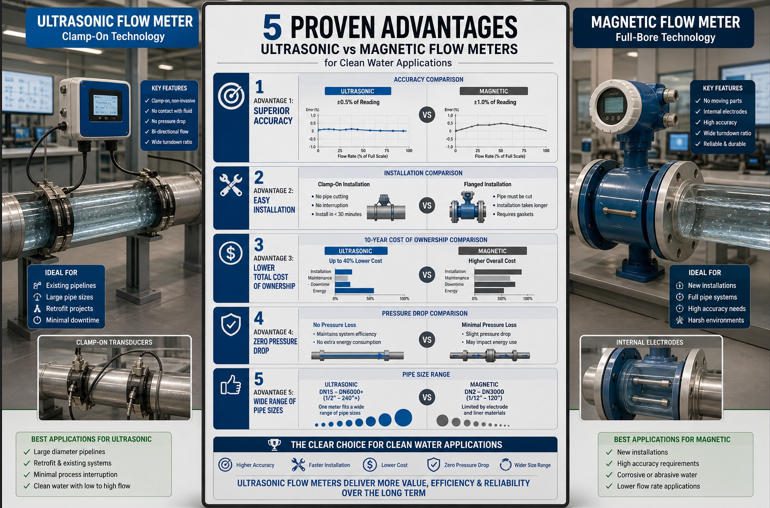
This article examines five specific advantages that ultrasonic meters hold over magnetic meters in typical clean water pipeline applications. These are engineering differences rooted in physics, validated by field data, and quantified in maintenance records, accuracy specifications, and total cost of ownership models. The analysis also addresses where magnetic meters remain the stronger choice — because responsible meter selection requires understanding both sides.
Basic Principles: How Each Technology Works
How Transit-Time Ultrasonic Meters Work
Transit-time ultrasonic flow meters use a pair of transducers positioned diagonally across the pipe. Each transducer alternately transmits and receives ultrasonic pulses. The downstream pulse (traveling with the flow) arrives faster than the upstream pulse (traveling against the flow). The meter calculates the time difference (Δt) between these two transit times and converts it into fluid velocity using the pipe geometry and transducer angle. Volumetric flow rate follows directly from velocity × cross-sectional area.
Critically, this measurement depends only on the speed of sound through the fluid — it requires no particular electrical property of the liquid. This is why ultrasonic meters measure treated municipal water, deionized water, purified water (WFI), chilled water with glycol, condensate, and essentially any clean liquid without restriction. Jade Ant Instruments’ comparison guide documents performance specifications across all of these fluid types.
How Electromagnetic (Magnetic) Meters Work
Electromagnetic flow meters apply Faraday’s law of induction: a conductive fluid flowing through a magnetic field generates a voltage proportional to its velocity. Two electromagnetic coils create the field across the pipe bore, and two electrodes embedded in the pipe wall detect the induced voltage. The meter converts this voltage into a flow measurement with typical accuracy of ±0.2% to ±0.5% of reading under ideal conditions.
The critical operational constraint is that the fluid must be electrically conductive — typically a minimum of 5 µS/cm for standard commercial magnetic meters. Municipal tap water (300–800 µS/cm) easily meets this threshold. However, deionized water (0.05–1.0 µS/cm), reverse-osmosis permeate (1–20 µS/cm), and pharmaceutical Water for Injection (typically <1.3 µS/cm per USP requirements) fall well below it — making standard magnetic meters unusable on these water types without expensive specialized low-conductivity variants.
Video: Electromagnetic vs Ultrasonic Flow Meter — Working Principle Comparison
▶ Video: Side-by-side comparison of electromagnetic and ultrasonic flow meter working principles, applications, and selection criteria. Duration: ~8 min.
Advantage 1 — No Wetted Electrodes: Reduced Wear and Maintenance Burden
Both technologies are classified as static meters with no rotating impellers. However, the nature of their internal components creates very different wear profiles over multi-year operational periods.
The Wetted-Component Problem in Magnetic Meters
Magnetic meters contain two categories of components that directly contact the process fluid: electrodes (typically stainless steel, Hastelloy C, titanium, or platinum) and an internal liner (PTFE, hard rubber, polyurethane, or ceramic) that protects the metal pipe body from corrosion. While these components have no moving parts, they are subject to electrochemical degradation, biofilm coating, scale deposition, and liner deterioration — particularly in water with elevated chloride content, variable pH, or residual disinfectant chemicals.
A 2024 analysis of 1,247 magnetic meter service records found that 20% of field failures were caused by electrode coating or fouling, and an additional 15% by internal liner condition issues — together accounting for more than one-third of all maintenance events (Soaring Instrument field failure analysis). Electrode grounding problems — where the impedance between electrode and earth exceeds 10 Ω — account for a further significant proportion of field call-outs, and grounding issues are notoriously difficult to diagnose remotely.
Why Clamp-On Ultrasonic Meters Eliminate These Failure Modes
Clamp-on ultrasonic meters have zero wetted components. The transducers mount on the exterior of the pipe; the ultrasonic signal passes through the pipe wall and fluid without any physical contact with the process fluid. There are no electrodes to coat, no liners to degrade, no internal surfaces to foul, and no grounding system to maintain.
Even inline ultrasonic meters, where transducers do contact the fluid, present inert stainless steel or titanium surfaces that resist the mild chemistry of clean water far more effectively than the mixed-material electrode-liner interfaces of magnetic meters.
Field Data: 7-Year UK Water Authority Comparison
A municipal water authority in the UK compared maintenance records across 180 inline ultrasonic meters and 220 magnetic meters installed in the same distribution network over a 7-year period. Results:
- Magnetic meters: 2.3 maintenance interventions per meter over 7 years (primarily electrode cleaning, zero-point verification, and grounding repair)
- Ultrasonic meters: 0.4 interventions per meter (primarily firmware updates and signal quality checks)
- At an average intervention cost of £450 (labour, travel, downtime), the difference amounted to approximately £385 per meter over 7 years — roughly £84,700 across the 220-magnetic-meter fleet
This 83% reduction in maintenance frequency is not an outlier — it reflects the fundamental physics of having no electrodes, no liner, and no grounding system in the measurement chain.
Source: UK water authority internal maintenance records (2017–2024). Average intervention cost: £450. Magnetic fleet cumulative additional cost: ~£84,700.
Advantage 2 — Universal Clean Water Compatibility: No Conductivity Requirement
“Clean water” is not a single, uniform fluid. The term encompasses a spectrum from heavily mineralized well water (800+ µS/cm) to semiconductor-grade ultrapure water (0.055 µS/cm) — a range spanning four orders of magnitude in conductivity. Magnetic meter compatibility narrows dramatically as conductivity decreases. Ultrasonic compatibility does not.
Conductivity Threshold: The Magnetic Meter’s Hard Limit
The Faraday induction principle requires the measured fluid to carry ions — the induced voltage is generated by the movement of charged particles through the magnetic field. Below approximately 5 µS/cm, the induced voltage signal becomes too weak for reliable measurement, and the meter reading degrades progressively. The Yokogawa ADMAG AXF specification sheet explicitly documents the minimum conductivity requirement of 5 µS/cm for standard accuracy. Below 20 µS/cm, accuracy warnings apply even on premium instruments.
An increasingly large share of clean water applications involve water types that fall below these thresholds — and this share is growing as water reuse, pharmaceutical manufacturing, semiconductor production, and high-efficiency building HVAC expand.
| Water Type | Typical Conductivity (µS/cm) | Magnetic Meter Compatible? | Ultrasonic Meter Compatible? |
|---|---|---|---|
| Municipal tap water | 300 – 800 | ✔ Yes | ✔ Yes |
| Softened water | 200 – 600 | ✔ Yes | ✔ Yes |
| Chilled water (glycol blend) | 50 – 500 | ✔ Usually yes | ✔ Yes |
| Condensate return | 0.5 – 50 | ⚠ Marginal — variable | ✔ Yes |
| Reverse osmosis (RO) permeate | 1 – 20 | ⚠ Below threshold (<5 µS/cm = unreliable) | ✔ Yes |
| Deionized (DI) water | 0.05 – 1.0 | ✘ No | ✔ Yes |
| Pharmaceutical Water for Injection (WFI) | 0.5 – 1.3 | ✘ No | ✔ Yes |
| Semiconductor ultrapure water (UPW) | 0.055 | ✘ No | ✔ Yes |
Sources: Conductivity data from Yokogawa AXF specifications and published water quality standards. Compatibility assessments from Jade Ant Instruments technical guide and Fuji Electric flow meter engineering documentation.
Biofouling Resistance: An Additional Compatibility Advantage
In clean water systems that carry residual organic matter — cooling water loops, raw water intakes, treated water reuse — biological growth on wetted surfaces is a persistent concern. Even a thin biofilm of 0.1–0.3 mm on a magnetic meter electrode surface can attenuate the induced voltage signal by 2–5%, causing measurement drift that is indistinguishable from a real flow change without independent verification.
Clamp-on ultrasonic meters eliminate this failure mode entirely because no meter component contacts the fluid. A pharmaceutical plant in Singapore reported that inline ultrasonic meters on its purified-water loop required zero cleaning interventions over 4 years, while magnetic meters on the same loop required quarterly electrode cleaning to maintain measurement within specification — representing 16 additional cleaning events per meter over the comparison period.

Figure 3. Measurement principle comparison: ultrasonic transit-time (left) requires no fluid conductivity; electromagnetic induction (right) requires minimum 5 µS/cm. (Image: Jade Ant Instruments)
Advantage 3 — Stable Accuracy Without Electrode Zero Drift
In laboratory conditions, magnetic meters deliver better headline accuracy (±0.2–0.5% of reading) than clamp-on ultrasonic meters (±1.0–2.0%). In real-world clean water pipelines operating across varying flow rates, temperatures, and fluid conditions, however, the comparison is substantially more nuanced.
Accuracy Specifications Side by Side
| Parameter | Ultrasonic — Inline (Transit-Time) | Ultrasonic — Clamp-On | Magnetic — Inline |
|---|---|---|---|
| Accuracy (% of reading) | ±0.5% to ±1.0% | ±1.0% to ±2.0% | ±0.2% to ±0.5% |
| Repeatability | ±0.15% to ±0.3% | ±0.2% to ±0.5% | ±0.1% to ±0.2% |
| Turndown ratio | Up to 200:1 | Up to 100:1 | Up to 1,000:1 |
| Minimum flow velocity | 0.01 m/s (inline); 0.03 m/s (clamp-on) | 0.03 m/s | 0.01 m/s (signal-limited below 0.3 m/s) |
| Conductivity dependency | None | None | Requires ≥5 µS/cm; accuracy degrades below 20 µS/cm |
| Zero-point stability | Excellent — no electrode drift | Excellent — no electrode drift | Subject to drift from electrode coating or grounding changes |
| Response to entrained air | Signal disruption (detectable via diagnostics) | Signal disruption (detectable) | Reading spike (may not be flagged as error) |
| EMI sensitivity | Low — acoustic principle, not electromagnetic | Low | Moderate — depends on grounding quality and shielding |
Sources: Jade Ant Instruments magnetic vs ultrasonic comparison; Badger Meter specification data; BJSSAE EMI impact analysis.
The Zero Drift Problem in Magnetic Meters
Magnetic meters are susceptible to zero drift — a gradual shift in the baseline reading caused by changes in electrode surface condition, liner properties, or grounding impedance. In a clean water system operating during low-demand periods (nighttime, weekends), even a 0.5% zero offset can create apparent “phantom flow” that undermines non-revenue water calculations and leak detection algorithms. The phantom flow reads as real consumption, masking genuine unaccounted-for losses.
Ultrasonic meters do not have electrodes and are immune to electrode-related zero drift. Their zero-point stability is inherent to the time-of-flight measurement principle. A study of 40 inline transit-time meters in a UK water distribution network documented average drift of less than 0.3% over 5 years without recalibration — versus magnetic meter drift of 0.8–1.5% over the same period in the same network before electrode cleaning cycles were performed.
⚠️ Important: Magnetic meter accuracy assumes stable conductivity ≥20 µS/cm, clean electrodes, and proper grounding. In real-world conditions, field accuracy may degrade to 2–5% due to electrode coating or grounding issues. Ultrasonic accuracy is independent of these factors.
Advantage 4 — Stable Performance Under Temperature and Pressure Variations
Clean water pipeline temperatures fluctuate seasonally and operationally — from near-freezing raw water intakes in winter to 60–80°C in hot water distribution loops, and potentially 2–8°C in chilled water systems. Temperature affects both meter technologies, but through different mechanisms with different operational consequences.
How Temperature Affects Ultrasonic Meters
In ultrasonic meters, temperature changes affect the speed of sound through the fluid — the measurement variable. The speed of sound in water varies approximately 2.4 m/s per °C across the 0–100°C range. This effect is well-characterized, predictable, and continuously compensated by modern transit-time meters using either an integrated temperature sensor or an external RTD/thermocouple input. The compensation is a straightforward lookup-table correction that requires no recalibration when the temperature operating range changes seasonally.
Jade Ant Instruments’ ultrasonic flow meters support three-channel 4–20 mA analog input for external temperature and pressure transmitters, enabling simultaneous real-time compensation and allowing direct energy metering (BTU calculation) when paired with temperature sensors on supply and return lines.
How Temperature Affects Magnetic Meters — and Where the Risk Lies
Temperature changes affect magnetic meters through two mechanisms. First, fluid conductivity changes approximately 2% per °C for most aqueous solutions — this does not directly affect measurement in high-conductivity tap water, but becomes significant when operating near the minimum conductivity threshold. Second, differential thermal expansion between the liner (especially PTFE) and the metal pipe body creates dimensional stress at the liner-to-pipe interface, potentially causing liner lifting, gaps, and accuracy degradation.
The conductivity-temperature interaction creates a hidden risk in transitional applications: an RO permeate system with baseline conductivity of 8 µS/cm at 25°C can drop below 5 µS/cm during a winter cold snap, pushing the magnetic meter below its reliable operating threshold without any diagnostic alarm being triggered. Ultrasonic meters have no conductivity threshold and are not subject to this failure mode.
| Parameter | Ultrasonic — Clamp-On | Ultrasonic — Inline | Magnetic — Inline (PTFE liner) |
|---|---|---|---|
| Fluid temperature range | −20°C to +150°C (transducer-dependent) | −40°C to +200°C | −20°C to +180°C (PTFE); −20°C to +80°C (hard rubber) |
| Maximum pressure | Limited by pipe rating (up to 40+ bar) | Up to 40 bar (PN40) | Up to 40 bar (PN40) |
| Temperature effect on measurement | Speed-of-sound correction — compensated by firmware | Same as clamp-on; better compensation with external sensor | Conductivity shift (critical near 5 µS/cm); PTFE liner expansion |
| IP protection rating | IP67 / IP68 (sensor) | IP67 / IP68 | IP67 / IP68 |
| ATEX / IECEx available | ✔ Yes | ✔ Yes | ✔ Yes |
Advantage 5 — Installation Flexibility: Clamp-On Non-Invasive Measurement
This is the single most operationally impactful advantage of ultrasonic technology over magnetic technology for retrofit clean water applications. Ultrasonic meters are available in clamp-on, insertion, and inline configurations. Magnetic meters are only available as inline devices requiring pipe cutting and process shutdown.
Clamp-On vs Inline: The Installation Reality
A clamp-on ultrasonic meter installs in three steps: (1) enter pipe parameters into the transmitter, (2) apply acoustic couplant to the transducer faces, (3) mount the transducers at the calculated spacing on the pipe exterior. Total time for a trained technician on a DN100 pipe: 30–60 minutes. The pipeline remains in full operation throughout. There is zero contamination risk, zero shutdown cost, and zero pipe modification cost. If the initial installation position produces poor signal quality due to upstream disturbances, the transducers can be repositioned in 5 minutes with no material cost.
A magnetic meter installation requires: cutting the pipeline (shutdown mandatory), preparing the pipe ends, installing flanges or wafer clamps, inserting the meter body and torquing fasteners, running earth bonds to ensure grounding impedance below 10 Ω, connecting the power and signal cables, and running a zero-point calibration with the pipe full of static fluid. Total time for a two-person crew with a welder and electrician on a DN100 pipe: 4–8 hours minimum.
| Installation Factor | Ultrasonic — Clamp-On | Ultrasonic — Inline | Magnetic — Inline |
|---|---|---|---|
| Pipe cutting required | No | Yes | Yes |
| Process shutdown required | No | Yes | Yes |
| Typical installation time (DN100) | 30–60 minutes | 4–6 hours | 4–8 hours |
| Crew requirement | 1 technician | 2 technicians + welder | 2 technicians + welder + electrician |
| Grounding rings required | No | No | Yes (mandatory on non-metallic pipe) |
| Contamination risk | Zero | Minimal (controlled) | Minimal (controlled) |
| Relocatable after installation | Yes — fully portable | No | No |
| Suitable for temporary measurement | Ideal | No | No |
| Upstream straight-run required | 10–20D (single path); 5D (multi-path) | 10D (single); 5D (multi-path) | 5D upstream / 3D downstream |
| Compatible pipe materials | Steel, stainless, copper, PVC, HDPE, cast iron, concrete | Meter body material dependent | Non-magnetic section required; compatible with most metals and PVC |

Non-Revenue Water Monitoring: Why Clamp-On Wins for DMA Surveys
District Metered Area (DMA) surveys for non-revenue water detection require flow measurement at dozens or hundreds of locations across a distribution network — often on live, pressurized mains that cannot be shut down, and at locations that may be temporary or may change as the network topology evolves. Clamp-on ultrasonic meters are the only technology that satisfies all of these constraints simultaneously. A UK utility that deployed continuous clamp-on ultrasonic monitoring across its DMA boundary points achieved a 12% reduction in non-revenue water within 18 months — translating to recovered revenue that paid back the meter investment in under 9 months.
Jade Ant Instruments offers clamp-on ultrasonic meters covering DN32–DN1000 mm with IP68-rated sensors and optional data logging, making them directly applicable to DMA monitoring programs without requiring permanent pipe modifications.
Handling Real-World Temperature and Pressure Variations: Field Considerations
Seasonal Temperature Swings in Municipal Water Networks
Municipal water mains in temperate climates experience fluid temperature swings of 8–20°C between summer and winter. In northern Europe and northern North America, near-freezing water at 1–4°C in winter is followed by 18–22°C summer supply temperatures. Ultrasonic meter firmware continuously adjusts for the speed-of-sound change across this range, maintaining consistent accuracy without intervention. Magnetic meter accuracy is unaffected by temperature per se, but conductivity does shift — and in low-conductivity applications (RO permeate, softened water), this shift can cross the measurement threshold.
Pressure Transients and Water Hammer
Pressure transients from pump starts, valve closures, and water hammer events affect both technologies, but in different ways. Ultrasonic meters can detect pressure waves as momentary changes in transit time — appearing as brief flow spikes in the data record. Well-designed meters apply digital damping (configurable 0.5–60 second response time) to filter these transients from the trend record while preserving real flow data. Magnetic meters are largely immune to pressure transients in the direct measurement channel, but cavitation caused by severe pressure drops (below fluid vapor pressure) introduces vapor bubbles that disrupt the induced voltage signal and generate erratic readings — often without a diagnostic alarm.
Installation Best Practices for Clamp-On Ultrasonic Meters in Clean Water Pipelines
Step-by-Step Installation Protocol
The following procedure applies to transit-time clamp-on ultrasonic meters on clean water pipelines (DN50–DN600):
- Identify a straight pipe section: Measure a minimum of 10D upstream from the nearest elbow, valve, pump, or reducer, and 5D downstream from the nearest disturbance. Mark the installation location.
- Verify pipe condition: Check for heavy external corrosion, scale deposits, or thick internal linings (rubber >6 mm, concrete) that may attenuate the ultrasonic signal. Use an ultrasonic thickness gauge to verify wall thickness matches pipe schedule data.
- Enter pipe parameters: Input outer diameter, wall thickness, pipe material, and liner details into the transmitter. The meter calculates the optimal transducer spacing (W or V mode) automatically.
- Apply acoustic couplant: Use the manufacturer-recommended couplant (typically silicone grease for temperatures up to 80°C; high-temperature paste above 80°C). Apply a 2–3 mm layer to the transducer face.
- Mount transducers: Position transducers at the calculated spacing, confirm signal strength indicator is in the green zone (>70% signal quality), and tighten the rail clamps.
- Verify zero flow reading: If possible, close an isolation valve downstream and verify the meter reads zero. Any non-zero reading at confirmed zero flow indicates grounding noise, air entrainment, or installation error — diagnose before recording data.
- Commission output signals: Configure 4–20 mA span, pulse output (if required for totalization), and Modbus register mapping. Log flow data for a minimum 24-hour period to confirm stable readings across the demand cycle.
Maintenance and Lifecycle Planning: Ultrasonic vs Magnetic
Calibration Frequency and Drift Management
Both technologies benefit from periodic calibration verification. The frequencies differ significantly due to the differing drift mechanisms:
- Magnetic meter: Zero-point verification every 6–12 months; electrode condition inspection every 6–24 months (shorter in biofouling-prone systems); full traceable calibration every 2–3 years. Reference: Fluke Calibration Best Practices.
- Inline ultrasonic meter: Signal quality verification every 12 months; transducer face inspection every 2–3 years; full calibration verification every 3–5 years.
- Clamp-on ultrasonic meter: Annual signal quality check (10 minutes); couplant condition inspection every 1–2 years; battery replacement every 3–5 years (battery-powered models). No factory calibration required in most clean water monitoring applications.
Spare Parts and Lifecycle Cost Drivers
Magnetic meter spare-parts requirements include replacement electrodes, liner repair kits, transmitter boards, and grounding rings. Inline ultrasonic meter spare parts are limited to replacement transducers (typical lifespan: 10–15 years) and transmitter electronics. Clamp-on meters require transducer replacement (rare — typical lifespan exceeds 15 years) and periodic renewal of coupling compound or pads at approximately $15–$30 per service event.
Both technologies carry a 15–25 year design life in clean water service. Magnetic meters can reach the upper end when liner and electrode materials are correctly matched to the water chemistry. Ultrasonic meters — particularly clamp-on configurations — have fewer degradation pathways and maintain their performance specifications more predictably throughout the lifecycle because there are no wetted components subject to chemical or biological attack.
Cost and Total Cost of Ownership (TCO) — 10-Year Analysis
Capital Expenditure vs Operating Expenditure
The headline purchase price comparison between ultrasonic and magnetic meters narrows significantly when installation, downtime, calibration, and maintenance are included in a 10-year TCO model. The table below presents representative 2025–2026 pricing for DN100 clean water applications.
| Cost Category | Ultrasonic — Clamp-On | Ultrasonic — Inline | Magnetic — Inline |
|---|---|---|---|
| Meter purchase price | $1,500 – $4,000 | $2,500 – $6,000 | $2,000 – $5,000 |
| Installation labour + materials | $200 – $500 | $1,500 – $3,000 | $1,800 – $3,500 |
| Process downtime cost | $0 | $500 – $5,000 | $500 – $5,000 |
| Calibration (3 events over 10 yr) | $0 – $900 | $1,500 – $2,700 | $2,400 – $3,600 |
| Maintenance (10-yr cumulative) | $300 – $600 | $500 – $1,000 | $1,200 – $2,500 |
| Grounding and bonding components | $0 | $0 | $100 – $400 |
| 10-Year TCO Range | $2,000 – $6,000 | $6,500 – $13,700 | $8,000 – $20,000 |
Pricing data compiled from distributor quotations, manufacturer list prices, and TCO methodology from RS Hydro / Flowmeters.co.uk TCO analysis. Downtime cost varies by application — hospital water shutdown: $5,000–$15,000 per event; commercial building: $200–$500. Jade Ant Instruments offers factory-direct pricing for both ultrasonic and electromagnetic meters.
~$4,000
10-yr TCO
Clamp-On Ultrasonic
~$14,000
10-yr TCO
Magnetic Inline
Meter Purchase Price
Installation + Downtime Cost
Calibration (3 events, 10 yr)
Maintenance + Grounding
For clamp-on ultrasonic: installation and downtime cost is near-zero. For magnetic inline: installation and downtime often represents the largest single cost category — especially in shutdown-sensitive facilities.
Selection Recommendations: When to Choose Ultrasonic, When to Choose Magnetic
Choose Ultrasonic Flow Meters When:
- The water conductivity is below 20 µS/cm at any point during the year (RO permeate, condensate return, softened water approaching seasonal lows)
- The fluid is DI water, WFI, or semiconductor ultrapure water (conductivity <5 µS/cm) — magnetic meters simply cannot function reliably
- The pipeline cannot be shut down or modified for installation (retrofit, live mains, continuous pharmaceutical processes)
- The measurement is temporary or the meter must be relocated between monitoring points (DMA surveys, energy audits, system balancing)
- The pipe diameter exceeds DN500 — large-bore magnetic meters are extremely expensive and heavy; clamp-on ultrasonic scales with no cost penalty for pipe size
- Grounding is unreliable or the pipe is plastic/lined material where grounding ring installation is complex
- The 10-year lifecycle budget favors lowest total installed cost over highest laboratory accuracy
- The installation is in a facility where water system shutdown carries significant indirect costs (hospitals, data centers, food production)
Choose Magnetic Flow Meters When:
- The water conductivity is reliably above 20 µS/cm throughout the year (most municipal tap water, process water with ionic content)
- The application demands ±0.2% fiscal-grade accuracy for custody transfer or billing — magnetic meters achieve this more cost-effectively than single-path ultrasonic
- Very low flow velocities are expected (<0.03 m/s) where the magnetic meter’s wider turndown ratio (up to 1,000:1) provides better resolution than clamp-on ultrasonic
- The installation is in new construction where pipe cutting is planned from the outset and the total installed cost difference is minimal
- Highly abrasive or particle-laden liquids are present (though this scenario falls outside “clean water” by definition)
| Application Scenario | Recommended Technology | Key Deciding Factor |
|---|---|---|
| Pharmaceutical purified water / WFI loop | Ultrasonic (Inline) | Conductivity <1.3 µS/cm — magnetic meter not viable |
| HVAC chilled water retrofit | Ultrasonic (Clamp-On) | No shutdown possible; 1–2% accuracy adequate |
| Municipal DMA flow monitoring | Ultrasonic (Clamp-On) | Temporary/relocatable; live main; no pipe cutting |
| Semiconductor UPW loop | Ultrasonic (Inline) | Conductivity 0.055 µS/cm — magnetic not viable; no contamination risk |
| Municipal fiscal water metering (DN150) | Magnetic (Inline) | ±0.2–0.5% accuracy for billing; conductivity reliable >300 µS/cm |
| RO permeate pipeline | Ultrasonic (Inline) | Conductivity variable 1–20 µS/cm — below magnetic threshold |
| Building water sub-metering (DN50–DN100) | Ultrasonic (Clamp-On) | Multiple points; non-invasive; budget-constrained; audit accuracy sufficient |
| Condensate return (steam system) | Ultrasonic (Inline or Clamp-On) | Variable conductivity (0.5–50 µS/cm); temperature swings; mag meter risky |
| Raw water intake (pre-treatment) | Either — evaluate conductivity | If conductivity >20 µS/cm consistently: magnetic. Variable/low: ultrasonic. |
For engineering support on ultrasonic meter sizing, pipe compatibility assessment, and installation planning, the Jade Ant Instruments 5-factor selection framework provides a structured decision methodology that addresses fluid properties, pipe conditions, accuracy requirements, and lifecycle economics. Their electromagnetic flow meter selection guide similarly provides detailed liner and electrode specification support for magnetic meter applications where that technology is the correct choice.
The 5 Advantages Summarized
Across typical clean water pipeline applications in 2025–2026, transit-time ultrasonic flow meters deliver five engineering advantages over electromagnetic magnetic meters that translate directly into lower lifecycle costs, broader fluid compatibility, more reliable long-term accuracy, and significantly simpler retrofit installation.
- Reduced maintenance burden: 83% fewer field interventions over 7 years — no electrodes, no liners, no grounding systems to maintain.
- Universal clean water compatibility: Transit-time measurement is independent of conductivity — the only standard technology for DI water, WFI, ultrapure water, and low-conductivity fluids where magnetic meters cannot function.
- Stable, drift-free accuracy: No electrode-related zero drift means more reliable minimum night flow data, more trustworthy leak detection, and longer calibration intervals.
- Temperature and pressure resilience: Predictable, continuously compensated response to temperature changes — no conductivity-threshold risk at seasonal temperature extremes.
- Unmatched installation flexibility: Clamp-on configuration enables zero-downtime installation in 30–60 minutes, portability across measurement points, and retrofit capability that saves $2,000–$15,000 per installation point in shutdown-sensitive facilities.
The ultrasonic option offers tangible, quantified benefits in maintenance, water compatibility, accuracy stability, environmental resilience, and installation flexibility — making it the stronger choice in a wide range of clean water pipeline scenarios. However, magnetic meters retain advantages where ±0.2% fiscal-grade accuracy is required, where very low flow velocities demand wide turndown, and where conductivity is reliably high and grounding is engineered properly from installation. Select the technology that matches your actual pipeline conditions — not a general preference.
Jade Ant Instruments manufactures both ultrasonic and electromagnetic flow meters to ISO quality standards, supplying to municipal water utilities, pharmaceutical facilities, HVAC contractors, and industrial process plants across more than ten sectors. Their engineering team provides free technical consultation on meter selection, sizing, and installation planning.
Frequently Asked Questions (FAQs) — Ultrasonic vs Magnetic Flow Meters for Clean Water
Q1. What are the five main advantages of ultrasonic over magnetic flow meters for clean water pipelines?
Q2. Can ultrasonic flow meters be installed on existing clean water pipelines without shutting down the system?
Q3. What is the minimum conductivity required for a magnetic flow meter to function reliably?
Q4. How accurate are clamp-on ultrasonic flow meters compared to magnetic flow meters?
Q5. What is the expected maintenance schedule for clamp-on ultrasonic meters in a municipal water application?
Q6. Do ultrasonic flow meters work on all pipe materials used in water distribution networks?
Q7. How does the 10-year total cost of ownership compare between clamp-on ultrasonic and magnetic flow meters for a DN100 clean water application?
Q8. Can ultrasonic flow meters reduce non-revenue water (NRW) losses in municipal water distribution?
Q9. What communication protocols do modern ultrasonic flow meters support for SCADA and BMS integration?
Q10. When should I choose a magnetic flow meter over an ultrasonic meter for clean water service?
References and Further Reading
- Jade Ant Instruments — 5 Advantages of Ultrasonic vs Magnetic Meters for Water
- Jade Ant Instruments — Magnetic vs Ultrasonic Flow Meters: Performance and Cost Comparison
- Jade Ant Instruments — Electromagnetic Flow Meter Selection Guide: Liner, Electrode and Sizing
- Jade Ant Instruments — How to Choose a Flow Meter: 5 Factors (2026)
- Yokogawa — ADMAG AXF Magnetic Flow Meter Specifications
- Badger Meter — Ultrasonic Clamp-On vs Electromagnetic Insertion: 4 Reasons Users Prefer Clamp-On
- BJSSAE — The Impact of EMI on Flow Meter Accuracy and Precision
- Soaring Instrument — Critical Straight-Run Requirements for Different Flow Meters
- McCrometer — Using Flow Meters to Reduce Non-Revenue Water
- RS Hydro / Flowmeters.co.uk — Why Total Cost of Ownership Matters More Than Purchase Price
- Fluke — Flow Meter Calibration: Five Best Practices
- Fuji Electric — Ultrasonic Flow Meter Advantages and Disadvantages vs Mag Meter
- Kamstrup — Ultrasonic Meters vs Electromagnetic Meters
- MarketsandMarkets — Flow Meter Market Report 2024–2029
- Mordor Intelligence — Ultrasonic Flow Meters Market 2026–2031