Differential pressure flow meters are widely used in oil and gas, chemical plants, steam systems, water treatment, HVAC, and utility networks. They are popular because the core idea is simple: create a pressure drop, measure it, and convert that pressure difference into flow.
This tutorial explains how differential pressure flow meters work, what parts they use, how flow is calculated, how to install and maintain them, and how to run a practical measurement workflow in the field.
The article is written for engineers, technicians, operators, and buyers who need a clear working explanation without unnecessary jargon. Technical terms are defined when they first appear.

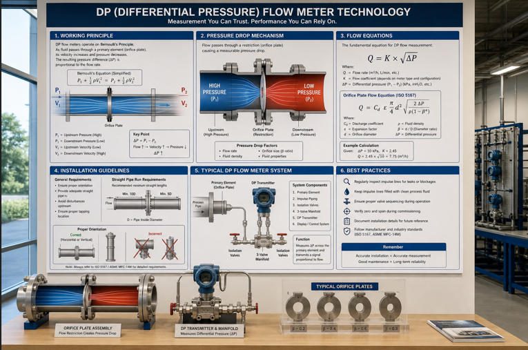
A differential pressure flow meter, often called a DP flow meter, measures flow by using pressure difference. The meter includes a primary flow element, such as an orifice plate, Venturi tube, or flow nozzle. This element changes the flow path and creates a pressure drop.
A transmitter then measures the difference between upstream pressure and downstream pressure. The control system or flow computer converts that pressure difference into flow rate.
This article covers:
- Basic DP flow meter principles
- Common flow elements and pressure taps
- Flow calculation and simplified equations
- Orifice, Venturi, nozzle, and averaging pitot options
- Selection criteria for different applications
- Calibration and uncertainty checks
- Installation and maintenance best practices
- A step-by-step practical measurement workflow
Expected takeaway: by the end, you should understand why tap placement, straight pipe, fluid density, transmitter range, and maintenance condition can matter as much as the meter type itself.
Quick Glossary Before We Start
- DP: Differential pressure. It means the pressure difference between two points.
- Pressure tap: A small connection point on the pipe used to sense pressure.
- Primary element: The part installed in the pipe to create a pressure drop, such as an orifice plate.
- Transmitter: The instrument that converts pressure difference into an electrical signal.
- Flow coefficient: A correction factor used to make a real-world flow calculation more accurate.
For broader meter selection, Jade Ant Instruments provides a practical flow meter selection guide that compares meter types by fluid, installation, pressure loss, and lifecycle cost.
Fundamentals of Differential Pressure Flow Meters
Core Principle: DP Equals Upstream Minus Downstream Pressure
The core idea is simple:
Differential pressure = upstream pressure − downstream pressure
When fluid passes through a restriction, it speeds up. As velocity increases, static pressure drops. The DP transmitter measures this pressure drop.
Flow is then estimated from the pressure difference. In simple terms:
Higher flow creates higher differential pressure.
However, the relationship is not straight-line. Flow is roughly proportional to the square root of DP:
Flow ∝ √DP
This matters in low-flow conditions. If the DP signal becomes very small, measurement noise and zero drift can create larger flow errors.
Common Elements: Sensing Elements, Pressure Taps, and Orifice Plates
A typical DP flow system contains four basic parts:
- Primary element: Creates the pressure drop. Examples include orifice plates, Venturi tubes, flow nozzles, and averaging pitot tubes.
- Pressure taps: Small ports that pick up upstream and downstream pressure.
- Impulse lines: Tubing that carries pressure from the taps to the transmitter.
- DP transmitter: Measures the difference and sends a signal, usually 4–20 mA, HART, Modbus, or another industrial output.
Basic DP Flow Meter Layout
Flow direction
Primary element
High-pressure tap
Low-pressure tap
DP Transmitter
PLC / DCS
The transmitter measures pressure difference. The control system converts that DP value into flow.
Basic Units, Symbols, and Typical Measurement Ranges
DP flow measurement uses several common units. The pressure unit depends on the plant standard, country, and instrument range.
| Item | Common Symbol | Common Units | Plain-English Meaning |
|---|---|---|---|
| Differential pressure | ΔP | Pa, kPa, mbar, inH₂O, psi | The pressure drop measured across the flow element |
| Flow rate | Q | m³/h, L/min, GPM, kg/h | How much fluid passes through the pipe per time |
| Density | ρ | kg/m³, lb/ft³ | How heavy the fluid is for its volume |
| Discharge coefficient | Cd | Dimensionless | A correction factor for real flow behavior |
| Beta ratio | β | Dimensionless | Orifice bore diameter divided by pipe internal diameter |
For industrial DP systems, pressure ranges may be very small for airflow or very high for steam and gas service. Correct transmitter range selection is important. A transmitter ranged too widely may not read low flow well.
How Differential Pressure Is Generated in Flow Elements
Orifice Plates: Theory and Pressure Drop
An orifice plate is a thin plate with a carefully machined hole. It is installed between flanges. As fluid passes through the hole, velocity increases and pressure drops.
Orifice plates are common because they are simple, standardized, and cost-effective. They are often used in steam, gas, water, and process liquids.
The trade-off is pressure loss. An orifice plate can create a permanent pressure loss that increases pump or compressor energy use.

Jade Ant Instruments explains related selection trade-offs in its article on small-line differential pressure flow meters, where pressure loss and installation space become especially important.
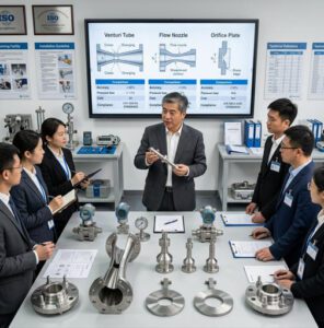
Venturi and Flow Nozzle: Advantages and Differences
A Venturi tube narrows smoothly and then expands smoothly. This shape creates DP with lower permanent pressure loss than an orifice plate.
A flow nozzle is stronger than a sharp-edged orifice and works well in high-velocity service, especially steam. It usually has more pressure loss than a Venturi but can be more durable than an orifice plate in harsh service.
| Flow Element | Main Strength | Main Limitation | Typical Use |
|---|---|---|---|
| Orifice plate | Low cost, standardized, easy to replace | Higher permanent pressure loss | Steam, water, gas, general process lines |
| Venturi tube | Lower pressure loss and good recovery | Higher purchase cost and larger body | Large water lines, low-loss applications |
| Flow nozzle | Good for high velocity and steam | Less pressure recovery than Venturi | Boiler feedwater, steam, high-speed flow |

For flow nozzle applications, see Jade Ant Instruments’ guide to flow nozzle meter advantages and disadvantages.
Tap Locations, Upstream/Downstream Considerations, and Effects of Installation
Pressure taps must be located correctly. If the taps are too close, too far, blocked, leaking, or installed in a disturbed flow area, the DP signal can be wrong.
Upstream fittings also matter. Elbows, valves, pumps, reducers, and tees can distort the flow profile. This means the velocity is not evenly distributed across the pipe.
For DP meters, this can change the pressure drop and the final flow reading.
For standards-based installation guidance, ISO 5167 differential pressure flow measurement is one of the key references for orifice plates, nozzles, Venturi tubes, and cone meters.
The DP–Flow Relationship and Governing Equations
Continuity and Energy Balance Overview
Two basic ideas explain DP flow measurement.
Continuity means the same amount of fluid must pass through each section of a full pipe. When the pipe area becomes smaller, the fluid velocity increases.
Energy balance means pressure energy and velocity energy are linked. When velocity increases through a restriction, static pressure falls.
This is why a restriction creates a measurable pressure drop.
Discharge Coefficients and Their Dependence on Reynolds Number
The discharge coefficient, or Cd, corrects the ideal flow equation for real-world behavior.
Real flow is affected by friction, turbulence, edge shape, pipe roughness, and fluid properties. Cd helps account for those effects.
Reynolds number is a dimensionless value that indicates whether flow is smooth, transitional, or turbulent. In simple terms, it compares flow momentum with fluid viscosity.
Example:
- Thick syrup at low speed may have low Reynolds number.
- Water or steam at higher speed usually has high Reynolds number.
Many DP standards and vendor calculations use Reynolds number to refine the discharge coefficient.
Practical Flow Equations for DP Meters: Simplified View and When to Consult Calibration Data
A simplified liquid flow relationship is:
Q = K × √ΔP
Where:
- Q = flow rate
- K = meter factor based on geometry, fluid density, and coefficients
- ΔP = differential pressure
This simplified equation is useful for understanding the concept. For real industrial work, use the manufacturer’s sizing sheet, ISO/API calculation, or calibration data.
For gas and steam, do not rely only on a simple equation. Pressure, temperature, density, and compressibility may need compensation.
DP Rises Faster Than Flow
Example: if flow doubles, DP becomes about four times higher
0
25
50
75
100
125
25%
50%
75%
100%
Flow rate as % of maximum
DP as % of maximum
Common Types of Differential Pressure Meters
Orifice Plate Meters: Characteristics and Typical Use Cases
Orifice plate meters are the most familiar DP meters. They are simple, standardized, and relatively inexpensive.
They are often used for:
- Steam flow
- Compressed air
- Natural gas
- Cooling water
- Process liquids
The main downside is permanent pressure loss. In continuous operation, this can become an energy cost.
Venturi Meters: Advantages, Limitations, and Efficiency Considerations
Venturi meters are useful when pressure loss must be low. They are common in large water lines and applications where pumping energy matters.
The main limitation is size and cost. A Venturi meter usually costs more than an orifice plate and needs more space.
Other DP Meters: Flow Nozzles, Averaging Meters, Multipoint Taps; When They’re Used
Other DP devices include flow nozzles, averaging pitot tubes, cone meters, wedge meters, and multipoint averaging devices.
Each solves a different field problem:
- Flow nozzle: Good for high-velocity steam and high-temperature service.
- Averaging pitot tube: Useful in larger ducts and pipes with moderate pressure loss.
- Cone meter: Can work better in shorter straight-run conditions than some traditional DP elements.
- Wedge meter: Often used for dirty, viscous, or slurry-like fluids.
For a wider industrial comparison, see Jade Ant Instruments’ article on industrial flow monitor technologies.
How to Select a DP Meter for an Application
Fluids, Viscosities, and Compressibility Considerations
Start with the fluid. Is it liquid, gas, or steam? Is it clean, dirty, corrosive, viscous, or two-phase?
Compressibility means the fluid density changes when pressure changes. Gases and steam are compressible. Most liquids are much less compressible.
For gas and steam, density compensation is often required. This usually means adding pressure and temperature inputs.
Rangeability, Accuracy Targets, and Installation Context
Rangeability means the meter can measure both high and low flows within useful accuracy. DP meters can struggle at very low flows because the DP signal becomes small.
Before selecting a DP meter, define:
- Minimum flow
- Normal flow
- Maximum flow
- Required accuracy
- Available straight pipe
- Allowed pressure loss
- Maintenance access
Maintenance, Calibration, and Compatibility with Existing Systems
Check whether the meter can be maintained without long shutdowns. Also check whether the output signal matches the plant control system.
Common outputs include 4–20 mA, pulse, HART, Modbus, Profibus, and Foundation Fieldbus.
Jade Ant Instruments often sees better project outcomes when engineers review maintenance access before purchasing. A low-cost primary element can become expensive if removal requires full line isolation, scaffolding, permits, and extended shutdown time.
| Selection Factor | Question to Ask | Why It Matters | Example Risk If Ignored |
|---|---|---|---|
| Fluid phase | Liquid, gas, steam, or mixed phase? | Density and compressibility affect calculation | Wet steam can cause over-reading or unstable readings |
| Flow range | What are min, normal, and max flow? | DP signal is weak at low flow | Meter reads poorly during low-load operation |
| Pressure loss | How much permanent loss is acceptable? | Pressure loss becomes energy cost | Pump or compressor power increases |
| Straight run | Is enough pipe length available? | Disturbed flow changes DP | Elbows or valves create biased measurement |
| Maintenance | Can taps and impulse lines be inspected? | Plugging and leaks are common faults | Technicians recalibrate repeatedly but do not fix root cause |
Calibration, Accuracy, and Uncertainty Considerations
Factory Calibration Versus Field Calibration
Factory calibration is performed before the instrument is shipped. It confirms the transmitter or complete meter under controlled conditions.
Field calibration checks the installed system. This is important because real installations include impulse lines, valves, taps, process temperature, vibration, and actual fluid behavior.
A transmitter can pass bench calibration and still read incorrectly in the field if the pressure taps are blocked or the orifice plate is damaged.
Influence of Reynolds Number and Pipe Conditions
Pipe condition affects accuracy. Rust, scale, deposits, rough internal surfaces, or incorrect pipe diameter can change the flow profile and meter factor.
Reynolds number also matters because it changes how the fluid behaves around the restriction. This affects discharge coefficient and uncertainty.
Methods to Evaluate and Quantify Measurement Uncertainty
Measurement uncertainty is the expected range of doubt around a measurement result. It is not the same as an error. It is a structured way to say, “How much can we trust this number?”
Common uncertainty sources include:
- Transmitter accuracy
- Primary element geometry
- Fluid density data
- Pipe internal diameter
- Pressure tap condition
- Temperature measurement
- Flow profile and straight-run condition
For calibration planning, Fluke’s flowmeter calibration best practices provide useful guidance on traceability and matching calibration conditions to field conditions.
Typical DP Flow Uncertainty Sources
Qualitative example for field review, not a universal rule
Uncertainty
Sources
Transmitter & electronics: 20%
Primary element geometry: 25%
Fluid density data: 15%
Installation effects: 25%
Maintenance condition: 15%
Installation Best Practices for Reliable Measurements
Straight-Run Requirements and Pipe Fittings
DP meters need stable flow. Straight pipe before and after the primary element helps the flow profile become more predictable.
Valves, elbows, reducers, pumps, and tees placed too close to the meter can create swirl or uneven velocity. This changes the pressure drop and can bias the reading.
Always follow the meter supplier’s installation drawing and relevant standards. Do not assume one straight-run rule fits every primary element.
Pressure Tap Placement, Tapping Diameter, and Potential Leaks
Pressure taps should be clean, correctly sized, and placed according to the meter design.
Impulse lines should be short, properly sloped, and protected from freezing or plugging. For steam, condensate pots and equal liquid columns may be needed.
Small leaks matter. A leak on the high-pressure side or low-pressure side changes the DP signal.
Bypass, Surge, and Thermal Effects to Monitor
A three-valve or five-valve manifold can help isolate and zero the transmitter safely. Bypass valves must be used correctly; an incorrectly opened equalizing valve can make the DP signal collapse.
Surge and water hammer can damage transmitters and primary elements. Thermal expansion can also stress impulse lines and fittings.

Maintenance, Diagnostics, and Troubleshooting
Common Failure Modes: Drift, Blockages, Fouling
Common DP flow meter problems include:
- Zero drift: The transmitter output shifts when no DP should exist.
- Plugged impulse line: The pressure signal cannot reach the transmitter correctly.
- Fouled orifice plate: Deposits change the effective bore and edge condition.
- Leaking manifold valve: High and low sides can partly equalize.
- Wet gas or two-phase flow: Liquid in gas service can create unstable DP.
Routine Checks and Preventive Maintenance
A practical maintenance plan should include:
- Check zero under safe equalized conditions
- Inspect impulse lines for plugging, corrosion, or leaks
- Confirm manifold valve positions
- Inspect orifice plate edge condition during shutdown
- Verify density, pressure, and temperature settings in the control system
- Compare current readings with historical operating patterns
Jade Ant Instruments recommends recording “as-found” and “as-left” data. This helps reliability teams see whether a loop is stable or slowly degrading.
Step-by-Step Troubleshooting Flowchart
DP Flow Meter Troubleshooting Flowchart
Reading abnormal?
Check process condition
Flow, pressure, temperature stable?
Check manifold valves
Equalize, isolate, and block valves correct?
Inspect impulse lines
Plugging, leaks, freezing, condensate?
Verify transmitter
Zero, span, damping, square-root setting?
Confirm with cross-check or calibration
If still wrong:
Inspect primary element,
tap condition, and DCS
Applications, Standards, and Industry Context
Typical Industries and Use Cases: Oil & Gas, Chemical, Water Treatment
DP flow meters are used across many industries because they can handle liquids, gases, and steam when correctly designed.
- Oil and gas: Gas flow, steam, produced water, injection systems, and process balancing.
- Chemical plants: Process liquids, solvents, acids, steam, and utility lines.
- Water treatment: Raw water, treated water, sludge-related lines, and plant utilities.
- Power and utilities: Steam, boiler feedwater, condensate, and compressed air.
- HVAC: Chilled water, heating water, and air systems.
Relevant Standards and Guidelines: ISO, API, AGA/ISA Where Applicable
Several standards and guidelines may apply depending on the industry and meter type.
- ISO 5167: Covers many DP devices such as orifice plates, nozzles, Venturi tubes, and cone meters.
- API guidance: Often used in oil, gas, and refinery applications.
- AGA reports: Commonly used for gas measurement applications.
- ISA resources: Useful for instrumentation practices, control loops, and signal integration.
For general DP flow principles and pressure loss discussion, the Engineering ToolBox guide to orifice, nozzle, and Venturi meters is a practical reference.
How Standards Influence Installation and Calibration Procedures
Standards influence the meter geometry, tap locations, straight-run needs, calculation method, and documentation.
They also help engineers avoid guesswork. For example, an orifice plate calculation should not be based only on bore size. It should also consider pipe internal diameter, beta ratio, Reynolds number, tap type, fluid density, and installation condition.
Practical Step-by-Step Measurement Workflow
Pre-Checks and System Readiness
Before taking a DP flow measurement, confirm the system is ready.
- Confirm the correct meter tag number.
- Check that the pipe is full for liquid service.
- Confirm flow direction.
- Verify that isolation and manifold valves are in the correct position.
- Check impulse lines for leaks or blockage signs.
- Confirm transmitter range and output type.
- Confirm fluid density, pressure, and temperature values used by the calculation.
Performing a Measurement: Setup, Taps, and Data Collection
During measurement, collect more than one number. A reliable field check should include process context.
Record:
- Differential pressure
- Line pressure
- Temperature
- Flow output from transmitter or DCS
- Valve positions
- Process condition, such as startup, normal load, or shutdown
- Any alarms or diagnostic messages
Interpreting Results and Validating with Cross-Checks
Do not trust one reading without context. Compare the DP flow result with other available data.
Useful cross-checks include:
- Pump curve or compressor curve
- Tank level change over time
- Batch weight or mass balance
- Heat balance for steam systems
- Temporary clamp-on ultrasonic meter, where suitable
- Historical trend at similar operating conditions
For broader instrumentation selection and validation, Jade Ant Instruments’ flowmeter sensor selection factors article provides useful checks on accuracy, installation, output signals, and lifecycle cost.
Recommended YouTube Video
The video below gives a visual explanation of DP flow meter types, including orifice, Venturi, and nozzle sensor elements.
Differential pressure flow meters measure flow by creating and measuring pressure drop. The principle is simple, but reliable field measurement depends on many details.
The key takeaways are:
- DP flow equals pressure difference converted into flow by a square-root relationship.
- Orifice plates, Venturi tubes, flow nozzles, and averaging devices each have different trade-offs.
- Tap placement, impulse-line condition, and straight pipe can strongly affect accuracy.
- Calibration should include the full measurement loop, not only the transmitter.
- Maintenance should focus on blockage, leakage, fouling, zero drift, and damaged primary elements.
- Gas and steam applications often need pressure and temperature compensation.
The most reliable DP flow systems are not only well-sized. They are also well-installed, documented, maintained, and checked against real process behavior.
If you are specifying a new DP flow loop, start with the application: fluid, pressure, temperature, flow range, required accuracy, allowed pressure loss, and maintenance access. Then choose the primary element and transmitter as one complete measurement system.
FAQs
What is the primary difference between orifice and Venturi DP meters?
An orifice plate uses a sharp restriction and is usually lower cost, but it creates more permanent pressure loss. A Venturi meter uses a smooth converging and diverging shape, so it usually has better pressure recovery but costs more and needs more space.
How do Reynolds number and fluid properties affect DP meter accuracy?
Reynolds number describes the flow pattern. It depends on velocity, pipe size, density, and viscosity. Changes in Reynolds number can change the discharge coefficient, which affects the flow calculation. Fluid density is especially important for gas and steam measurement.
What are common signs of DP meter installation errors?
Common signs include unstable readings, poor repeatability, flow readings that do not match pump or tank data, zero shift, different readings after startup, and readings that change after valve position changes upstream.
How often should a DP meter be calibrated in a typical industrial setting?
The interval depends on process criticality, fluid cleanliness, safety requirements, and historical drift. Utility loops may be checked annually or during shutdowns. Critical loops may need more frequent verification, especially in steam, gas, custody-related, or regulated applications.
Can DP meters measure gas, steam, and liquids with the same approach?
The basic pressure-drop principle is the same, but the calculation and installation details differ. Liquids require full-pipe conditions and air removal. Gases and steam often require pressure and temperature compensation because density changes with operating conditions.
Why does low-flow accuracy become difficult in DP flow meters?
Flow is proportional to the square root of DP. At low flow, the DP signal becomes very small. Small transmitter errors, zero drift, or impulse-line effects can become large flow errors.
What is the role of impulse lines in a DP flow meter?
Impulse lines carry pressure from the pipe taps to the DP transmitter. If they plug, leak, freeze, or fill incorrectly, the transmitter may receive the wrong pressure signal.
When should I use calibration data instead of a simplified equation?
Use calibration data or a formal standard calculation when the measurement is used for control, billing, compliance, energy accounting, or safety-related decisions. Simplified equations are useful for learning, but not enough for final engineering design.