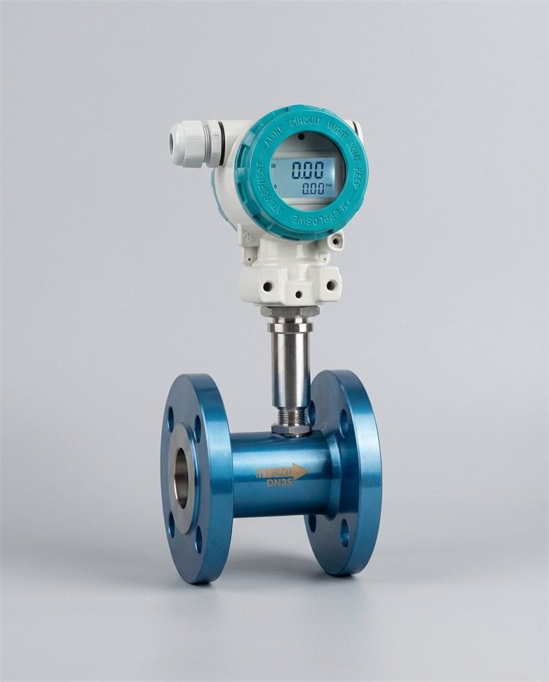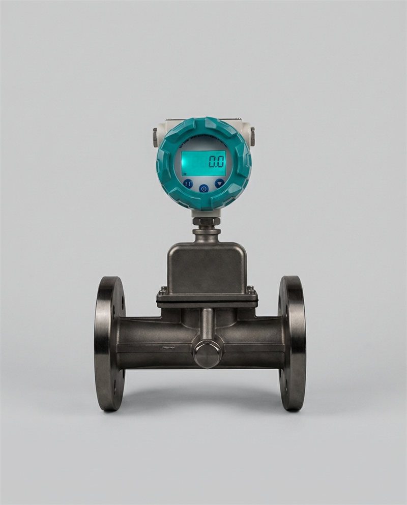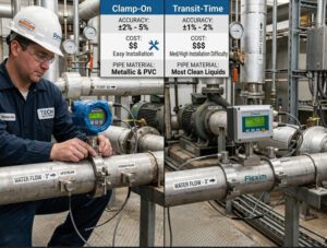

 Feature image: upload this file to your WordPress media library, then keep the filename above.
Selecting the optimal ultrasonic water flow meter requires a strategic alignment of measurement technology with specific fluid dynamics, piping infrastructure, and long-term operational goals. The buyer matches the technology, transit-time or Doppler, to the water in the pipe. The buyer then checks the pipe, the accuracy job, and the control system. This order protects measurement accuracy. This order also keeps lifecycle costs low and keeps the system reliable across industrial and municipal applications.
This guide speaks only to trade buyers. The guide serves OEM equipment and skid-mount manufacturers, instrument distributors and importers, EPC firms and system integrators, industrial end users and MRO teams, and municipal and utility operators. Each group buys meters for a different reason. The selection path in this guide respects each reason.
I. The Strategic Importance of Precise Flow Measurement
A. The Cost of Inaccuracy: How Improper Meter Selection Leads to Revenue Loss and Operational Inefficiency
A small error runs all day and all night. A meter that reads 2% low on a 500 m³/h line hides 10 m³ every hour. The utility loses 240 m³ of billed water in one day. The plant loses the same volume in process records and energy checks.
Selection errors cost more than lost volume. A distributor in the Middle East returned a batch of transit-time meters in 2024 after the site team found sand in the raw water line. The meters were sound. The fluid was wrong for the principle. Freight, re-testing, and a second site visit cost more than the meter margin.
Operations teams pay a third price. A wrong meter alarms at odd hours. The team stops trusting the reading. The team then runs the process by hand, and the plant loses the value of automation.
B. Overview of Ultrasonic Technology: Non-Invasive Measurement as a Solution for High-Maintenance Environments
An ultrasonic meter measures flow with sound waves. The meter sends sound through the water and reads how the flow changes the sound. The sensor does not spin, and the meter has no moving parts in the water path for clamp-on and most inline designs.
This design suits hard sites. The meter body does not touch corrosive water in a clamp-on build. The meter does not clog in a line with scale. The meter does not stop the line for a basic check.
Maintenance teams value one point most. The meter reports its own signal health. The team sees a weak signal before the team sees a wrong total.
C. Goal of the Guide: A Technical Framework for OEMs, EPCs, and Utility Managers to Select the Right Hardware for Diverse System Requirements
This guide gives a step-by-step selection framework. The framework starts with the fluid. The framework then moves to the pipe, the process, the accuracy job, the install, and the service life.
OEM teams can use the framework to freeze a standard meter for a skid line. EPC teams can use the framework to write a clean specification. Utility managers can use the framework to compare bids on equal terms. Readers who want the product range first can review the ultrasonic flow meter range from Jade Ant Instruments and then return to the framework.
 Replace this slot with your own chart or diagram. Suggested: survey-style pie chart of the five factors trade buyers weigh first in meter selection.
II. Understanding the Technology: Transit-Time vs. Doppler
A. Transit-Time Meters: Ideal for Clean Liquids and High-Precision Requirements
A transit-time meter sends sound both ways between two transducers. A transducer is a sensor that sends and receives sound. Sound moves faster with the flow and slower against the flow. The meter reads the time gap and turns the gap into flow velocity.
Clean water carries the sound with little loss. Treated water, potable water, and clean cooling water suit this principle well. Good transit-time meters reach ±0.5% of reading in an inline build. The principle also reads very low flow, and the meter can confirm true zero at no flow.
Field rule: the water should look clear in a sample bottle. Visible grit warns the buyer away from transit-time.
B. Doppler Meters: The Solution for Aerated Liquids, Slurries, and High-Solid Content Fluids
A Doppler meter sends sound into the flow and listens to the echo. Particles and bubbles in the water reflect the sound. The moving particles shift the echo frequency. The meter reads the shift and turns the shift into flow velocity.
This principle needs reflectors in the water. Raw water, wastewater, and slurry give the meter plenty of echoes. Very clean water gives the meter almost no echo, and the reading fails.
Doppler accuracy sits lower, near ±1% to ±2% of reading in good conditions. The trade-off makes sense for dirty water. A transit-time meter on the same line may give no stable reading at all.
Watch this short explainer on how ultrasonic metering technology works in water service:
https://www.youtube.com/watch?v=R1QogMjd2pY
C. Decision Matrix: Choosing Based on Fluid Conductivity and Particulate Matter
One note first: ultrasonic meters do not need fluid conductivity. Conductivity is a rule for magnetic meters, not for ultrasonic meters. The buyer chooses by particles, bubbles, and cleanliness instead.
| Question about the fluid | If the answer is yes | Best first choice |
|---|---|---|
| Does the water look clear, with no visible solids? | Sim | Transit-time |
| Does the water carry sand, silt, or fibre? | Sim | Doppler |
| Does the water hold steady air bubbles? | Sim | Doppler |
| Does the job need accuracy better than ±1%? | Sim | Transit-time, inline |
| Does the water change between clean and dirty by season? | Sim | Pilot test both principles |
| Does the line carry chemicals that attack wetted parts? | Sim | Clamp-on build, either principle |
Distributors can deepen this step with the side-by-side Doppler and transit-time explainer before they quote a mixed-fluid site.
III. Matching Meter Type to Pipe Geometry and Size
A. Inline vs. Clamp-on: Balancing Permanent Installation Stability with the Flexibility of Non-Invasive Mounting
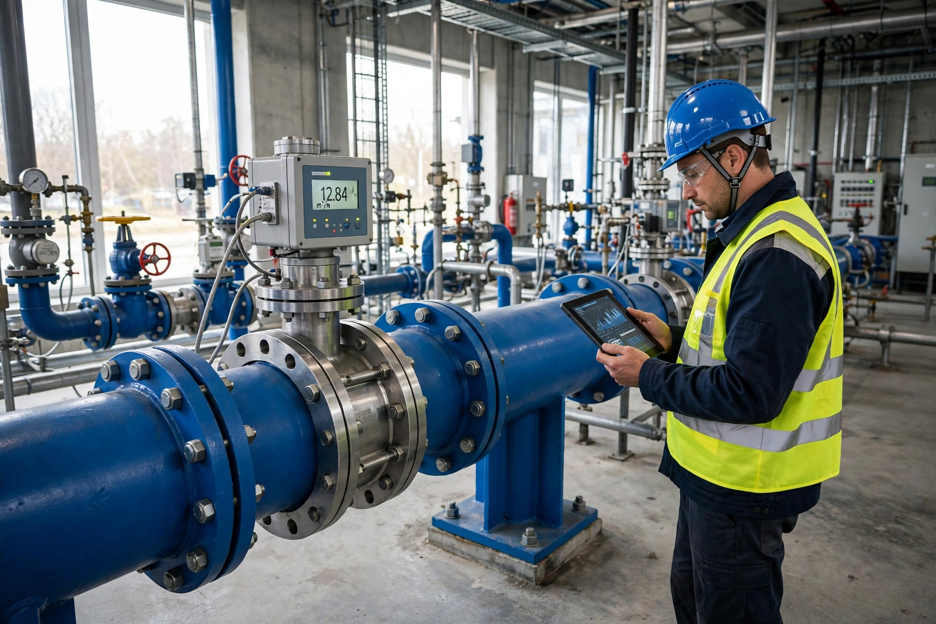
An inline meter forms part of the pipe. The crew cuts the line and bolts the meter body between flanges. The flow path stays straight and known, and the accuracy stays stable for years. Billing and custody jobs favour this build.
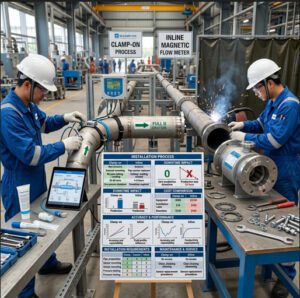
A clamp-on meter sits on the pipe wall. The crew straps the sensors on the outside and adds coupling gel between the sensor and the pipe. The crew does not cut the pipe and does not stop the process. Retrofit and audit jobs favour this build.
The cost picture differs. The inline meter costs more on install day. The clamp-on meter costs more in repeat checks if the site team moves sensors often. Buyers can compare both paths in the clamp-on versus inline buyer guide before they fix a project budget.
 Replace this slot with your own photo. Suggested: flanged inline ultrasonic meter on a stainless steel pipe in a clean utility room.
B. Scaling for Diameter: Addressing the Challenges of Very Small Bores Versus Large-Diameter Municipal Mains
Small pipes punish poor sensor fit. A DN15 line leaves little room for a clamp-on sensor, and a small air gap kills the signal. Compact inline meters serve small bores better. OEM skids often use DN15 to DN50 meters for dosing and cooling loops.
Large pipes punish poor signal planning. A DN1200 main needs strong transducers and a long, clear sound path. Multi-path meters serve large mains better because the meter reads several chords across the flow profile. One path can drift while the meter still reports a sound average.
Mid-size lines from DN50 to DN300 give buyers the widest choice. Both builds work well in this range, and price and shutdown windows decide the pick.
C. Material Compatibility: How Pipe Wall Thickness and Material (PVC, Steel, HDPE) Affect Signal Penetration
Sound must cross the pipe wall twice. The wall material and the wall thickness shape the signal.
| Pipe material | Signal behaviour | Practical note |
|---|---|---|
| Carbon steel | Sound crosses well | Remove loose rust and thick paint at the sensor spot |
| Stainless steel | Sound crosses well | Thin walls give a strong, clean signal |
| PVC | Sound crosses well | Enter the exact wall thickness in the setup |
| HDPE | Sound fades more | Use lower-frequency transducers and firm coupling |
| Cast iron | Sound scatters | Clean the spot well and expect a weaker signal |
| Lined pipe | Liner can block sound | Test the liner bond before you promise accuracy |
Thick walls need lower sound frequency. Low frequency travels farther through the wall and the water. The meter setup needs the true wall thickness, the true inner diameter, and the true pipe material. A wrong entry shifts every reading.
Buyers who face mixed pipe stocks can check the fluid and pipe compatibility notes for ultrasonic meters before they standardise one sensor type.
IV. Analyzing Fluid Conditions and Process Variables
A. Temperature and Pressure: Ensuring Sensor Durability and Signal Stability Under Extreme Conditions
Heat changes the speed of sound in water. A good meter measures water temperature or takes a temperature input and corrects the reading. Buyers should check the sensor rating against the real line temperature, not the design sheet alone.
Pressure rarely harms an ultrasonic reading. Pressure does test the meter body and the flanges on an inline build. The buyer matches the pressure class, such as PN16 or PN25, to the line rating. Clamp-on sensors avoid this test because the sensors never touch the water.
Steam-adjacent lines need care. A sensor rated to 120°C fails early on a 150°C return line, and the failure looks like random signal loss.
B. Flow Profile Management: The Role of Straight-Run Requirements and Flow Conditioners in Eliminating Turbulence
Water needs distance to settle after a bend, a valve, or a pump. This settled state is a stable flow profile. A common rule asks for 10 pipe diameters of straight pipe before the meter and 5 diameters after the meter. One diameter means one times the pipe inner width.
A disturbed profile bends the reading. A meter placed right after a 90° elbow can read several percent off, and the error changes with flow rate. This pattern confuses operators because the meter looks fine at one flow and wrong at another.
A flow conditioner can help on tight sites. The conditioner is a plate or tube bundle that evens the flow. The device costs pressure, so the engineer checks the pump head before the team adds one.
C. Viscosity and Density: Assessing the Impact of Fluid Properties on Sonic Velocity
Viscosity is the thickness of a fluid. Honey has high viscosity, and water has low viscosity. Water lines change viscosity with temperature, and cold water flows thicker than warm water. The change stays small for water, and most water meters handle the change with ease.
Density matters for mass reporting. An ultrasonic meter measures volume flow. The control system can multiply volume by density to report mass. The buyer confirms who owns that math, the meter or the SCADA system, before commissioning day.
Glycol mixes deserve a pilot test. A 30% glycol loop changes sound speed enough to shift an unchecked setup.
V. Evaluating Accuracy Standards and Calibration Needs
A. Precision Tiers: Differentiating Between Custody Transfer Accuracy and General Process Monitoring
Not every job needs the best tier. Buyers pay for accuracy they never use when they over-specify a simple alarm point.
| Job type | Typical accuracy need | Common meter choice |
|---|---|---|
| Custody transfer and billing | ±0.5% or better | Multi-path inline transit-time |
| District metering and leak zones | ±1% | Inline or fixed clamp-on transit-time |
| Controle de processos | ±1% | Inline transit-time |
| Energy and balance checks | ±1% to ±2% | Clamp-on transit-time |
| Wastewater and slurry lines | ±2% | Doppler |
| Site audits and spot checks | ±2% | Portable clamp-on |
Billing work also follows legal rules. The ISO 4064-1:2024 standard for water meters sets the metrology frame for cold and hot potable water meters. Buyers in regulated markets align the meter class with this frame.
B. Field Calibration: The Importance of “Wet” Calibration and Onsite Verification to Reduce Downtime
A wet calibration tests the meter with real water on a test rig. The rig compares the meter against a reference volume or a master meter. This test proves the full chain, sensor, cable, and transmitter.
Onsite verification checks the meter in place. The technician confirms zero at no flow, checks signal strength, and compares a portable reference meter. The line keeps running during most checks, and the plant avoids a shutdown.
EPC teams should write both duties into the contract. The factory supplies a wet calibration certificate. The site team repeats verification after install, because transport and mounting can shift a good meter.
C. Drift and Stability: Evaluating Long-Term Signal Stability to Minimize Frequent Re-Calibration
Ultrasonic meters drift less than mechanical meters. No rotor wears down, and no bearing adds friction year by year. The main drift sources are scale on a sensor face, a moved clamp-on sensor, and aged coupling gel.
Signal trend logs expose slow drift early. The meter stores signal strength and gain values. A steady fall in signal strength tells the team to clean or re-couple the sensor before the reading suffers.
Buyers should ask for drift data across a full year, not a one-week trial. Seasonal temperature swings reveal weak sensor designs.
VI. Installation Engineering: Reducing CAPEX and OPEX
A. Mounting Configurations: Optimizing Sensor Placement for Maximum Signal Strength
Clamp-on sensors mount in two main patterns. The V pattern bounces the sound once off the far wall and suits small and mid pipes. The Z pattern sends sound straight across and suits large pipes and weaker signals.
The crew cleans the pipe spot to bare, sound material. The crew applies gel evenly and sets the sensor spacing from the transmitter guide. A 2 mm spacing error on a small pipe can cost clear accuracy.
Inline meters need correct gasket fit and full pipe conditions. The meter must run full of water. A top-of-riser mount can trap air, and trapped air breaks the sound path.
 Replace this slot with your own photo. Suggested: technician fitting clamp-on sensors with coupling gel on a large HDPE pipe outdoors.
B. Power Supply Options: Comparing Battery-Powered Remote Sites vs. Hard-Wired Industrial Skids
Battery meters serve sites with no mains power. District zones, rural pump points, and irrigation offtakes use this build. A good battery meter runs 6 to 10 years on one pack at a modest reading rate. Faster logging shortens that life, and buyers should model the real logging plan.
Hard-wired meters serve plants and skids. A 24 V DC loop suits control panels, and mains power suits pump halls. Wired power also supports fast data rates and bright displays with no energy budget.
Solar charging extends remote life on sunny sites. The panel adds theft and shading risks, so the utility weighs site security before the team chooses solar.
C. Integration Requirements: Ensuring Compatibility with PLC, SCADA, and IoT Ecosystems (4-20mA, Modbus, HART)
A meter earns its keep when the data reaches the control room. The buyer names the output before the order, not after delivery.
| Output | What it does | Best fit |
|---|---|---|
| 4-20mA | Sends one flow value as a current signal | Simple PLC loops and legacy panels |
| Pulse | Sends one pulse per set volume | Totalising, dosing, and billing heads |
| Modbus RTU/TCP | Sends many values over a data bus | SCADA systems and data loggers |
| HART | Adds digital data on a 4-20mA loop | Plants with HART asset tools |
| M-Bus / wireless | Sends meter data for reading networks | Utility AMR and AMI projects |
Most plants run a SCADA system, a central software platform that watches and controls the process. Buyers who plan a dedicated ultrasonic water flow meter line for utility work should confirm the reading protocol at order stage. Protocol swaps after delivery cause the most common integration delay that integrators report.
 Replace this slot with your own photo. Suggested: wall-mounted flow transmitter linked to a SCADA screen with flow trend graphs.
VII. Maintenance and Lifecycle Management
A. Reducing Total Cost of Ownership (TCO): Comparing the Maintenance of Ultrasonic Meters vs. Mechanical Meters
Purchase price is one line in a ten-year ledger. Install labour, calibration, spare parts, and downtime fill the other lines. A turbine meter often wins the first line and loses the ledger.
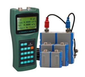
A turbine rotor wears in sandy water. The plant then pays for rebuild kits, recalibration, and lost data during each repair. An ultrasonic meter on the same line pays for sensor checks and little else. Site teams that run portable ultrasonic meters for water audits and leak checks often find the lost-water savings first, and the savings then fund the fixed meter upgrade.
 Replace this slot with your own chart or diagram. Suggested: ten-year cost build-up chart, purchase, install, maintenance, calibration, and downtime, ultrasonic versus turbine.
B. Diagnostic Capabilities: Leveraging Built-In Signal Quality Indicators for Predictive Maintenance
Modern meters report signal strength, gain, and transit-time health. These values form an early warning set. A rising gain value means the meter works harder to hear the signal, and fouling or bubbles may grow in the line.
Maintenance teams can trend three values each month:
- Signal strength per path.
- Zero-flow offset at a known stop.
- Difference between paths on a multi-path meter.
A team that trends these values fixes causes, not symptoms. The team also walks into calibration visits with proof, and the visit takes hours, not days.
C. Wear and Tear: Addressing the Longevity of Transducers in Corrosive or Abrasive Environments
Inline transducers face the water. Chloride-rich water can pit poor steel grades over years. Buyers in coastal plants should ask for 316L wetted parts or better.
Clamp-on transducers face weather, not water. Sun, rain, and vibration age the housing and the cable. IP68-rated sensors suit buried and flooded chambers. A flooded chamber kills an IP65 sensor in one season.
Abrasive flow rarely harms an ultrasonic meter because the meter has no moving parts in the stream. Scale can coat a sensor face, and a simple cleaning plan prevents signal loss.
VIII. Procurement Strategies for OEMs and EPCs
A. Standardization: Creating a “Preferred Vendor” List to Simplify Spare Parts Management Across Multiple Projects
One meter family across many projects cuts spare stock. The warehouse holds one sensor type, one cable type, and one transmitter type. Field teams learn one menu system and one fault list.
OEM builders gain the most. A skid builder who freezes one meter model can pre-wire panels, pre-print manuals, and train service staff once. Jade Ant Instruments supports this model with a skid-mounted flow meter selection guide for OEM builds, and project teams can cite that guide in a vendor freeze memo.
Distributors gain a second benefit. A short preferred list shortens quote time. The sales engineer stops re-checking basic fit on every enquiry and spends time on the hard sites.
B. Lead Time Management: Strategies for Sourcing Meters Without Delaying Project Commissioning
Meters delay projects when buyers order late or specify rare options. Flanged large-bore bodies and special liners carry the longest lead times. Standard clamp-on sets and common inline sizes ship far faster.
Three habits protect the schedule:
- The buyer freezes pipe data at design stage, not at order stage.
- The buyer orders long-lead bodies with the pipe spools.
- The buyer books factory calibration slots with the purchase order.
EPC planners should also hold one portable meter at site. The portable unit covers any gap and verifies installed meters at handover.
C. Compliance and Certification: Navigating MID, OIML, and ISO Standards for Regulatory Approval
Billing meters in Europe need MID approval under the Measuring Instruments Directive. The approval proves the meter meets legal accuracy and durability rules for trade use.
OIML R 49 is the global test frame for water meters. Buyers can browse the OIML list of international recommendations to confirm the current R 49 edition and its scope. Test labs align reports to this frame, and tender teams often cite the report number in bid files.
ISO 4064 mirrors the same technical ground for potable water meters. Hazardous-area sites add ATEX or IECEx needs, and wet chambers add IP68 proof. Buyers should list each needed certificate in the RFQ, because a missing certificate can void an otherwise sound bid. General background from a major maker, such as the Fuji Electric note on how an ultrasonic meter works, helps junior engineers prepare for these tender talks.
IX. Application Case Studies: Solving Real-World Pain Points
A. OEM/Skid-Mount: Integrating Compact Meters into Tight Footprints for Modular Equipment
A skid builder in Southeast Asia packed a cooling-water skid into a 1.2 m frame. The design had no room for long straight runs. The team chose a compact inline transit-time meter with a vendor-supplied flow profile test at the skid layout.
The meter held ±1% in factory tests at three flow points. The builder then froze the model for 40 repeat skids. Service calls on flow faults fell to near zero in the first year, and the builder traced the gain to the fixed meter position and the fixed pipe layout.
Lesson: tight skids need the meter and the pipe designed as one unit. A late meter swap breaks both.
B. Municipal/Utility: Managing Leak Detection and Billing Accuracy in Large-Scale Water Distribution
A city utility split one supply zone into eight district metered areas. A district metered area is a zone with measured inflow, so night use reveals leaks. The utility fitted battery inline ultrasonic meters at each inlet and logged flow every 15 minutes.
Night flow in one zone stayed high for six weeks. Crew checks found a slow main leak under a paved yard. The repair cut zone losses by about 9% in the next quarter, based on the utility log. Billing totals also rose in accuracy because the new meters read low night flows that the old mechanical meters missed.
Lesson: low-flow skill matters as much as full-flow accuracy in leak work. Old meters often under-read the small flows that expose leaks.
C. Industrial MRO: Replacing Obsolete Mechanical Meters with Non-Invasive Ultrasonic Upgrades
A food plant ran 14 ageing turbine meters on wash-water lines. Two lines could not stop for pipe work during the season. The MRO team fitted clamp-on transit-time meters on the two live lines and inline meters on the rest during a planned stop.
The clamp-on units matched the new inline units within ±2% during a joint test week. The plant kept both sets. Plant staff now verify the inline meters with the clamp-on sets each year, and the team no longer sends meters away for basic checks. A Badger Meter clamp-on FAQ page gives a plain overview of the same retrofit logic for facility teams.
Lesson: a mixed fleet can beat a single-build fleet. The clamp-on units pay for themselves as in-house check tools.
X. Finalizing the Selection Framework
A. Summary of the Technical Selection Process
The selection path has a clear order. The buyer identifies the fluid first. The buyer matches the principle, transit-time or Doppler, to that fluid. The buyer then fits the pipe size, the material, and the install window. The buyer sets the accuracy tier, the outputs, and the power plan. The buyer closes with service, spares, and certificates.
Each step removes options. A buyer who follows the order reaches a short list fast and defends the pick with facts.
B. The Synergy Between Hardware Capability and Application Environment
No meter wins on the datasheet alone. A high-spec meter fails on a dirty line if the principle is wrong. A modest meter serves for years when the fluid, the pipe, and the job align. The site makes half the accuracy, and the install team makes the other half real.
Smart buyers test in the real environment. A one-week pilot on the actual line beats a month of desk debate.
C. Final Call to Action: Consulting Technical Datasheets and Conducting Pilot Tests
Project teams should send five data points with any enquiry: fluid type, pipe size and material, flow range, temperature, and needed output. Readers can ask the Jade Ant Instruments team for a datasheet review with those five points in the first message. The review returns a principle pick, a size pick, and a pilot test plan. A pilot test on one line then proves the pick before a fleet order.
Glossary: Plain Words for Key Terms
| Termo | Plain meaning | Example |
|---|---|---|
| Transducer | A sensor that sends and receives sound in the water | A clamp-on meter uses two transducers on the pipe wall |
| Transit-time | A method that reads the time gap of sound with and against flow | Clean treated water in a DN100 steel line |
| Doppler shift | A change in echo frequency from moving particles | Sand in raw water shifts the echo and reveals flow |
| Straight run | A length of straight pipe with no bends or valves | 10 diameters before the meter on a DN200 line means 2 m |
| Relação de redução | The span between the highest and lowest flow a meter reads well | A 100:1 turndown reads 1 to 100 m³/h on one meter |
| Transferência de custódia | Flow measurement used to bill money between parties | A utility inlet meter that sets a bulk water invoice |
| Wet calibration | A test with real water against a reference standard | A rig test at 3 flow points with a master meter |
| SCADA | A central system that watches and controls a plant or network | Operators watch zone flows and alarms on one screen |
| IP68 | A rating that allows long immersion in water | A sensor that keeps working in a flooded chamber |
| TCO | Total cost of ownership across the full service life | Purchase plus install, service, calibration, and downtime |
Perguntas frequentes
1. How do I determine if my fluid requires a Transit-time or Doppler meter?
The buyer checks the water first. Clear water with no visible solids suits a transit-time meter. Water with sand, silt, fibre, or steady bubbles suits a Doppler meter. A sample bottle test gives a fast first answer. A short pilot test gives the final answer on mixed fluids.
2. What is the minimum straight-run requirement for an ultrasonic meter to ensure accuracy?
Most makers ask for 10 pipe diameters before the meter and 5 diameters after the meter. Tight sites can use less distance with a flow conditioner or a vendor profile test. Custody jobs should keep the full distance. A meter too close to a bend can read several percent off.
3. Can clamp-on ultrasonic meters be used on lined pipes or composite materials?
Yes, with care. The liner must bond tight to the pipe wall with no air gap. A loose liner blocks sound and breaks the reading. The technician should test one spot with a portable meter first. Composite pipes need the true wall build in the setup, layer by layer.
4. How does the presence of air bubbles (entrained air) affect ultrasonic measurement?
Small amounts of fine bubbles weaken a transit-time signal. Large air pockets can stop the reading. Doppler meters use bubbles as reflectors, so light aeration helps a Doppler meter. Air at the top of a pipe is a common fault, and a full pipe mount point avoids the trap.
5. What is the typical lifespan of an ultrasonic transducer in a municipal water system?
A fixed transducer often serves 10 to 15 years in clean municipal water. The transmitter electronics may need one refresh in that span. Flooded chambers and harsh sun shorten sensor life. IP68 sensors and shaded mounts protect the full term.
6. How do I integrate an ultrasonic flow meter into an existing SCADA system?
The engineer picks the output that the SCADA system already reads. Modbus suits most modern systems and carries flow, total, and alarms in one link. A 4-20mA loop suits simple sites and carries flow only. The team confirms register maps and scaling before commissioning day.
7. Which is more cost-effective over 10 years: an inline ultrasonic meter or a mechanical turbine meter?
An inline ultrasonic meter wins most 10-year comparisons on water lines with sand, scale, or long service needs. The turbine meter costs less at purchase. The turbine then adds rebuilds, recalibration, and downtime. Clean, small, low-duty lines can still favour a turbine meter on cost.
8. Do ultrasonic meters require a specific fluid velocity to maintain accuracy (low-flow limits)?
Yes. Each meter has a low-flow limit, often near 0.01 to 0.03 m/s for transit-time models. Below that limit, the meter may read zero or drift. Buyers in leak zones should check the limit against real night flow. A wide turndown ratio protects low-flow work.
9. How can I verify the accuracy of a clamp-on meter without removing it from the pipe?
The technician checks four points in place. First, the technician confirms zero at a true no-flow stop. Next, the technician checks signal strength against the install record. Next, the technician compares a second portable meter at a nearby spot. Last, the technician reviews total flow against pump curves or tank level change.
10. How often should ultrasonic meters be recalibrated in a high-precision industrial process?
High-precision plants verify meters once a year and recalibrate on a 2 to 3 year cycle, or sooner if checks drift. Legal billing points follow the local metrology rules, which can set firm test dates. Trend logs guide the plan. A stable signal trend supports a longer cycle, and a falling trend calls for an early visit.