Clamp-On Ultrasonic Flow Meter Troubleshooting: Fix the Signal First
Most clamp-on meters do not fail in one day. The signal weakens, the reading wanders, and someone blames the electronics. Most of the time the fault sits at the pipe wall. This guide runs the checks in the order that finds it fastest.

Why clamp-on ultrasonic flow meter troubleshooting starts at the pipe wall
A clamp-on meter runs on one thing: sound. It sends a pulse through the pipe wall, into the liquid, and listens for the return. Every number on the display depends on that echo arriving clean.
When the echo weakens, the meter does not stop. It keeps calculating. It reuses the last good value, or it averages noise. So the first symptom is usually a slow drift, not an alarm.
That is what makes these faults expensive. A crew drives to site, opens a panel, and finds nothing wrong inside. The problem is a dried layer of gel on a transducer face.
Each buyer feels that cost in a different place. OEM and skid-mount builders see a warranty callback. Instrument distributors and importers see a support case they cannot bill.
EPC and system integrators see a delay on the commissioning certificate. Industrial terminal and MRO teams see a night shift on a ladder. Municipal and utility crews see a billing number they cannot defend.
Jade Ant Instruments sells to all five groups. The same pattern shows up in every one of them. The meter is rarely the weak point.
One site visit to a remote pump station often costs USD 600 to 1,200 in labour and travel before any part is replaced. That is an illustrative figure. Keep it in mind, because most of those visits are avoidable.
The checks below follow one order: diagnose, couple, align, validate. Skipping a step costs more time than it saves. Clean the pipe before you change the gain. Confirm the spacing before you open the manual.
The physics takes one page to explain. How clamp-on meters measure without cutting the pipe covers the transit-time path and the limits that come with it. Water utilities can benchmark their own loss figures against the American Water Works Association water audit guidance.
Read the diagnostics before you reach for a wrench
Signal strength and signal quality are two different numbers. Mixing them up is the most common diagnostic mistake in the field.
Quick definition: signal strength — also called gain, amplitude, or AGC. It shows how hard the receiver works to amplify the returning echo. On many meters a low number means a hard-working receiver, so read your manual before you judge.
Quick definition: signal quality — also called stability. It shows how steady the transit time stays from pulse to pulse. A strong echo can still arrive at the wrong moment.
Quick definition: signal-to-noise ratio (SNR) — the size of the real echo compared with the electrical and acoustic noise around it. You can have 80% strength and a poor SNR at the same time.
The pair tells you where to look:
| What the meter shows | What it usually means | First thing to check |
|---|---|---|
| Strong signal, flow jumps 10–20% | Good echo, unstable timing | Cable route, ground loops, nearby drives |
| Weak signal, steady flow | Poor acoustic path | Couplant, surface finish, spacing |
| Signal falls when a pump starts | Vibration or electrical noise | Damping, cable separation |
| Signal falls as flow rises | Air bubbles or swirl | High points, upstream fittings |
| Signal fine, reading wrong | Geometry or fluid data entry | Pipe OD, wall, liner, fluid |
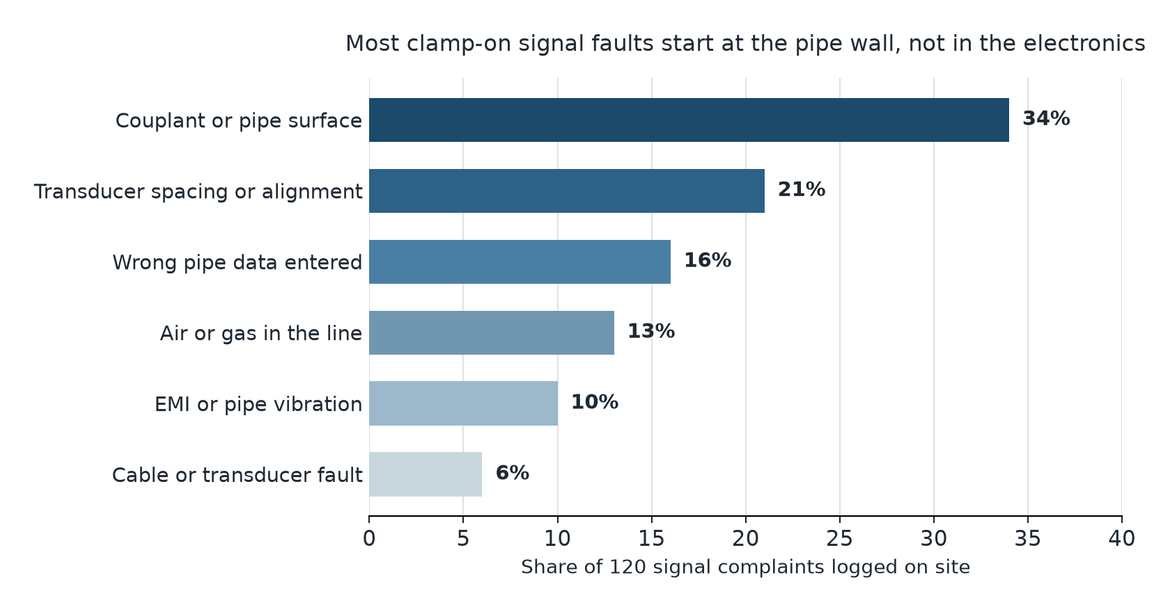
An illustrative split of 120 logged signal complaints puts about one third on coupling and surface condition, one fifth on spacing or alignment, and only 6% on cable or transducer faults. Use the chart to order your checks. Do not read it as a published statistic.
Electrical noise. Variable frequency drives switch at 2 to 8 kHz. That band sits close to the pulse rates many meters use.
Route the transducer cable at least 300 mm away from motor cables. Cross other cables at 90 degrees when you cannot avoid them. Ground the shield at one end only. Grounding both ends makes a loop, and the loop works like an antenna.
A drive that runs at 40 Hz today may run at 50 Hz next month. Noise faults appear after a production change, not after the meter was installed.
Air and cavitation. Free air absorbs ultrasound. A line carrying 1% to 2% entrained air can lose half its signal. Cavitation sounds like gravel in the pipe and often starts at a partly closed valve. Move the sensors away from the disturbance, or fix the air source.
Every service team has the same story. The meter was fine. The mounting was not.
Coupling: the 2 mm layer that decides everything
The transducer face and the pipe wall never touch. A thin layer of couplant fills the gap. That layer is the weakest link in the whole measurement.
Quick definition: acoustic impedance — how strongly a material resists the passage of sound. Steel is about 46 MRayl. Air is about 0.0004 MRayl. The gap between those numbers is why a pocket of air the thickness of a hair can bounce most of the pulse back.
A 0.1 mm air film inside the coupling layer can remove more than half the signal. The meter keeps working, with less gain margin. Then a hot week, a dry month, or a new coat of paint finishes the job.
Couplant choice follows temperature, not habit:
| Couplant | Practical range | Best for | Weak point |
|---|---|---|---|
| Silicone gel | −20 to 120 °C | Water, HVAC, general plant | Dries and cracks outdoors in 2–3 years |
| Lithium grease | −10 to 80 °C | Portable checks, short surveys | Runs off a hot pipe |
| High-temperature paste | up to 200 °C | Steam, hot process lines | Hard to clean off |
| Epoxy or solid pad | −40 to 150 °C | Permanent outdoor points | Cannot be reused |
Applying it well takes 30 seconds. Clean the pipe to bare metal. Put a 3 mm bead on the transducer face. Press and twist about 30 degrees as you seat it. Do not slide the transducer sideways once it touches, because sliding traps air.
Too much gel is as bad as too little. The gel has its own sound speed, and a thick layer adds a path you did not model.
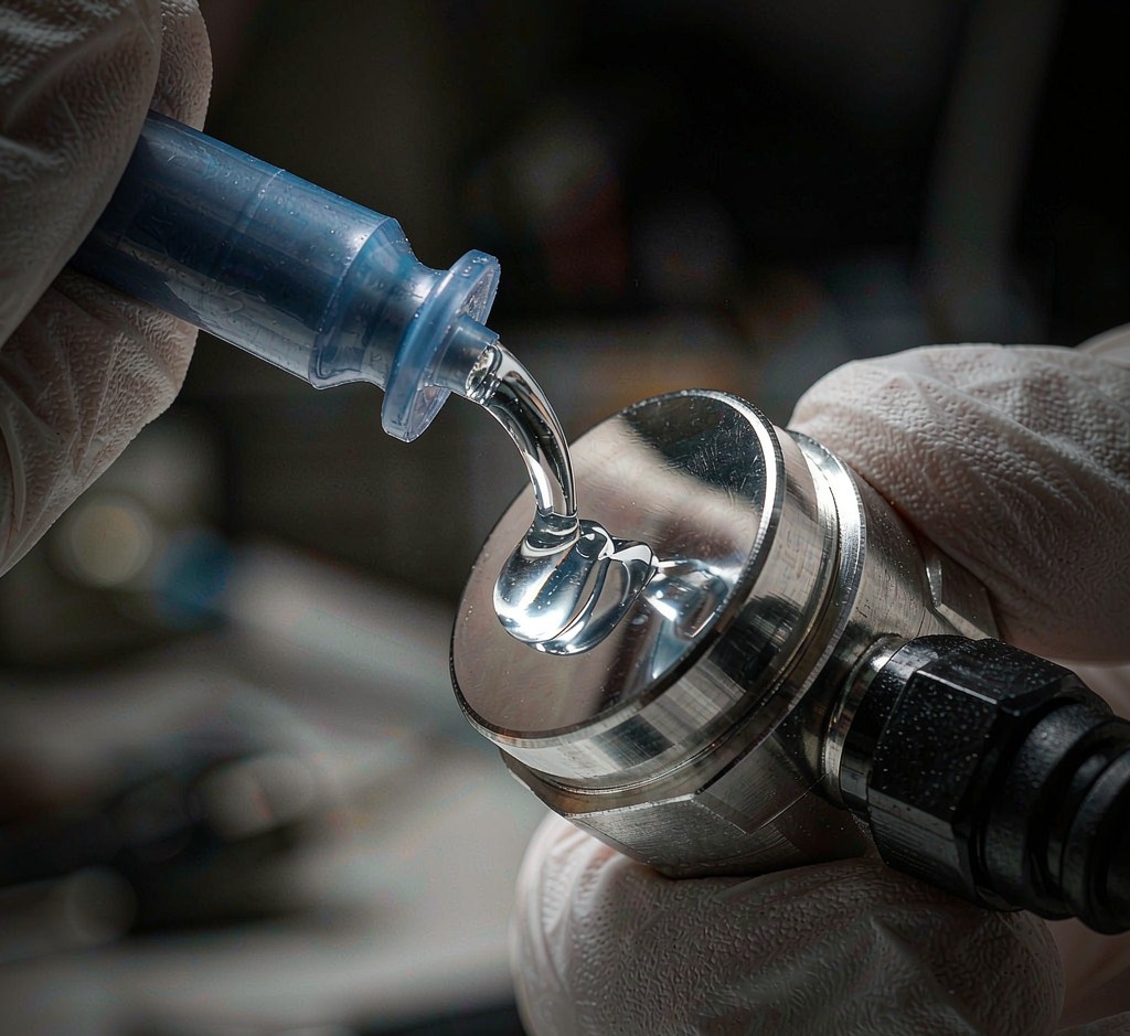
Surface condition decides the rest. Mill scale, loose rust, and thick paint all absorb or scatter sound. A flap disc on a grinder removes them in a minute.
The bare patch should be about 1.5 times the transducer footprint. Do not grind through the wall. On thin stainless, use a wire brush and a chemical cleaner instead.
For a permanent point, the surface routine decides whether you get a five-year sensor or a five-month one. The steps match general flow meter installation practice, with one addition. Mark the sensor positions with a paint pen before you lift them.
Mounting that survives heat, vibration, and gravity
A transducer that moves 2 mm has moved off its acoustic path. The reading drifts, and no menu setting brings it back.
Thermal growth is the usual culprit. Carbon steel expands about 12 µm per metre for every degree Celsius. A 6 m run between anchors grows roughly 7 mm over a 100 °C swing. If the sensor is held by a hand-tight strap, the pipe grows and the sensor stays. The path breaks.
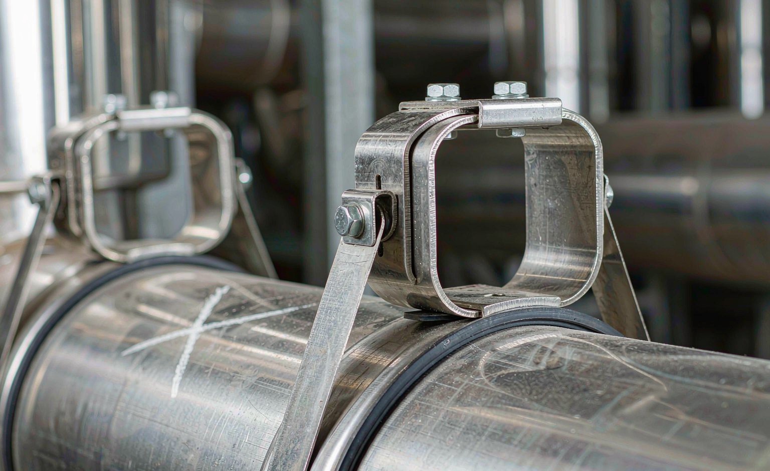
Rigid stainless brackets with a tension band hold position through that movement. Nylon straps do not. Chain is fine for a one-hour survey and wrong for a permanent point.
Vibration does the same damage faster. A sensor on a pump discharge line sees the impeller blade pass frequency all day. The clamp loosens, the couplant squeezes out, and the signal decays over weeks.
Add a 2 mm rubber damping pad between bracket and pipe. Keep the mounting at least 5 pipe diameters from a pump outlet. Avoid unsupported spans, where pipe movement is largest.
Pump and piping vibration limits appear in Hydraulic Institute standards, and those limits help when you argue for a better mounting location.
Clamp force has a ceiling. The piezo crystal inside a transducer is brittle. Over-tighten a plastic-bodied sensor and you crack it. The crack shows up as a slow loss of amplitude, with no visible damage outside.
For most plastic housings, 2 to 3 N·m is enough. If you have no torque wrench, tighten by hand and add a quarter turn. Stainless housings take more, so follow the datasheet.
Retrofit work on old plant adds one more constraint. The pipe may be out of round, pitted, or buried under insulation. Adding a meter to existing pipework usually means finding a straight, reachable section and accepting a small compromise on location.
The clip below shows a real mounting sequence. Watch how the installer sets the strap tension and where he leaves the cable slack.
https://www.youtube.com/watch?v=RkKJph285ik
Alignment: the millimetre that costs you 5%
Spacing is the distance between the two transducer faces along the pipe. Every meter calculates it from the pipe and fluid data you entered. Wrong data gives wrong spacing.
Quick definition: S-distance — the centre-to-centre spacing the transmitter calculates for your pipe, wall, material, liner, fluid, temperature, and transducer pair. It is not a fixed number. Change the wall thickness by 1 mm and it changes.
There are three mounting paths:
| Path | What the sound does | Where it fits |
|---|---|---|
| V | One reflection off the far wall | Most pipes from DN50 to DN600 |
| Z | Straight across, no reflection | Large pipe, thick wall, weak signal |
| W | Two reflections | Small pipe, thin wall, low flow |
The geometry error that hurts accuracy most is wall thickness. Take a DN100 line with a 114.3 mm outside diameter. A 6 mm wall gives a 102.3 mm bore. A 7 mm wall gives 100.3 mm. That 1 mm error changes the cross-section by 4%, and flow follows the area.
Spacing errors mostly cost amplitude, not accuracy. A 1 mm offset moves the receive point about 1 mm. At DN100 the beam footprint is roughly 15 to 20 mm wide, so the echo still lands. A 10 mm offset can push the beam off the receiver, and the signal collapses.
Straight run. Ten diameters upstream and five downstream is the common baseline. After two bends in the same plane, use 20 and 10. After two out-of-plane bends, or downstream of a partly closed valve, use 30 and 10. If the pipe run is short, move to the calmest section you have, accept a small bias, and write it down.
Non-standard pipe is its own problem. Composite and plastic pipe can be out of round, and wall thickness varies around the circumference. Measure at four points. This is where choosing the right sensor for the pipe matters more than any menu setting.
Taming the noise floor with settings, not guesswork
Electronics can hide a moderate amount of noise. They cannot invent signal.
Damping and integration time smooth the displayed value. Raising damping from 1 s to 30 s can cut visible scatter by about five times.
It also delays the response. A 30 s average will not show a short leak. It will not show a fast valve movement either.
The control loop starts to feel slow. Set damping to the shortest value the process allows, not the longest.
Zero-flow calibration removes a fixed offset. Do it in this order:
- Fill the pipe and confirm it stays full.
- Stop flow and isolate the line. A closed valve with a leaking bypass is not zero flow.
- Let the pipe sit 20 to 30 minutes so temperature settles.
- Run the zero routine and record the offset.
- Repeat once to confirm the number holds.
A 0.02 m/s offset sounds small. On a DN100 line it equals about 0.57 m³/h, which is 5,000 m³ a year on a line that never stops.
Set alarms on quality, not only on flow. Most transmitters offer a signal-strength or quality alarm. Wire it to the control system. An alarm at 40% signal gives you weeks to plan a visit. A dead signal gives you a shutdown.
| Setting | Raise it when | What it costs |
|---|---|---|
| Damping / response time | Reading is noisy but signal is strong | Slower response, hidden short events |
| Gain limit | Signal is weak but stable | More noise, more false echoes |
| Low-flow cutoff | Meter shows small flow at night | Real low flows report as zero |
| Signal alarm threshold | You want early warning | More nuisance alarms during transients |
Signal processing also differs by meter type. A Doppler meter reads dirty liquid that a transit-time meter cannot handle, and it processes the return in a different way. If your fluid carries solids, the fix may be a different principle, not a better mounting job.
On the output side, HART remains the common way to pull diagnostics into an asset system without new wiring. The HART Communication Foundation specification lists the device variables and status flags a host can read.
Check the pipe before you blame the meter
Some pipes never carry a good signal, however careful the installation is. Knowing which ones saves a wasted trip.
Sound loses energy as it crosses steel. Thick walls, rough surfaces, and some linings absorb more of it. Transducer frequency sets the trade-off.
Lower frequency reaches further but resolves less detail. Higher frequency gives a cleaner echo on small, clean pipe and dies quickly in a thick wall.
A rough guide:
| Pipe | Typical behaviour | What to do |
|---|---|---|
| Carbon steel, clean, 3–10 mm wall | Strong signal, easy install | Standard 1 MHz or 2 MHz pair |
| Stainless steel, 6–12 mm | Slightly weaker, still workable | Clean surface, more couplant |
| Cast iron, 10–20 mm | Signal scattered by graphite flakes | 1 MHz pair, Z-path, short spacing |
| HDPE or PVC | Good signal, wall varies | Measure wall at four points |
| Cement-lined steel | Very weak, often unusable | Different technology or location |
| Rubber or epoxy lined pipe | Liner absorbs or bends the beam | Test on site before you buy |
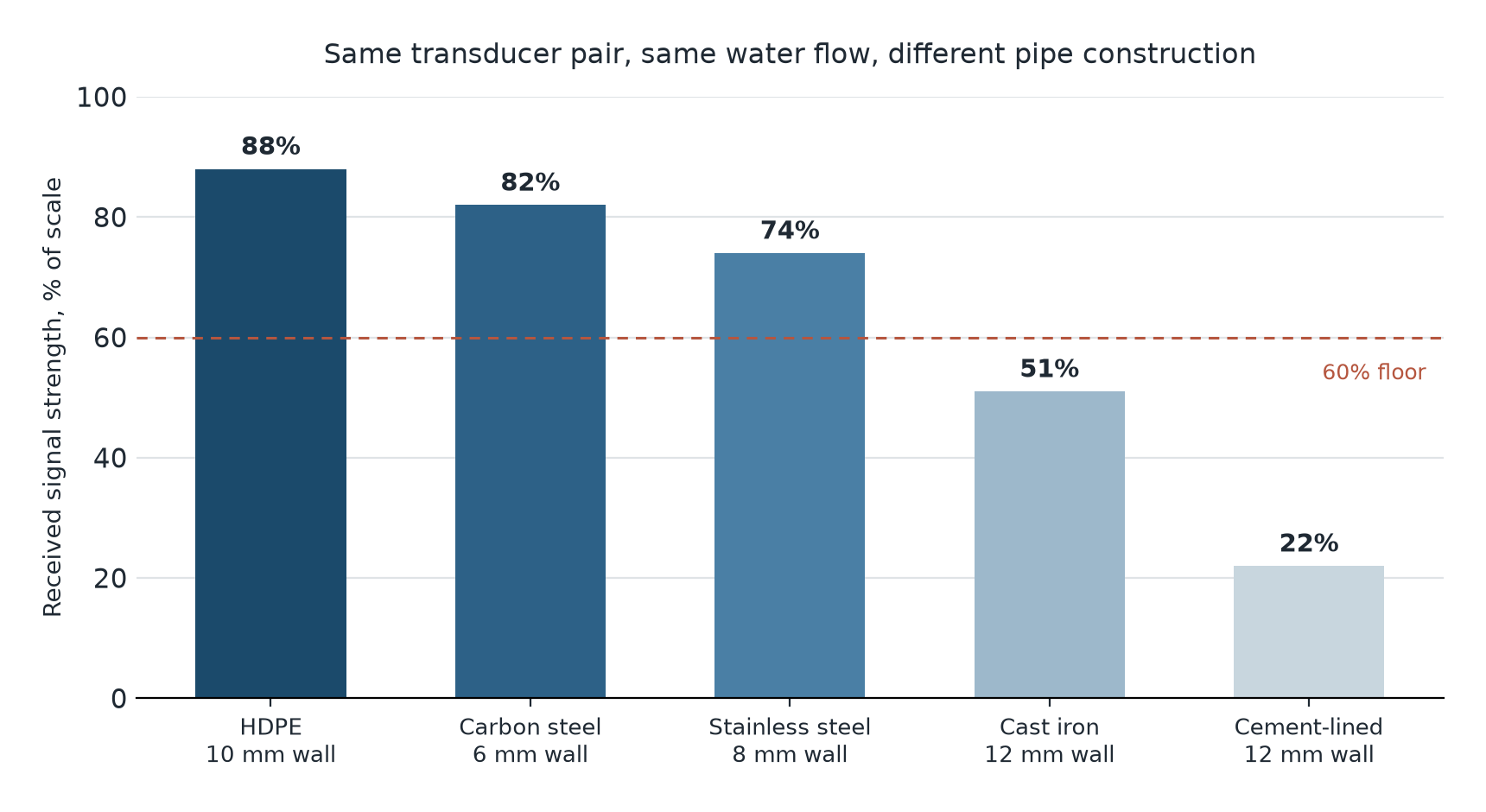
An illustrative test of one transducer pair on five pipe types shows 22% signal on cement-lined steel against 88% on HDPE. Same water, same flow, same electronics. The pipe decided the result.
Dead zones. A weld bead, a flanged joint, or a valve body within five diameters distorts the flow and can block the path. Internal scale does the same. A 3 mm scale layer changes the bore and the acoustic path at once, and the meter has no way to know.
That is why a meter can read well for two years and then drift. Nothing in the electronics changed. The inside of the pipe did.
Cleaning the outside fixes more cases than any menu adjustment. The photograph below shows the routine: bare metal, correct patch size, nothing loose left under the sensor.

Check the fluid as well as the pipe before you commit to a location. Aerated water, slurries, and chemical solutions each treat the acoustic path differently, and the fluid compatibility guide lists what each one does.
Transducer pairs also need to match. A mismatched pair shows up as a weak signal. No amount of gel will fix it. Jade Ant Instruments matches pairs before they leave the factory.
Recalibrate or remount? Decide with two questions
Two questions separate an electronic fault from a mechanical one. Did the signal change, and how fast?
| Symptom | Likely cause | Action |
|---|---|---|
| Signal drops from 80% to 20% in a day | Couplant dried, sensor moved, cable damaged | Remount, do not recalibrate |
| Signal steady, reading drifts over months | Zero offset, or bore changed by scale | Zero check, then compare |
| Reading falls to zero at night | Air pocket at a high point, low flow | Move sensors, add air release |
| Good signal, reading off by 8–12% | Pipe data entry error | Re-enter OD, wall, liner, fluid |
| Random spikes, stable average | Electrical noise | Cable route, single-end shield ground |
| Reading shifts when a second pump runs | Flow profile change or swirl | More straight run, or record the bias |
Recalibrate when the signal is healthy. A stable signal with a slow offset points to electronics or to a changed bore. Start with a zero check. If the offset survives a proper zero, compare against a second reference before you touch the calibration constants.
Remount when the signal moved. A sudden 60-point drop in strength is mechanical. A new transmitter will not fix it.
For municipal networks, put the check on a calendar instead of waiting for a complaint. An annual zero check and a three-year full validation match the rhythm of most utility asset plans.
The same data feeds the records used for water and wastewater flow management. A utility may need to prove traceability to a regulator. The National Institute of Standards and Technology keeps the reference standards that calibration labs work back to.

The cost argument is simple. A planned remount takes an hour with the line running. An unplanned failure takes a crew, a shutdown window, and a report to whoever owns the billing number.
Design the failure out: what OEMs and EPCs can fix early
Most field faults are decided in the drawing office. A skid built with a repeatable mounting jig does not produce spacing errors. A plant commissioned with a written gate check does not produce data-entry errors.
Build a jig. One laser-cut bracket that sets the S-distance for the pipe size you build most often removes the variable. The jig costs a few hundred dollars. One callback on a remote skid costs two days, a flight, and a customer’s confidence.
Write the gate check. Five items catch most of what goes wrong:
| Gate | Pass condition | Who signs |
|---|---|---|
| Surface | Bare metal, patch 1.5× transducer footprint | Installer |
| Couplant | Fresh, 2–3 mm, no visible voids | Installer |
| Spacing | Matches the value the meter calculated | Commissioning engineer |
| Data entry | OD and wall measured, not copied from a drawing | Commissioning engineer |
| Signal | Above the site minimum, stable for 10 minutes | Commissioning engineer |
Turn on remote diagnostics. A transmitter that reports signal strength to the control system turns a mystery into a trend. You see the decline before the reading fails. On distributed systems, that is the difference between a planned visit and an emergency call.
Skid builders and integrators ask for two things. They want a mounting pattern that repeats. They also want a signal number they can put in a commissioning report.
Those are reasonable demands. They are also where flow monitoring on integrated systems either works or turns into a support queue.
Clamp-on troubleshooting is a sequence, not a search. Read the diagnostics first. Fix the coupling.
Confirm the geometry. Validate against a second reference. Each step removes a class of causes. The order keeps you out of the menu until the physics is right.
The economics follow the same logic. A transducer pair mounted properly runs for years without attention. One strapped on in a hurry produces callbacks, drifting numbers, and reports nobody trusts.
The purchase price is a small part of the total cost of ownership. The installation is the rest of it.
If a line is giving you a weak or unstable reading, send the details: pipe outside diameter, wall thickness, material, liner, fluid, temperature, and the signal strength your meter reports. The engineering team at Jade Ant Instruments will tell you whether the fix is a remount, a different transducer, or a different technology. Send your pipe data and you will get a specific recommendation, not a brochure.
Terms You Should Know
| Termo | Plain meaning | Example |
|---|---|---|
| Transit time | Time for a sound pulse to cross the pipe and return | Measured in nanoseconds |
| S-distance | Spacing between transducer centres set by the meter | 62 mm on a DN100 steel line |
| AGC | Automatic gain control; how hard the receiver amplifies | High AGC often means weak echo |
| SNR | Signal-to-noise ratio; echo strength against background noise | 20 dB is workable, 6 dB is not |
| Acoustic impedance | How strongly a material resists sound | Steel 46 MRayl, air 0.0004 MRayl |
| Couplant | Gel or paste that carries sound across the gap | Silicone gel for water lines |
| V-path, Z-path | One reflection, or straight across | Z for thick wall, V for most pipe |
| Dead zone | Pipe area where the signal cannot form | Weld bead, flange, valve body |
| Zero offset | Reading left when flow has stopped | 0.02 m/s equals 0.57 m³/h on DN100 |
| Attenuation | Loss of sound energy through a material | Cement lining absorbs most of it |
Perguntas frequentes
How do I tell bubble noise from electrical noise? Watch the signal while flow changes and while nothing changes. Bubble noise follows flow and shows up as sudden dropouts. Electrical noise follows a drive or a pump starting, and it stays steady when flow is steady. Clamp a ferrite core around the cable as a test. If the reading settles, the problem is electrical.
What air gap in the couplant causes signal loss? An air film of about 0.1 mm can remove half the signal on a steel pipe. Air has an acoustic impedance close to zero, so the pulse reflects at the boundary instead of crossing it. Any visible dry patch under the transducer is too much.
Does pipe material change the gain setting? Yes. Cast iron scatters sound at its graphite flakes and usually needs a lower frequency and higher gain. HDPE passes sound well but varies in wall thickness. Stainless sits between the two. Start from the gain the meter recommends for the material, then adjust only after the surface is clean.
Why does signal strength drop when the process gets hot? Couplant thins and can run out of the joint. The pipe expands and can shift under the bracket. Some transducers also lose sensitivity near their temperature limit. Check the couplant rating first, then the mounting.
How many straight diameters does a clamp-on meter really need? Ten upstream and five downstream is the working baseline. Double it after two bends in one plane, and use 30 upstream after out-of-plane bends or a partly closed valve. Short runs still measure, but the profile is skewed and the bias should be recorded.
Can I use a clamp-on meter on a ceramic-lined pipe? Usually no. Ceramic and cement linings absorb or scatter most of the pulse, and the lining thickness is rarely known. Test the spot with a portable meter before you buy. A 22% signal on a bench test will not hold up in service.
How often should coupling gel be replaced? Every two to three years outdoors, and sooner above 60 °C or in direct sun. Silicone gel hardens and cracks. Put the replacement on the maintenance calendar next to the battery and filter checks, and the signal will not surprise you.
Why does the meter say low signal when the sensors are tight? Clamping force is not coupling. Paint, rust, or a dry gel layer blocks the path even when the bracket is tight. Over-tightening can also crack the crystal. Check the surface and the gel before you add torque.
How do I calibrate without a master meter? Use a volumetric check. Fill a tank or a calibrated vessel over a measured time, then compare the total. A tank with a known cross-section and a dip measurement is accurate enough to find errors above 2%. For tighter proof, send the meter to a lab with traceable references.
What are the signs a transducer was damaged by over-tightening? A gradual loss of amplitude on a clean pipe surface, no change after fresh couplant, and a signal that does not recover when the bracket is loosened. A cracked crystal usually fails on one sensor only. Swap the pair to confirm before you replace hardware.