A magnetic water flow meter, also called an electromagnetic flow meter or magmeter, measures the flow of conductive water without moving parts. It is widely used in municipal water, wastewater, cooling water, chemical dilution, irrigation, and industrial process water systems.
This guide is written for plant engineers, maintenance technicians, water utility teams, instrumentation supervisors, and procurement teams who need reliable flow data over many years of operation.
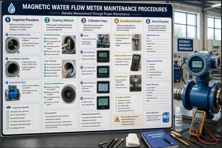
The main goal is simple: keep the meter accurate by controlling the problems that usually appear after installation—coating, corrosion, grounding faults, cable damage, vibration, poor records, and unverified calibration drift.

The purpose of this guide is to give a practical maintenance workflow for magnetic water flow meters. It focuses on field actions that protect long-term accuracy, not only factory specifications.
Magnetic flow meters are often described as “low maintenance” because they have no moving parts. That is partly true. There are no turbine blades, bearings, or gears to wear out.
But “no moving parts” does not mean “no maintenance.” Accuracy can still degrade when electrodes become coated, liners are damaged, grounding is poor, cables absorb moisture, or the pipe is not full.
Quick Glossary
- Magnetic flow meter: A flow meter that uses a magnetic field and electrode voltage to measure conductive liquid flow.
- Electrode: A metal contact inside the meter that detects the small voltage generated by flowing water.
- Liner: The protective inner surface of the meter body, often rubber, PTFE, or other chemical-resistant material.
- Grounding: The electrical reference connection that stabilizes the measurement signal.
- Calibration: Comparing the meter reading with a trusted reference to confirm accuracy.
- Verification: A check that confirms meter health without necessarily changing the calibration.
Readers will learn how to inspect, clean, verify, document, and troubleshoot magnetic water flow meters. The expected outcome is fewer unexplained readings, fewer emergency callouts, and stronger confidence in water balance, billing, dosing, and compliance data.
For broader selection guidance before installation, Jade Ant Instruments provides a detailed magnetic flow meter selection guide for water and chemical service. For liner, electrode, grounding, and sizing details, see the electromagnetic flow meter engineering guide.
Understanding Magnetic Water Flow Meters
How They Measure Flow
Magnetic water flow meters work by Faraday’s law of electromagnetic induction. In simple terms: when conductive water moves through a magnetic field, it creates a small voltage.
The meter measures that voltage with two electrodes. The voltage increases when flow velocity increases.
A simplified relationship is:
Signal voltage ≈ magnetic field × pipe diameter × water velocity
The transmitter converts this signal into a flow rate such as m³/h, L/min, GPM, or totalized volume.
.jpg "Magnetic Water Flow Meter with Conductive Liquid Flow")
Typical Operating Ranges and Limitations
Magnetic water flow meters are usually suitable for conductive liquids. They are not suitable for dry gas, steam, pure hydrocarbons, or very low-conductivity liquids unless the specific meter is designed for that condition.
Typical strengths include:
- No moving parts in the flow path
- Low pressure loss
- Good performance with many water and wastewater applications
- Bidirectional flow measurement on many models
- Useful diagnostics in modern transmitters
Typical limitations include:
- The pipe should remain full
- The liquid must be conductive enough
- Air bubbles can create unstable readings
- Electrode coating can reduce signal quality
- Grounding and shielding must be correct
- Wrong liner or electrode material can fail in aggressive water chemistry
Industry insight: in water and wastewater plants, many magnetic meter issues are not caused by meter electronics. They are caused by site conditions—partially filled pipes, poor earthing, damaged cables, sediment buildup, or chemical scaling.
Safety and Preparation
Lockout/Tagout and Electrical Safety
Lockout/tagout, often shortened to LOTO, means isolating energy sources before maintenance. For magnetic water flow meters, this may include electrical power, pump energy, pressure, and chemical feed systems.
Before work begins:
- Confirm the meter tag number and pipeline service
- Review the site safety procedure
- Isolate electrical power when opening transmitter covers
- Depressurize and drain the pipe if removing the sensor
- Confirm that chemical dosing or cleaning systems are isolated
- Use a calibrated voltage tester before touching terminals
For electrical safety symbols and protective earth identification, the IEC protective earth symbol is widely used in industrial wiring. See the IEC 60417 protective earth symbol reference.
Handling and Personal Protective Equipment (PPE)
PPE means personal protective equipment. It protects workers from pressure, chemicals, sharp edges, electrical hazards, and contamination.
Typical PPE may include:
- Safety glasses or face shield
- Chemical-resistant gloves
- Protective clothing
- Safety shoes
- Hearing protection near pumps
- Respiratory protection where chemical vapors or wastewater gases may exist
Do not lift large magnetic flow sensors by the transmitter housing. Use approved lifting points and protect the liner from impact.
System Isolation Steps
System isolation prevents water release, electrical shock, and false operation during maintenance.
A practical isolation sequence is:
- Notify operations and confirm maintenance window.
- Record the current flow reading and totalizer value.
- Stop or bypass flow if required.
- Close upstream and downstream isolation valves.
- Depressurize the section safely.
- Drain and flush if the water contains chemicals or sludge.
- Lock and tag all relevant energy sources.
- Confirm zero energy before opening covers or removing the meter.
Routine Inspection of Physical Condition
Visual Signs of Wear and Corrosion
Routine visual inspection should be simple and consistent. Look for changes that were not present during commissioning.
Check for:
- Rust on flanges, bolts, conduit entries, or transmitter brackets
- Paint blistering around the sensor body
- Water marks below cable glands
- Cracked display windows
- Damaged grounding straps
- Loose junction boxes
- Signs of liner swelling or chemical attack during internal inspection
In wastewater and coastal installations, corrosion can spread quickly. A small cable gland leak can become a signal failure when moisture reaches terminals or the remote transmitter cable.
Connector and Cable Checks
Signal cables carry very small measurement signals. Poor cable condition can create drift, spikes, or intermittent readings.
Inspect:
- Cable glands for tightness and water ingress
- Shield termination and grounding points
- Conduit seals and drain points
- Cracked insulation
- Loose terminals
- Incorrect cable routing near power cables or variable-frequency drives
For remote-type magnetic meters, keep sensor cables separated from high-power motor cables. If they must cross, cross at 90 degrees rather than running in parallel.
Sensor Housing Integrity
The sensor housing protects coils, electrodes, and internal wiring. Damage to the housing can affect both safety and accuracy.
Check that the housing is sealed, mechanically supported, and not carrying pipe stress. Pipe stress can distort flanges, damage gaskets, and eventually affect liner or electrode sealing.

Cleaning and Descaling
When to Clean and Indicators of Buildup
Cleaning is needed when deposits interfere with electrode contact or reduce the effective pipe area.
Common buildup sources include:
- Iron and manganese deposits
- Calcium carbonate scale
- Biofilm
- Wastewater grease
- Chemical precipitates
- Sludge and sediment
Signs that cleaning may be needed:
- Slow drift compared with a reference reading
- Unstable zero reading when the pipe is full and flow is stopped
- Increasing electrode impedance alarms
- Noise spikes during steady pump operation
- Different readings after flushing or flow reversal
Cleaning Methods and Appropriate Solvents
Cleaning method depends on the liner, electrode material, water chemistry, and deposit type. Always check the meter manual before using chemicals.
| Deposit Type | Possible Cleaning Method | Precautions | Record in Maintenance Log |
|---|---|---|---|
| Soft sediment | Flush with clean water | Avoid high-pressure jets directly on electrodes unless approved | Flush time, flow direction, before/after reading |
| Biofilm | Approved disinfectant or mild cleaning solution | Confirm liner and electrode compatibility | Chemical used, concentration, contact time |
| Mineral scale | Mild acid cleaning if compatible | Protect stainless steel, rubber, PTFE, and seals as specified | pH, duration, neutralization method |
| Grease or oil film | Approved detergent or solvent | Do not use solvents that swell liners or seals | Solvent name, rinse result, visual condition |
| Hard deposits | Manual cleaning with soft tools | Do not scratch electrodes or liner | Photos, deposit location, electrode condition |
Fluid Quality Considerations
Contaminants and Their Effects on Measurement Accuracy
Water quality directly affects magnetic meter performance. The meter does not only “see” water velocity. It also depends on stable electrical contact between the conductive liquid and electrodes.
Contaminants can create several problems:
- Air bubbles: Cause noisy or low readings because gas is not conductive.
- Sand and grit: Can erode liners and electrodes over time.
- Iron deposits: Can coat electrodes and shift the signal.
- Grease: Can form insulating films on electrodes.
- Chemical precipitates: Can build scale after pH or temperature changes.
- Low conductivity: Can weaken the measurement signal.
Industry insight: in reclaimed water and wastewater reuse systems, chemistry changes can be more important than flow range. A meter that was stable in raw water can drift after coagulant, chlorine, lime, or polymer dosing changes upstream.
Filtration and Impact on Sample Lines
Mainline magnetic meters usually do not require fine filtration. However, heavy solids, rags, or large debris can damage liners or create unstable flow profiles.
If the system includes a bypass or sample line, filtration may be needed to protect small valves and reference meters. Keep sample lines clean, short, and representative of the main process.
For wastewater applications, the Jade Ant Instruments article on magnetic versus ultrasonic flow meters for wastewater explains how solids, pipe filling, and maintenance access influence technology choice.
Calibration and Verification
Recommended Calibration Frequency
Calibration confirms the meter reading against a trusted reference. Verification checks meter health and signal condition, often without removing the meter.
Recommended frequency depends on risk:
- Clean utility water: Verify every 6–12 months; calibrate every 2–3 years if stable.
- Billing or custody-related water: Follow regulatory or contract requirements.
- Chemical dosing water: Verify more often because small errors affect chemical cost.
- Wastewater or scaling service: Inspect and verify more frequently, often every 3–6 months.
- After major maintenance: Verify immediately after sensor removal, cable replacement, transmitter replacement, or pipe work.
Jade Ant Instruments provides a step-by-step resource on magnetic flow meter calibration practical tips. For wider calibration planning, see the flow meter sensor calibration setup guide.
Verification Methods: Standard Flow, Cross-Checks
Verification can be done several ways. The right method depends on pipe size, shutdown access, required uncertainty, and whether a reference meter is available.
| Verification Method | Best Use Case | Strength | Limitation |
|---|---|---|---|
| Built-in meter verification | Modern transmitters with diagnostics | Fast and non-invasive | Does not always prove real flow accuracy |
| Clamp-on ultrasonic cross-check | Large water pipes where removal is difficult | No pipe cutting required | Needs correct pipe data and good acoustic coupling |
| Tank drawdown or fill test | Water storage and batch systems | Practical and understandable | Requires stable level measurement and timing |
| Reference meter in series | Calibration bench or bypass loop | Strong comparison method | Requires calibrated reference and stable flow |
| Mass balance | Process units with multiple meters | Useful for system-level review | Can hide individual meter errors |
For general calibration practice, Fluke’s flowmeter calibration best practices emphasize traceability, stable conditions, and matching calibration conditions to field operation.
Recommended Verification Frequency by Service
Qualitative schedule; adjust for regulation, risk, and historical drift
0
3
6
9
12
15
Clean water
Wastewater
Scaling water
Billing water
Months between verification
Electrical and Signal Integrity
Wiring and Connector Checks
Magnetic flow meters produce small electrode signals. Wiring problems can look like process problems.
Check the following during planned maintenance:
- Terminal tightness
- Moisture inside transmitter covers
- Correct cable type for remote sensors
- Shield continuity
- Proper separation from power cables
- Stable power supply voltage
- No loose conduit or cable gland damage
If a signal is intermittent, gently inspect cable movement near glands and junction boxes. A cable fault may only appear during vibration or temperature change.
EMI, Grounding, and Shielding Considerations
EMI means electromagnetic interference. It is unwanted electrical noise from motors, variable-frequency drives, radio systems, welding machines, or power cables.
Grounding gives the meter a stable electrical reference. Without correct grounding, the transmitter may read unstable flow even when actual water flow is steady.
Use:
- Grounding rings or grounding electrodes where required
- Correct protective earth connection
- Shielded signal cables
- Single-point shield termination when specified
- Separate routing from motor power cables
- Surge protection in lightning-prone or remote installations
Emerson’s article on magnetic flow meter setup and maintenance tips provides useful field reminders about grounding and installation.

Installation and Environment
Piping Geometry and Installation Best Practices
Good maintenance starts with good installation. Even a well-maintained meter will perform poorly if it is installed in the wrong hydraulic condition.
Best practices include:
- Install where the pipe stays full
- Avoid high points where air collects
- Follow straight-run guidance from the manufacturer
- Keep valves, elbows, and pumps away from the meter when possible
- Support the pipe so the meter does not carry mechanical stress
- Use correct gaskets that do not protrude into the flow path
- Install grounding rings when required by pipe material and meter design
For technology selection across water and other industrial services, Jade Ant Instruments also provides a broader flowmeter sensor selection factors guide.
Temperature, Pressure, and Vibration Effects
Magnetic water flow meters are affected by their environment. Temperature can age seals and cable insulation. Pressure cycles can stress gaskets and liners. Vibration can loosen terminals and damage supports.
Monitor:
- Ambient temperature inside outdoor enclosures
- Pipe vibration near pumps
- Pressure surges and water hammer
- Sun exposure on transmitter displays
- Flooding risk in underground chambers
- Condensation inside junction boxes
Magnetic Water Flow Meter Installation Check Points
Flow direction
Magmeter
Sensor body
Transmitter
Grounding ring
Grounding ring
Avoid air pockets
Control vibration and pipe stress
Maintenance checks should include pipe filling, grounding, cable routing, gasket condition, support, and transmitter environment.
Maintenance Records and Documentation
Logging Maintenance Activities and Readings
Good records turn maintenance from guesswork into trend analysis. Record both what was done and what changed afterward.
The following Excel-ready table can be copied into a maintenance spreadsheet.
| Date | Meter Tag | Service | Flow Reading Before | Flow Reading After | Totalizer | Action Taken | Observed Condition | Technician | Next Review Date |
|---|---|---|---|---|---|---|---|---|---|
| 2026-05-03 | FIT-204 | Filtered water | 118.6 m³/h | 119.1 m³/h | 2,486,220 m³ | Zero check, terminal inspection | No moisture; ground strap tight | J. Smith | 2026-11-03 |
| 2026-05-03 | FIT-311 | Wastewater return | Unstable | Stable at 42.3 m³/h | 917,530 m³ | Cleaned electrodes and flushed line | Biofilm and grit found | A. Lee | 2026-08-03 |
Change Management and Version Control
Many flow measurement issues start after a configuration change that was not recorded.
Record changes to:
- Meter size setting
- Flow range
- Low-flow cutoff
- Damping time
- Pulse output scaling
- Analog output range
- Firmware version
- Communication address
- Calibration factor
Save a configuration backup after commissioning and after every approved change. If the meter reading changes later, the team can compare the current setup with the known-good baseline.
Common Maintenance Issue Sources
Qualitative field model for magnetic water flow meters
Issue
Sources
Electrode coating: 20%
Grounding / EMI: 25%
Cable and moisture: 20%
Pipe filling / air: 20%
Configuration changes: 15%
Troubleshooting and Common Issues
Diagnosing Unstable Readings
Unstable readings can come from the process or from the measurement system. Start with the simple checks first.
Common causes include:
- Air bubbles or partially filled pipe
- Pump cavitation
- Loose grounding connection
- Electrode coating
- Moisture in cable glands or junction boxes
- Signal cable routed near high-power cables
- Incorrect damping or low-flow cutoff setting
A practical troubleshooting sequence:
- Check whether the process flow is truly stable.
- Confirm the pipe is full.
- Check for air release or cavitation symptoms.
- Inspect grounding and shield connections.
- Look for transmitter diagnostic alarms.
- Check electrode condition if process history suggests coating.
- Compare with tank level, pump curve, or temporary reference meter.
No Signal or Intermittent Signal Scenarios
No signal usually points to power, wiring, sensor coil, transmitter, or severe process condition issues.
Check:
- Power supply voltage
- Fuse or breaker status
- Transmitter display and diagnostic code
- Remote sensor cable continuity
- Coil resistance if specified by the manufacturer
- Terminal moisture or corrosion
- Output loop continuity for 4–20 mA systems
- PLC or SCADA scaling and channel status
Recommended YouTube Video
The following video gives a practical overview of magnetic flow meter calibration. It is useful for technicians who want a visual reference before planning verification work.
A structured maintenance program is essential for keeping magnetic water flow meters accurate over the long term. The meter may have no moving parts, but it still depends on clean electrodes, correct grounding, stable wiring, full-pipe flow, suitable water chemistry, and verified configuration.
Use this quick-reference checklist for ongoing practice:
- Inspect housing, flanges, cable glands, and grounding straps.
- Check transmitter alarms and diagnostic values.
- Confirm the pipe is full and free from air-pocket issues.
- Review water quality changes that may cause coating or scale.
- Clean electrodes and liner only with approved methods.
- Verify readings with a reference method on a defined schedule.
- Record as-found and as-left readings after maintenance.
- Track configuration changes with version control.
- Review trend data periodically instead of waiting for failures.
Proactive logging is especially valuable. A trend of rising noise, increasing zero offset, or repeated moisture findings can reveal problems before the meter fails. In water utilities, that early warning can protect billing accuracy, chemical dosing, pump optimization, and compliance reporting.
When maintenance history shows repeated drift or unstable readings, do not only replace parts. Review the full measurement loop: pipe condition, water quality, grounding, cable routing, transmitter settings, and reference verification method.
FAQs
How often should a magnetic flow meter be recalibrated?
For clean water service, many sites verify every 6–12 months and recalibrate every 2–3 years if the meter remains stable. Harsh wastewater, billing, chemical dosing, or regulatory applications may require shorter intervals based on risk and site rules.
What cleaning agents are safe for sensor housings?
Safe cleaning agents depend on the liner, electrode, gasket, and housing materials. Mild detergent and clean water are often acceptable for external cleaning. Chemical descaling or solvent cleaning should only be done after confirming compatibility with the manufacturer’s material chart.
How do I diagnose a sudden drift in readings?
First confirm the process has not changed. Then check pipe filling, air bubbles, grounding, cable moisture, electrode coating, transmitter diagnostics, and recent configuration changes. Cross-check with tank level, pump curve, or a temporary reference meter if possible.
Can a magnetic water flow meter work in a partially full pipe?
Standard magnetic flow meters need a full pipe for accurate measurement. A partially full pipe can cause unstable or biased readings because the meter assumes the full cross-section is carrying conductive liquid.
Why does grounding affect magnetic flow meter accuracy?
The electrode signal is very small. Poor grounding allows electrical noise and unstable reference voltage to enter the measurement. This can create drift, spikes, or unstable readings even when real flow is steady.
What are the most common causes of unstable magnetic meter readings?
Common causes include air bubbles, partially filled pipe, poor grounding, electrode coating, cable moisture, EMI from nearby power equipment, vibration, and incorrect transmitter damping or scaling settings.
Should I clean electrodes on a fixed schedule?
Clean based on service condition and evidence of buildup. Wastewater, scaling water, or chemically treated water may need scheduled cleaning. Clean water systems may only need inspection and verification unless diagnostics show coating or signal instability.
Can I verify a magnetic flow meter without removing it?
Yes. Options include built-in verification diagnostics, clamp-on ultrasonic cross-checks, tank fill or drawdown tests, and process mass balance. The best method depends on required accuracy and site access.