
Define the purpose of flow meters in industrial heat transfer systems
In an industrial heat transfer fluid system, the flow meter is not simply a device for displaying flow rate. It helps protect heaters, verify heat exchanger duty, calculate energy transfer, detect pump performance loss, and identify early signs of fouling or blockage. When thermal oil, glycol, silicone oil, or synthetic heat transfer fluid circulates through a production line, flow stability directly affects process temperature control and product consistency.
A reliable heat transfer fluid flow meter also gives operators a way to confirm that the actual circulation rate matches the design basis. Without that data, a plant may continue operating with partially closed valves, dirty strainers, aging pumps, or degraded fluid while the temperature controller compensates quietly in the background.
Brief overview of common flow meter technologies used for heat transfer fluids
Common technologies include ultrasonic, Coriolis, electromagnetic, turbine, vortex, and positive displacement flow meters. Each technology behaves differently when exposed to high temperature, changing viscosity, limited straight pipe run, suspended degradation products, vibration, or non-conductive thermal oils.
For example, Coriolis meters are often selected when mass flow and density are important, while ultrasonic meters are attractive for large lines or retrofit installations where pressure drop must be minimized. Electromagnetic meters can be excellent for conductive liquids such as water-glycol mixtures but are generally unsuitable for most non-conductive thermal oils.
Outline of what readers will learn about selection and installation
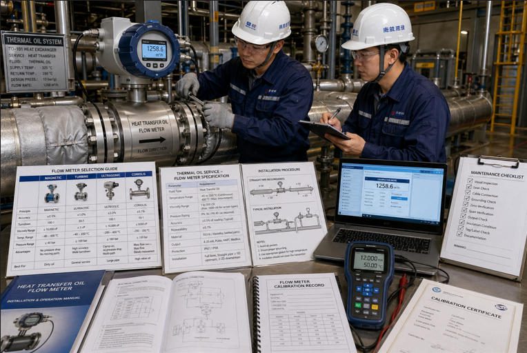
This article explains how to define process requirements, compare flow meter technologies, specify measurement range and output signals, check materials and thermal limits, install the meter correctly, commission the system, and plan long-term calibration and maintenance. It also includes an Excel-style comparison table, a bar chart, a pie chart, field images, and a YouTube video on straight-run concepts.
Understanding the role of flow meters in heat transfer systems
Why accurate flow measurement matters for process performance
Heat transfer performance is commonly evaluated using mass flow rate, fluid heat capacity, density, and temperature difference. If the measured flow rate is wrong, the calculated heat duty is wrong as well. A 2% flow error in a high-load thermal oil loop can distort energy-balance calculations enough to mislead troubleshooting decisions.
In many plants, the temperature controller hides hydraulic problems for a long time. The heater fires harder, the valve opens further, or the pump speed increases, but the root cause may be lower actual flow through the process. A properly selected flow meter allows the maintenance team to separate control behavior from hydraulic reality.
Key performance indicators: kW, affected by flow measurement
Flow measurement influences several important operating indicators:
- Heat duty in kW: calculated from mass flow, heat capacity, and temperature difference.
- Heater safety margin: low flow can increase film temperature and accelerate thermal fluid degradation.
- Heat exchanger performance: stable flow data helps distinguish fouling from reduced circulation.
- Pump performance: flow rate combined with differential pressure and motor power gives a clearer view of pump efficiency.
- Batch repeatability: consistent flow improves heating and cooling profiles across production batches.

Types of flow meters suitable for heat transfer fluids
Ultrasonic, Coriolis, Electromagnetic, Turbine/Positive Displacement
The most common flow meter options for heat transfer fluid service include:
- Ultrasonic flow meters: Useful for large pipes, retrofit work, and low pressure-drop applications. Clamp-on designs can be installed without cutting the pipe, but performance depends on pipe condition, acoustic coupling, fluid sound velocity, and entrained gas.
- Coriolis flow meters: Provide direct mass flow measurement and often density output. They are strong candidates when energy balance, batch repeatability, or high accuracy is required.
- Electromagnetic flow meters: Suitable for conductive liquids such as water-glycol mixtures. They are generally not suitable for most non-conductive thermal oils.
- Turbine flow meters: Compact and responsive, but sensitive to viscosity, bearing wear, contamination, and flow profile disturbance.
- Positive displacement flow meters: Useful for viscous fluids and lower flow rates. They require attention to pressure drop, filtration, and moving-part maintenance.
Pros and cons for each technology with HTF considerations
| Meter Type | Best Fit in HTF Service | Advantages | Limitations | HTF Specification Watchpoints |
|---|---|---|---|---|
| Ultrasonic | Large thermal oil lines, retrofit projects, low pressure-drop systems | No obstruction, clamp-on option, good for energy surveys | Needs good acoustic coupling; bubbles and pipe deposits can affect readings | Pipe material, wall thickness, acoustic velocity, temperature-rated transducers |
| Coriolis | High-accuracy mass flow, density monitoring, batch heating systems | Direct mass flow, density output, lower dependence on flow profile | Higher cost, pressure drop, heavy body on large pipe sizes | Temperature rating, pressure drop, vibration isolation, zero verification |
| Electromagnetic | Water-glycol or conductive HTF loops | No moving parts, low pressure drop, stable for conductive liquids | Not suitable for most non-conductive thermal oils | Minimum conductivity, liner temperature limit, grounding rings |
| Turbine | Clean fluids with stable viscosity and good filtration | Fast response, compact size, relatively economical | Moving parts; viscosity and bearing wear affect accuracy | Strainers, bearings, viscosity compensation, straight-run piping |
| Positive Displacement | Viscous HTFs, lower flow rates, dosing or batching | Good low-flow resolution; handles higher viscosity | Pressure drop, moving parts, contamination sensitivity | Bypass protection, filtration, differential pressure, thermal expansion clearance |
For broader meter-selection principles, see the
industrial flow meter selection guide from Jade Ant Instruments.
For a general engineering comparison, the
OMEGA flowmeter selection reference is also useful.
Defining process requirements and constraints
Fluid properties: viscosity, density, temperature range
Heat transfer fluids change significantly with temperature. A thermal oil that flows easily at 250°C may become highly viscous during cold startup. Density also changes with temperature, which affects volumetric flow calculations. For this reason, engineers should request full property curves from the fluid supplier rather than relying on a single viscosity or density value.
Supplier documents such as the
Therminol heat transfer fluids selection guide
show the level of temperature-property detail that should be considered during specification.
System pressure, piping layout, and accessibility
The flow meter pressure rating must cover normal operation, startup, shutdown, pump deadhead scenarios, and blocked-in thermal expansion conditions. Piping layout determines whether straight-run requirements can be met, while physical access determines whether technicians can safely inspect, calibrate, and service the device.
Desired accuracy, turndown ratio, and response time
Accuracy should be reviewed across the actual operating range, not only at maximum flow. Turndown ratio is especially important in batch plants, variable-speed pump loops, seasonal heating systems, and pilot units. Response time matters when the flow signal is used for heater permissives, alarms, or emergency shutdown logic.
Selecting measurement range, accuracy, and output signals
Sizing the meter range to maintain accuracy across load conditions
Size the meter around normal operating flow, minimum controllable flow, startup flow, and maximum design flow. Oversized meters often operate too close to the low end of their calibrated range, where uncertainty increases. Undersized meters may create excess pressure drop, noise, cavitation risk, or velocity-related wear.
Required output formats: 4-20 mA, pulse, digital, HART/Fieldbus
Most industrial systems use 4-20 mA for continuous flow, pulse output for totalization, and HART, Modbus, Profibus, Foundation Fieldbus, or Ethernet-based protocols for diagnostics. If density, temperature, or meter health data is valuable, confirm that the PLC, DCS, or historian can read and store those extra variables.
Materials, wetted parts, and chemical compatibility for HTFs
Corrosion resistance, material compatibility charts
Common wetted materials include stainless steel, carbon steel, high-temperature elastomers, graphite seals, and specialized liners. Compatibility must be checked against the base fluid, oxidation byproducts, cleaning agents, and additives. A material that works with fresh HTF may not perform the same after years of thermal aging and contamination.
Thermal expansion, sealing, and containment considerations
Thermal expansion can change flange loading, stress pipe connections, and affect clearances inside mechanical meters. Gasket material, bolt torque, insulation cutouts, and post-heat-up leak checks should be part of the installation plan. For thermal oil systems, containment is also a safety issue because leaking hot oil can create fire and burn hazards.
Temperature management and insulation considerations
Temperature limits of the meter and electronics
Always verify separate temperature ratings for the sensor body, transmitter, display, cable, seals, and junction box. A sensor may tolerate high process temperature while the transmitter electronics require remote mounting. Insulation should not trap heat around electronics unless the manufacturer explicitly allows it.
Effects of HTF temperature on measurement accuracy
Temperature affects viscosity, density, sound velocity, Reynolds number, and mechanical clearances. Ultrasonic meters are influenced by acoustic velocity and coupling quality. Turbine and positive displacement meters are affected by viscosity and wear. Coriolis meters require proper temperature compensation and zero verification.

Installation best practices and flow conditioning
Piping alignment, straight-run requirements, and valves placement
Flow meters perform best with a stable velocity profile. Avoid installing the meter immediately after pumps, elbows, partially open valves, reducers, or tees unless the manufacturer’s installation manual allows it. Where possible, control valves should be placed downstream of the meter to reduce upstream turbulence.
The International Society of Automation provides practical discussion on
selecting and sizing flowmeters,
including why installation conditions matter as much as the nameplate accuracy.
Flow conditioning, filtration, and purge provisions
Flow conditioners can help when straight run is limited, but they add pressure drop and must be reviewed for fouling risk. Turbine and positive displacement meters typically need strainers. Purge, drain, and vent provisions are useful for removing trapped air, startup debris, degraded fluid, and maintenance residues.
Video: straight-run concepts are important for many industrial flow meter installations. Always follow the specific meter manufacturer’s manual for final upstream and downstream pipe-run requirements.
Installation of electrical and communication interfaces
Electrical grounding, cable routing, and safety
Use shielded instrument cable where required, separate signal cables from power wiring, and follow grounding instructions carefully. Grounding is especially important for electromagnetic meters and for any transmitter installed near large motors, variable-frequency drives, or heating equipment. Cable insulation must be rated for the local ambient temperature around hot pipework.
Protocols, compatibility with plant networks, and EMC
Confirm communication compatibility before purchase. A meter with useful diagnostics will not deliver full value if the control system only reads one analog signal. HART, Modbus, Profibus, Foundation Fieldbus, EtherNet/IP, and pulse outputs require different wiring, configuration, and maintenance practices. Electromagnetic compatibility should be reviewed when the meter is installed near drives, motors, induction heaters, or welding equipment.
Calibration, validation, and maintenance planning
Factory calibration vs. field verification
Factory calibration establishes traceability under controlled conditions. Field verification confirms that installation, configuration, process conditions, and wiring have not compromised the measurement. Jade Ant Instruments recommends treating calibration documents, configuration records, and commissioning screenshots as part of the turnover package rather than leaving them as separate files.
Recalibration intervals and uptime considerations
Recalibration intervals depend on process criticality, temperature severity, fluid cleanliness, operating hours, and site quality procedures. A meter used for heater protection may require more frequent verification than a meter used only for non-critical energy monitoring. If shutdowns are expensive, specify in-situ verification or removable sensor options where practical.
Diagnostics and role of diagnostics in reliability
Modern meters can detect signal loss, coating, density shift, tube imbalance, electronics temperature, empty pipe conditions, or excessive noise depending on the technology. For more detail on verification workflow, see this
flow meter sensor calibration setup guide.
Safety, compliance, and risk management
ATEX/IECEx and other regional certifications for hazardous areas
If the flow meter is installed in a classified area, the sensor, transmitter, cable glands, junction boxes, and barriers must match the hazardous-area classification. Review ATEX, IECEx, NEC, UKEX, or local requirements as applicable. Useful references include the
IECEx certification system
and the European Commission’s
ATEX equipment guidance.
Lockout/Tagout and installation safety practices
HTF piping can remain dangerously hot after shutdown, and blocked-in fluid can pressurize as it heats. Installation work should include isolation, depressurization, draining, cooling, ventilation, spill containment, and verification before line breaking. For U.S. facilities, OSHA’s
control of hazardous energy guidance
is a relevant starting point for lockout/tagout planning.
Commissioning, startup, and performance verification
Pre-commissioning checks and leak tests
Pre-commissioning should confirm meter orientation, flow direction, gasket type, bolt torque, transmitter tag numbers, cable routing, grounding, configuration, and insulation clearance. Leak checks should be performed at ambient conditions and again after controlled heat-up because thermal expansion can change flange loading.
Functional testing and commissioning acceptance criteria
Acceptance criteria should define expected flow range, signal scaling, totalizer units, alarm setpoints, interlock response, diagnostic status, and comparison against a pump curve or temporary reference measurement. A good commissioning record includes exported configuration files or screenshots so the final installed settings are traceable.
Troubleshooting common issues and optimization tips
Common causes of drift, blockage, or signal loss
- Drift: viscosity changes, coating, zero shift, bearing wear, transmitter heat stress, or incorrect density compensation.
- Blockage: degraded HTF sludge, gasket fragments, filter bypass, startup debris, or carbonized fluid deposits.
- Signal loss: poor grounding, damaged cable, empty pipe, bubbles, poor ultrasonic coupling, or EMC interference.
Tuning for temperature-driven flow changes in HTFs
During cold startup, HTF viscosity may be much higher than at operating temperature. Operators should avoid judging pump or meter performance from cold-flow readings alone. Trend flow against temperature, pump speed, differential pressure, and valve position. Where justified, use temperature or density compensation to improve energy calculations.
Lifecycle cost and total ownership considerations
Acquisition cost, installation, and maintenance costs
The lowest purchase price is not always the lowest installed cost. A meter that requires pipe modification, long shutdown time, heat tracing changes, or frequent cleaning may cost more over five years than a higher-priced technology with lower maintenance demand. Compare cost as installed, commissioned, verified, and maintained.
Spare parts, service intervals, and support
Spare parts may include gaskets, seals, electronics modules, display covers, ultrasonic transducers, bearings, or replacement sensors depending on technology. For critical loops, confirm documentation support, calibration records, replacement lead time, and local service capability. Engineers comparing options can also review
five practical flow meter selection factors
before issuing a purchase specification.
Documentation, training, and handover
As-built drawings, device IDs, and calibration certificates
Handover documents should include datasheets, calibration certificates, material certificates where required, hazardous-area certificates, wiring drawings, device IDs, loop diagrams, instrument index updates, and final configuration records. These documents reduce troubleshooting time when staff changes or when the plant expands.
Operator and maintenance staff training
Training should cover normal readings, startup behavior, alarm meaning, diagnostic messages, cleaning or verification procedures, and protected transmitter parameters. Operators should understand the difference between a true low-flow process condition and a measurement diagnostic warning.

Emerging trends and future-proofing
Smart meters, data analytics, and predictive maintenance
Smart meters increasingly provide diagnostic variables that help identify coating, entrained gas, electronics overheating, vibration, and process instability. When these diagnostics are trended in a historian, maintenance teams can move from fixed calendar inspections toward condition-based verification.
Hybrid solutions and multi-parameter sensing
Hybrid measurement strategies combine flow, temperature, pressure, density, and energy calculations. In HTF systems, this supports better heater efficiency monitoring and faster identification of fouled heat exchangers. Multi-parameter data is especially useful when flow changes are caused by both viscosity and mechanical restrictions.
Industry 4.0 readiness for HTF systems
Industry 4.0 readiness means more than adding a digital protocol. It requires reliable tag naming, cybersecurity review, diagnostic interpretation, historian integration, and maintenance workflows. For new installations, specify not only the meter accuracy but also the data required for long-term reliability and energy analysis.
Summarize key decision criteria for selecting a flow meter for HTFs
Select a heat transfer fluid flow meter by starting with the process: fluid type, viscosity curve, density, temperature, pressure, pipe size, accuracy target, turndown, pressure-drop allowance, hazardous-area classification, and maintenance access. Only then should the technology shortlist be finalized.
Highlight installation and maintenance best practices to ensure reliability
Reliable measurement depends on correct sizing, straight-run planning, grounding, insulation strategy, filtration, controlled startup, documented configuration, and periodic verification. Calibration and diagnostics should be designed into the maintenance program from the beginning.
Encourage a structured procurement and commissioning approach
A structured specification prevents expensive rework. For projects involving thermal oil, glycol, or other heat transfer fluids,
Jade Ant Instruments flow meter solutions
can support review of operating conditions, meter technology options, and output signal requirements before procurement.
FAQs
What factors most affect flow meter accuracy in heat transfer fluids?
The main factors are viscosity, density, temperature, flow profile, entrained gas, pipe condition, vibration, installation straight run, meter sizing, and calibration condition. In HTF systems, temperature-driven viscosity change is often underestimated.
How do HTF properties influence meter selection?
Conductivity determines whether an electromagnetic meter can be used. Viscosity affects turbine, positive displacement, and Reynolds-number-dependent technologies. Density affects volumetric-to-mass conversion. Acoustic properties affect ultrasonic measurement, while temperature limits influence seals, electronics, cables, and transmitter mounting.
What are the typical commissioning steps for HTF flow meters?
Typical steps include installation inspection, wiring and grounding checks, transmitter configuration, loop check, leak test, controlled heat-up, air removal, zero or baseline verification, comparison against process expectations, alarm testing, totalizer confirmation, and final documentation.
How often should flow meters be recalibrated in industrial HTF systems?
Recalibration intervals depend on criticality, safety function, operating temperature, fluid cleanliness, meter type, and site quality procedures. Many plants begin with annual verification and adjust the interval based on drift history and risk level.
What safety certifications are commonly required for HTF meters in hazardous areas?
Common certifications include ATEX, IECEx, NEC/CEC approvals, UKEX, and regional hazardous-area approvals. The required certificate depends on area classification, gas or vapor group, temperature class, protection method, and local regulations.
Can clamp-on ultrasonic meters measure thermal oil?
Yes, in many cases. Success depends on pipe material, wall thickness, pipe condition, temperature, acoustic coupling, fluid sound velocity, and the absence of excessive bubbles or deposits. High-temperature transducers and correct mounting hardware are essential.
Why is straight pipe run important for flow meters?
Elbows, pumps, valves, reducers, and tees disturb the velocity profile. Many meters assume a stable profile to calculate flow accurately. Straight pipe run or flow conditioning reduces swirl and asymmetry before the fluid enters the meter.
Which flow meter is best for high-temperature thermal oil?
There is no universal best choice. Coriolis meters are strong for high-accuracy mass flow, ultrasonic meters are attractive for large low-pressure-drop lines, and positive displacement meters can work well for viscous lower-flow service. The correct answer depends on temperature, viscosity, pipe size, accuracy, pressure drop, and maintenance strategy.