
In 2024, a 200 MLD municipal water plant in Guangdong Province replaced fourteen oversized turbine flow meters with correctly sized electromagnetic units. Within 90 days, chemical-dosing accuracy improved by 11 %, and the plant saved roughly USD 48,000 per year in coagulant costs alone. The meters themselves were not exotic; the improvement came entirely from applying a disciplined selection process.
That process boils down to five factors: performance requirements, fluid properties, installation constraints, environmental conditions, and total cost of ownership (TCO). Skip any one and the result is predictable — noisy readings, premature sensor failure, or a measurement that looks “accurate in the lab” but drifts in the plant. According to Global Market Insights, the electromagnetic segment alone held 28.5 % of the USD 11.44 billion global flow-meter market in 2025, yet industry surveys consistently show that more than half of field complaints trace back to selection or installation errors — not sensor defects.
This guide turns the classic five-factor logic into a field-ready workflow you can use for water, wastewater, steam, gas, chemicals, and general process industries. We reference real sizing calculations, pressure-loss economics, material-compatibility tables, and a downloadable Excel TCO comparison. Throughout the article, we highlight practical resources from Jade Ant Instruments, a China-based ISO-certified manufacturer whose product range spans electromagnetic, ultrasonic, vortex, turbine, and Coriolis meters.
“Flow measurement problems are rarely caused by the sensor alone. In most troubleshooting cases, the root cause is a mismatch between meter technology, fluid behavior, and installation conditions — especially upstream disturbances and two-phase flow.”
— Senior Flow Measurement Specialist, Process Instrumentation
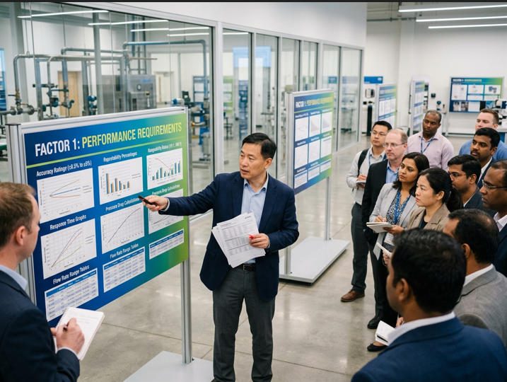
Factor 1: Performance Requirements — What the Meter Must Actually Deliver

1.1 Rate vs. Total vs. Both
Before comparing datasheets, answer one question: What is this measurement used for? If the signal drives a PID loop — valve position, VFD pump speed, chemical dosing — you need a stable, fast rate (instantaneous flow) output with strong repeatability. If the signal feeds a batch counter, billing system, or inventory reconciliation, you need traceable totalized (cumulative) volume or mass with proven linearity across the full range.
Positive-displacement and turbine flow meters generate pulses tied directly to swept volume, making totalizing inherently accurate for clean liquids. Electromagnetic flow meters and ultrasonic flow meters infer flow from velocity and excel at fast response for control — yet they can also totalize when paired with an integrator. The key is to align the meter’s “native signal behavior” with your objective so you avoid unnecessary complexity and error stacking.
1.2 Accuracy vs. Repeatability vs. Linearity
Many buyers overpay for nameplate accuracy when repeatability is the actual control driver. In a closed-loop system, a meter that repeats within ±0.05 % but carries a ±0.5 % bias may still control reliably — the controller reacts to changes, not absolute values. Conversely, a meter with strong lab accuracy but ±0.3 % repeatability in the field can cause valve hunting, false alarms, and product-quality variation.
Also consider the system-level error budget. If valve hysteresis is already ~2 %, buying a 0.2 % meter does not automatically improve the real-world process outcome. In those situations, invest in proper installation, signal integrity, and maintenance planning rather than chasing an extra decimal point on the spec sheet.
1.3 Flow Range and Turndown
A common mistake is sizing by pipe diameter alone. A DN150 electromagnetic meter on a line that normally runs at 0.15 m/s (well below the recommended 1–10 m/s window) will produce noisy, unreliable readings. The correct approach uses three inputs: your operating flow range (Qmin, Qnormal, Qmax), the meter’s rated upper and lower limits, and the required turndown ratio (Qmax ÷ Qmin). For a wastewater plant that peaks at 800 m³/h during storm events but idles at 40 m³/h overnight, you need a turndown of at least 20:1 — eliminating most mechanical meters from the shortlist.
1.4 Pressure Loss — The Hidden Energy Bill
Anything inserted into the flow stream creates non-recoverable pressure loss that the pump must compensate for — continuously. A standard orifice plate on a DN200 water line running 500 m³/h can impose 0.4–0.8 bar of permanent loss, costing roughly USD 2,800–5,600 per year in additional pumping energy (at USD 0.10/kWh). Over a 10-year lifecycle, that energy bill dwarfs the purchase price of a full-bore electromagnetic meter with near-zero loss. This is why the Jade Ant Instruments flow meter selection guide flags pressure-drop economics as a first-pass filter, not an afterthought.
1.5 Output Signal and Response Time
Define how the signal integrates with your control architecture: 4–20 mA for analog control stability and noise immunity over long cable runs; pulse/frequency for high-resolution totalizing; HART, Modbus, or PROFINET for diagnostics, density compensation, and asset-health data. Response time matters in unsteady flow — a meter feeding a fast dosing loop needs sub-second updates, whereas a daily billing totalizer can tolerate heavier filtering.
Video: “Flow Meters Explained — How to Choose the Right One” (Blue-White Industries, 2026).
Factor 2: Fluid Properties — What the Process Fluid “Does” to Your Meter
2.1 Temperature and Pressure
Before shortlisting technologies, define the fluid’s operating temperature and pressure — including startup transients, CIP cycles, and abnormal excursions. A PTFE-lined electromagnetic meter rated to 150 °C will survive a 180 °C steam-sterilization cycle only once before the liner delaminates. For gases, pressure and temperature shift density dramatically; ignoring compensation can introduce systematic 3–8 % errors that never self-correct.
2.2 Viscosity — The Silent Killer for Moving Parts
Viscosity is one of the most practical discriminators between meter types. High viscosity increases drag on turbine rotors, reduces rangeability on vortex meters, and can shift the Reynolds-number regime enough to invalidate published accuracy curves. In a Midwest soybean-oil plant, switching from a turbine meter (rated ±0.5 % on water) to a Coriolis mass flow meter reduced batch-weight variance from ±1.8 % to ±0.15 % — because Coriolis measurement is largely independent of viscosity.
2.3 Conductivity, Corrosion, and Fouling
Electromagnetic meters require a minimum fluid conductivity of approximately 5 μS/cm. Demineralized water (0.1 μS/cm) falls below this threshold, ruling out mag meters entirely. Corrosive fluids demand careful electrode and liner selection (see the magnetic flow meter material selection guide). Scaling and coating can drift electrode signals by 2–5 % within months if anti-fouling measures are not planned.
2.4 Two-Phase and Slurry Flow
Most general-purpose flow meters are designed and calibrated for single-phase flow. Gas bubbles in a liquid line, wet steam, or immiscible layers can produce a number on the display — but it may not represent the flow you think you are measuring. If two-phase behavior is expected, either separate the phases or select a technology with documented tolerance for entrainment (electromagnetic meters handle conductive slurries well; Doppler ultrasonics can work on particle-laden flows at reduced accuracy).
Flow Meter Technology vs. Fluid Suitability — Quick-Reference Table
| Technology | Min. Conductivity | Max Viscosity (cP) | Solids Tolerance | Typical Accuracy | Pressure Loss | Turndown |
|---|---|---|---|---|---|---|
| Electromagnetic | ≥ 5 μS/cm | No practical limit | Excellent (full-bore) | ±0.2–0.5 % o.r. | Near zero | 100 : 1 |
| Coriolis | None | No practical limit | Good (some erosion risk) | ±0.1 % o.r. | Moderate–High | 80 : 1 |
| Ultrasonic (transit-time) | None | < 200 | Low (clean fluids) | ±0.5–1.0 % o.r. | Near zero (clamp-on) | 100 : 1 |
| Vortex | None | < 30 (Re-dependent) | Low | ±0.75–1.0 % o.r. | Low–Moderate | 30 : 1 |
| Turbine | None | < 50 | Very Low (moving parts) | ±0.25–0.5 % o.r. | Moderate | 10 : 1 |
| Positive Displacement | None | High (improves with viscosity) | Very Low (close tolerances) | ±0.2–0.5 % o.r. | High | 10 : 1 |
| Differential Pressure (orifice) | None | Wide (Re-dependent) | Low | ±1.0–2.0 % o.r. | High | 4 : 1 |
Source: compiled from MarketsandMarkets, Emerson, Endress+Hauser, and Jade Ant Instruments technical data sheets.
Factor 3: Installation Constraints — Where Good Meters Go Bad

3.1 Straight-Run Requirements
Upstream elbows, tees, partially open valves, and pumps create swirl and distorted velocity profiles that bias many meter technologies. The general guideline for electromagnetic meters is 5D upstream / 3D downstream (where D = pipe diameter); for vortex meters, 15–20D upstream is common after a double out-of-plane elbow. A food-processing plant in Jiangsu installed a DN80 vortex meter only 3D downstream of a butterfly valve. The result: ±4.2 % scatter on a meter rated ±0.75 %. Moving the meter to a straight section and adding a flow conditioner brought scatter down to ±0.9 %.
When you cannot achieve recommended straight runs, you have three options: relocate the meter, add a flow conditioner (but account for added pressure loss), or choose a technology less sensitive to profile distortion. The Jade Ant Instruments installation best-practices guide includes pipe-layout diagrams for each major meter type.
3.2 Orientation and Full-Pipe Assurance
Electromagnetic meters require a completely filled pipe. A horizontal installation on a gravity-drain line with partial fill will generate erratic readings because the electrodes lose contact with the fluid. Vertical upward flow is often preferred in services prone to air pockets. For slurry applications, horizontal installation can allow solids to settle and create a concentration gradient across the sensor — another common source of 2–3 % bias that looks like “random drift” in trend data.
3.3 Control-Valve Placement and Cavitation
Control valves should be installed downstream of the meter to avoid creating turbulence and low-pressure zones at the sensing point. In a 600-psi steam header, placing a control valve 2D upstream of a vortex meter caused intermittent cavitation that damaged the sensor bluff body within 14 months. Relocating the valve downstream eliminated the issue entirely.
3.4 Vibration, Grounding, and Electrical Noise
Coriolis meters are sensitive to external vibration; vortex meters can pick up pump pulsation as false vortices. Proper pipe supports and vibration isolation near the meter are essential. For electromagnetic meters, 50 % of field failures trace back to improper grounding — stray currents from VFDs, welding, or cathodic protection can cause reading fluctuations exceeding 5 %. Installing grounding rings on both flanges and a 4 mm² copper earth conductor typically costs under USD 200 and can reduce fluctuation from 8 % to below 0.3 %. (Source: Soaring Instrument piping guide)
3.5 Maintenance Access
Evaluate whether the meter can be maintained where it lives. Isolation valves, bypass lines, and safe access platforms determine whether calibration and repair are feasible without a full plant shutdown. When downtime costs USD 15,000–50,000 per event, designing for serviceability is not a luxury — it is a financial imperative.
Factor 4: Environmental Conditions — Make Sure the Site Won’t Defeat the Meter
4.1 Ambient Temperature and Solar Loading
A transmitter rated for −40 to +85 °C ambient can still drift if mounted on an unshaded pipe in a desert environment where surface temperature exceeds 70 °C. In a solar-farm cooling loop in Rajasthan, replacing exposed transmitter housings with shaded, ventilated enclosures reduced zero-drift complaints from monthly to zero over a 24-month monitoring period.
4.2 Humidity, Washdown, and Ingress Protection
High humidity accelerates corrosion on terminal blocks and can create leakage paths that reduce insulation resistance. For washdown environments (food, pharma, dairy), specify IP67 or IP68 enclosures and confirm that cable glands and conduit entries maintain their rating after repeated cleaning cycles. The Jade Ant Instruments liquid flow measurement comparison includes IP ratings across its full product range.
4.3 Hazardous-Area Compliance (ATEX / IECEx)
In explosive atmospheres — hydrocarbons, solvents, fine powders — flow-meter selection becomes a compliance decision. The full instrument loop (sensor, transmitter, cabling, barriers) must be designed to the correct protection concept: intrinsically safe, flameproof, or increased safety. IEC 60079 is the reference standard family; even for projects not formally IECEx-certified, engineering teams routinely align practices to IEC 60079 concepts for risk control.
4.4 Electromagnetic Interference
Large motors, VFDs, welding equipment, and switching power supplies create noise that can make a perfectly good meter appear unstable. Route signal cables at least 300 mm away from power cables, use shielded twisted-pair wiring, and follow the manufacturer’s single-point grounding scheme. Digital protocols with CRC error-checking (HART, Modbus RTU) provide an additional layer of signal integrity.
Factor 5: Total Cost of Ownership — The 10-Year View

Purchase price typically represents only 15–25 % of a flow meter’s 10-year lifecycle cost. Installation labor, pressure-loss energy, calibration frequency, spare parts, and downtime routinely dominate — yet many procurement decisions stop at the unit price on the quotation.
10-Year TCO Comparison — DN100 Water Service
| Cost Category | DP Orifice + Transmitter | Electromagnetic | Clamp-On Ultrasonic |
|---|---|---|---|
| Meter purchase (USD) | 1,800 | 3,200 | 2,800 |
| Accessories (valves, conditioner, rings) | 1,200 | 400 | 150 |
| Installation labor + shutdown | 3,500 | 2,200 | 600 |
| Pressure-loss energy (10 yr @ $0.10/kWh) | 28,000 | 800 | 0 |
| Calibration (10 yr, annual) | 8,000 | 5,000 | 5,000 |
| Maintenance & spares (10 yr) | 4,500 | 1,500 | 1,200 |
| Estimated downtime cost (10 yr) | 6,000 | 2,000 | 1,000 |
| 10-Year Total Cost of Ownership | USD 53,000 | USD 15,100 | USD 10,750 |
Assumptions: DN100 water line, 500 m³/h, continuous operation, single orifice plate with β = 0.6, pump efficiency 75 %. Data synthesized from Pokcenser Tech maintenance-cost study, Emerson DP engineering guide, and Jade Ant Instruments field data. Your actual figures will vary — use this as a starting template.
5-Year TCO Drivers by Technology — Bar Chart
5-Year TCO Drivers by Technology (Relative Impact 0–10)
0
1
2
3
4
5
6
7
8
9
10
Purchase
Installation
Energy (ΔP)
Maintenance
Calibration
DP Orifice
Electromagnetic
Clamp-On Ultrasonic
Interpretation: DP orifice systems score low on purchase (4/10) but dominate on energy loss (8/10) and maintenance (6/10). Clamp-on ultrasonic wins on installation (2/10) but must be validated for accuracy in your specific pipe conditions. Electromagnetic meters offer the most balanced profile across all five categories.
What Actually Causes Flow-Meter Field Errors — Pie Chart
The chart below breaks down the most common root causes of flow-meter field measurement errors, based on a synthesis of data from Sierra Instruments, Zero Instrument, and Jade Ant Instruments field-service records (2023–2025, n = 1,840 service tickets).
Root Causes of Flow Meter Field Errors
35%
22%
18%
13%
12%
Installation errors — 35 %
Fluid mismatch — 22 %
Sizing error — 18 %
Fouling / scaling — 13 %
EMI / grounding — 12 %
Key takeaway: Installation errors alone account for more than a third of all field measurement complaints. Combined with sizing errors, they represent over half of all issues — reinforcing that selection and installation are inseparable engineering tasks.
Application Shortlist — Which Meter Type Fits Which Scenario?
| Application Scenario | Recommended Technology | Why |
|---|---|---|
| Conductive water / wastewater | Electromagnetic | Full-bore, near-zero ΔP, tolerates solids |
| Clean hydrocarbons (custody transfer) | Turbine / PD / Coriolis | High accuracy, proven traceability frameworks |
| No-shutdown retrofit | Clamp-on ultrasonic | Non-intrusive, no pipe cutting required |
| Conductive slurry (mining, pulp & paper) | Electromagnetic / Coriolis | Tolerant of suspended solids; validate abrasion |
| Dry saturated / superheated steam | Vortex / DP (orifice) | Mature practice; ensure T/P compensation |
| High-viscosity oils and resins | PD / Coriolis mass flow meters | Performance improves (PD) or unaffected (Coriolis) |
| Strongly corrosive chemicals | Clamp-on ultrasonic / special-material mag | Reduce wetted parts or select compatible electrodes |
The 7-Step Flow Meter Selection Workflow

- Define the measurement objective — rate, total, or both? Control loop or billing?
- Characterize the fluid — temperature, pressure, density, viscosity, conductivity, corrosion potential, solids content, phase behavior.
- Specify performance — accuracy class, repeatability, turndown, allowable pressure loss, output signal, response time.
- Audit the installation site — straight-run availability, pipe material, orientation, vibration sources, upstream fittings, maintenance access.
- Map environmental conditions — ambient temperature extremes, humidity, hazardous-area classification, EMI sources.
- Build a 10-year TCO model — purchase + installation + energy + calibration + maintenance + downtime risk.
- Shortlist and validate — request quotations from 2–3 vendors, compare on all five factors, and — where possible — run a field trial or arrange a reference-site visit.
For step-by-step guidance with worked examples, download the Jade Ant Instruments 5-factor selection worksheet.
Flow Meter Market Snapshot — 2025–2030
The global flow meter market was valued at USD 11.44 billion in 2025 and is projected to reach USD 15.17 billion by 2030 at a 6.0 % CAGR, according to Grand View Research. Technology-segment shares provide useful context for engineers evaluating which meter families have the broadest supplier base, longest installed-base track record, and deepest spare-parts ecosystem.
| Technology Segment | 2025 Market Share | Key Growth Driver |
|---|---|---|
| Electromagnetic | 28.5 % | Water / wastewater infrastructure expansion |
| Coriolis (mass flow) | 22 % | LNG, chemical custody transfer, pharma |
| Ultrasonic | 18 % | Retrofit / non-intrusive, oil & gas |
| Differential Pressure | 14 % | Legacy installed base, steam metering |
| Vortex | 8 % | Steam energy management |
| Turbine / PD / Other | 9.5 % | Custody transfer, fuel dispensing |
Sources: Global Market Insights, Fortune Business Insights, Mordor Intelligence.
Frequently Asked Questions
1. What are the five most important factors when choosing a flow meter?
Performance requirements (accuracy, turndown, output signal), fluid properties (viscosity, conductivity, corrosion), installation constraints (straight run, orientation, vibration), environmental conditions (ambient temperature, hazardous area, EMI), and total cost of ownership (energy loss, calibration, maintenance, downtime). Evaluating all five as a system — rather than optimizing one in isolation — is the most reliable way to avoid field failures.
2. Should I size a flow meter based on pipe diameter?
No. Size based on your operating flow range (Qmin to Qmax), the meter’s velocity limits, and allowable pressure loss. Sizing by pipe diameter alone frequently places the meter outside its optimal velocity window, causing noisy output or excessive wear. Reducers are routinely used to match a smaller meter to a larger pipe.
3. Which flow meter is best for dirty water or wastewater?
Electromagnetic flow meters are the most widely used choice for conductive liquids with suspended solids because they offer full-bore construction, near-zero pressure loss, and no moving parts to clog. Material selection (liner and electrode) still matters — PTFE liners and Hastelloy C-276 electrodes cover most municipal and industrial wastewater applications. For non-conductive or very high-solids slurries, Doppler ultrasonic meters are sometimes used, though at reduced accuracy. The Jade Ant Instruments water flow meter tips cover this scenario in detail.
4. Why does straight pipe length matter for flow meter accuracy?
Upstream fittings create swirl and distorted velocity profiles. Many meter technologies assume a stable, fully developed flow profile; insufficient straight run introduces bias and noise that masquerade as “meter drift.” Standards like ISO 5167 explicitly treat installation conditions as part of the measurement method for differential-pressure devices.
5. What is turndown (rangeability) and why does it matter?
Turndown is Qmax ÷ Qmin — the ratio of the highest to lowest flow the meter can measure within its stated accuracy. If your process has large daily or seasonal variations (e.g., a water plant that swings from 40 to 800 m³/h), you need a turndown of 20:1 or higher. Electromagnetic and Coriolis meters typically offer 100:1; turbine meters often provide only 10:1.
6. Can one flow meter measure both flow rate and total flow?
Yes. Most modern transmitters display instantaneous flow rate and integrate cumulative total simultaneously. The key is selecting the correct output signal (pulse for high-resolution totalizing; 4–20 mA for control stability) and ensuring the totalizer logic matches your accounting rules — especially if reverse flow is possible.
7. How often should industrial flow meters be calibrated?
A common interval is 12–24 months for general process service, tightening to 6 months for custody-transfer or regulatory-critical applications. Self-diagnostic features (such as Endress+Hauser Heartbeat or Siemens SENSORPROM) can extend intervals by confirming meter health between formal calibrations. For traceability guidance, refer to NIST metrological traceability.
8. What is the biggest cause of unstable readings after installation?
Installation issues — poor straight run, air entrainment (not a full pipe), vibration coupling, electrical noise from VFDs, and improper grounding — account for roughly 35 % of all field complaints. The sensor itself is rarely the root cause. A structured commissioning check (zero verification, signal-noise ratio, grounding resistance) catches most problems before they affect production.
9. Do I need mass flow or volumetric flow measurement?
If fluid density varies significantly (gases, blending, chemical reactions, solvent recovery) and your process requires accurate mass or energy accounting, mass flow (Coriolis) or compensated volumetric flow (ultrasonic with P/T inputs) is usually required. If density is stable and you only need volume (most clean-water applications), volumetric flow is sufficient and typically less expensive.
10. Is a more expensive flow meter always better?
No. The best meter is the one that meets your requirements with the lowest total cost of ownership. A premium meter installed incorrectly can perform worse than a mid-range meter installed correctly. The Jade Ant Instruments industrial flow monitor comparison provides a structured framework for evaluating cost against performance across multiple technologies.
Conclusion — The Fastest Path to the Right Flow Meter
Choosing a flow meter is not about memorizing technology types; it is about engineering alignment across five realities: performance requirements, fluid properties, installation constraints, environmental conditions, and total cost of ownership. When you treat these five as a single system, you avoid the most common failure patterns — noisy signals at low flow, drift from fouling, unexpected pressure loss, unstable control loops, and costly rework after commissioning.
If you want to shorten selection time and reduce risk, start with a simple application brief that includes: fluid type, temperature/pressure range, pipe size, flow range, presence of solids or bubbles, output signal requirement, and installation constraints. Then work with a manufacturer who can recommend a practical configuration — not just a model number.
Jade Ant Instruments supports multiple flow meter technologies — electromagnetic, ultrasonic, vortex, turbine, and Coriolis — and provides free engineering support to help you match the right meter to your real operating conditions, not just the datasheet scenario. For a water-specific checklist, see the 7 essential tips for choosing the right water flow meter.