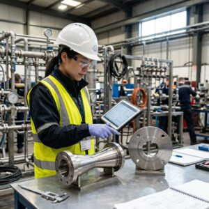

Industrial flow transmitters in service — selecting the wrong type for your medium can cascade into costly measurement errors and plant downtime.
Flow transmitters are the nerve endings of any industrial process — without precise, reliable flow data, you’re essentially running a plant on guesswork. A flow transmitter converts the mechanical signal of a flowing medium (velocity, differential pressure, mass, or acoustic response) into a standardized electrical signal — typically 4–20 mA, HART, or Modbus — that can be read, logged, and acted upon by a distributed control system (DCS) or PLC. They are indispensable in oil & gas, chemicals, water treatment, food & beverage, pharmaceuticals, and power generation.
Yet one of the most consequential and frequently underestimated decisions in instrumentation engineering is also one of the most basic: are you measuring a gas or a liquid? The physical properties that separate these two states of matter — compressibility, density variation, viscosity range, multiphase behavior — translate directly into fundamentally different sensor physics, calibration requirements, material selection, and installation geometry. Engineers who treat gas and liquid transmitters as interchangeable discover this the hard way, often in the form of 3–5% systematic measurement error, premature sensor wear, or safety-critical false readings in hazardous areas.
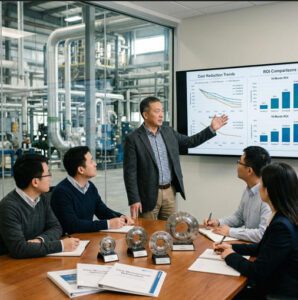
The global flow meter market reached USD 10.7 billion in 2024 and is projected to exceed USD 12.6 billion by 2029 at a CAGR of approximately 6.7%, according to MarketsandMarkets. That growth is being driven not just by new installations, but by the replacement of legacy analog transmitters with smart, diagnostics-capable devices — making transmitter selection decisions more technically nuanced than ever before.
This guide covers the core measurement principles, the physical differences that drive technology choices, the real-world performance characteristics of each transmitter class, and a practical decision framework you can use the next time you face a specification or procurement decision. By the end, you’ll have the vocabulary and the criteria to match the right technology to your medium, your process conditions, and your accuracy budget.
Fundamentals of Flow Transmitters for Gas and Liquid Applications
Core Measurement Principles: Differential Pressure, Thermal, Coriolis, and Ultrasonic
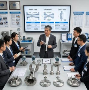
Before you can meaningfully compare gas and liquid transmitters, you need a solid handle on the four dominant sensing physics that underpin the industry. Each has a different relationship with the fluid’s physical properties, and that relationship is what determines whether a given technology is appropriate for your medium.
Differential pressure (DP) transmitters use a primary element — an orifice plate, venturi, or annubar — to create a pressure drop across the flow path. The transmitter then converts that ΔP into a flow rate via Bernoulli’s equation. DP flowmeters are the workhorses of the industry and can be applied to both gases and liquids, but their accuracy is a function of the square root of the differential signal. This means accuracy degrades at low flow — typically the bottom 25–30% of range — which is a significant constraint in highly variable processes. Their rangeability is typically 3:1 to 10:1.
Thermal mass flow transmitters measure the heat dissipated from a heated sensor element by the flowing medium. Because heat transfer is intimately linked to the specific heat capacity and mass flow of the fluid, thermal meters measure mass flow directly, without needing separate temperature and pressure compensation. This makes them outstanding for gas measurement — especially at low flow rates in compressed air, natural gas sub-metering, and stack gas monitoring applications. They are not appropriate for liquids: the high thermal conductivity of liquids creates enormous heat transfer to the pipe wall, making calibration unstable.
Coriolis mass flow transmitters induce oscillation in one or two vibrating tubes; when the fluid flows through, the Coriolis force causes a measurable phase shift proportional to mass flow rate. Coriolis meters are the gold standard for liquid measurement, offering mass flow accuracy of ±0.1% to ±0.5% of rate, direct density measurement, and complete independence from fluid viscosity changes. They can measure gas as well, but at gas densities 100–1,000× lower than liquids, the signal-to-noise ratio drops, and they become significantly more expensive per unit of measurement uncertainty than alternatives like thermal or vortex meters.
Ultrasonic flow transmitters use the transit-time method (for clean fluids) or Doppler effect (for fluids with entrained particles or bubbles) to infer velocity from acoustic signal behavior. Transit-time ultrasonic meters are excellent for clean liquids and can also be used for clean gases in large-diameter pipelines, such as custody transfer on natural gas transmission lines. Their non-intrusive or clamp-on variants offer significant advantages in retrofit applications and for corrosive or hygienic media.
▶ Video: A comprehensive guide to selecting the right flow meter for liquid, gas, and steam applications — covering technology comparison, signal output, and installation considerations.
How Gas and Liquid Properties Influence Transmitter Choice
The single most important physical difference between gases and liquids from a flow measurement standpoint is compressibility. Liquids are, for practical engineering purposes, incompressible: at a given temperature, a liter of water flowing into a pipe is a liter flowing out, regardless of pressure. Gases are not. Reduce the pressure in a gas pipeline by 10% and the volumetric flow rate changes substantially, even if the mass flow rate stays constant. This is why gas flow transmitters must incorporate — or be paired with — pressure and temperature compensation to convert from actual volumetric flow (AVF) to standard volumetric flow (SVF) or mass flow. Failing to do this is one of the most common sources of systematic error in gas metering applications.
A second critical distinction is density magnitude and variation. Liquid densities typically range from 700 kg/m³ (light hydrocarbons) to 1,200+ kg/m³ (concentrated chemical solutions). Gas densities at typical operating conditions range from 0.7 kg/m³ (methane at atmospheric pressure) to around 50–100 kg/m³ in high-pressure gas systems. This four-orders-of-magnitude difference in inertial force directly affects the sizing of sensing elements, the selection of wetted materials (a sensor optimized for water pressure will be over-engineered and over-priced for gas), and the detection thresholds of the transmitter electronics.
Viscosity is a third differentiator. Liquids can range from near-water viscosity (1 cP for water) to tens of thousands of centipoise for heavy crude oil or polymer melts. High viscosity affects Reynolds number and therefore the linearity of velocity profiles in turbine and DP meters. Gas viscosities are typically three orders of magnitude lower than liquids, which means viscosity correction is rarely necessary in gas measurement but is often critical in liquid measurement — particularly in custody transfer applications for crude oil.
Common Performance Metrics: Accuracy, Repeatability, and Turndown
Three metrics dominate every transmitter data sheet and every procurement conversation: accuracy, repeatability, and turndown ratio. Accuracy is the maximum deviation between the measured value and the true value, expressed as ±% of rate or ±% of full span — and you should always insist on “% of rate” specifications, because “% of full span” can hide poor performance at low flow rates. Repeatability is the transmitter’s ability to return the same reading given the same flow conditions, and it matters more than accuracy in applications where you’re looking for process changes rather than absolute values. Turndown ratio (also called rangeability) is the ratio of maximum to minimum measurable flow with maintained accuracy — a Coriolis meter may achieve 100:1 or better, while an orifice plate is typically limited to 5:1 to 10:1.
Sources: Engineering Toolbox; Fuji Electric; manufacturer specifications. Turndown ratios are typical maximums under optimal conditions.
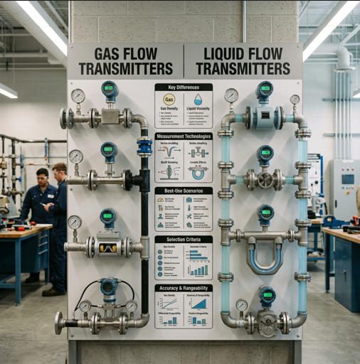
Key Differences Between Gas and Liquid Transmitters
Signal Types and Sensing Technologies Favored by Gas vs Liquid
In practice, the instrumentation industry has converged on preferred sensing technologies for each medium based on decades of field experience. For gas measurement, thermal mass, vortex, and differential pressure (with multi-variable transmitters for compensation) are the dominant choices. In custody transfer applications for natural gas — where even 0.1% measurement error at a major metering station can represent millions of dollars of revenue impact — ultrasonic and Coriolis meters have gained significant ground since the 2000s, validated against standards like AGA-9 (ultrasonic) and AGA-11 (Coriolis).
For liquid measurement, electromagnetic (mag) meters dominate conductive liquid applications, used in roughly 30% of new liquid transmitter installations worldwide. Coriolis remains the benchmark for mass flow accuracy in high-value liquid streams (refined chemicals, custody transfer hydrocarbons, pharmaceutical batching). Turbine meters are widely deployed in clean, low-viscosity hydrocarbon streams. Ultrasonic meters, particularly clamp-on variants, are increasingly specified for retrofits where cutting the pipe is cost-prohibitive.
The signal output architecture of gas and liquid transmitters has largely converged around 4–20 mA with HART superimposed for legacy integration, Modbus RTU/TCP for modern PLC connectivity, and Profibus/FOUNDATION Fieldbus for DCS architectures in larger process plants. However, gas transmitter installations in custody transfer often require dedicated flow computers to perform AGA or ISO flow calculation algorithms — a layer of signal processing that is rarely necessary in liquid measurement, where volumetric flow is the primary deliverable.
Impact of Compressibility, Density, and Viscosity on Readings
Consider what happens in a natural gas distribution network when line pressure fluctuates from 60 bar to 72 bar across a shift: a volumetric flow transmitter without pressure compensation will overstate the volumetric flow rate by 20% — a massive error that goes unnoticed until a billing reconciliation flags the discrepancy. This is the compressibility problem in sharp relief, and it explains why every reputable gas flow transmitter either incorporates an onboard pressure sensor for AV-to-SV conversion or requires a companion pressure tap and temperature well connected to a separate multi-variable transmitter or flow computer.
For liquids, the density effect is more subtle but equally consequential in custody transfer. Crude oil at 20°C may have a density of 860 kg/m³; at 50°C (after passing through a heat exchanger), it may be 835 kg/m³. If you’re billing by volume but need to report at a standard reference temperature (typically 15°C or 60°F per API standards), your transmitter or associated flow computer needs a calibrated density input. This is one reason that Coriolis meters, with their simultaneous measurement of both mass flow and fluid density, have become the preferred choice for refined hydrocarbon custody transfer despite their significantly higher capital cost versus DP or turbine alternatives.
Material and Installation Considerations Specific to Each Medium
Gas transmitters typically operate at far higher pressures than liquid transmitters in comparable process stages — it’s not uncommon to see natural gas measurement at 100–200 bar in transmission pipelines. This imposes severe requirements on pressure body ratings, seal integrity, and the selection of compatible elastomers. Fugitive emission standards (ISO 15848, EPA Regulation 40 CFR Part 60) add another layer of specification for gas installations in the oil & gas sector, requiring qualified valve packing and transmitter housing seals to minimize atmospheric releases.
Liquid transmitters face their own installation challenges: most electromagnetic meters require the pipe to run full at all times (partial pipe flow causes reading failure), and many require upstream/downstream straight-run lengths to develop a fully developed velocity profile. Vortex meters for liquids typically require 10–20 diameters of straight pipe upstream, while Coriolis meters — owing to their mass-based measurement principle — are insensitive to velocity profile and can be installed almost anywhere, which is one reason they command such a strong presence in retrofits of congested pipework.
Strengths and Limitations of Gas Flow Transmitters

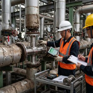
Gas flow transmitters in pipeline duty — thermal mass and vortex technologies dominate in gas distribution and process gas applications.
When Gas Transmitters Excel
Gas flow transmitters in the thermal mass class shine in applications where mass flow accuracy at low flow rates is critical and process gas composition is well-defined and stable. A biogas facility in Germany, for example, might use thermal mass meters on digester gas outlet headers to accurately track methane yield — data that feeds directly into energy billing and process optimization. At flow velocities as low as 0.1 m/s in a 100 mm pipe, thermal mass meters maintain accuracy well within ±1.5% of rate. Competing technologies like vortex meters lose signal below a Reynolds number threshold, making them unsuitable at these conditions.
For larger-diameter, higher-flow applications in natural gas distribution, gas processing, and fuel gas systems, vortex meters offer an excellent combination of accuracy (±0.5–1.5% of rate), no moving parts, low maintenance requirements, and wide temperature and pressure ratings. A petrochemical complex running fuel gas headers at 10–30 bar typically favors vortex meters precisely because of this maintenance advantage: a refinery that switched from turbine meters to vortex meters on six fuel gas headers in 2019 reported a 40% reduction in annual calibration labor and zero in-service failures over four years, compared to an average of 1.2 bearing failures per meter-year with turbines.
Multi-path ultrasonic meters are the instrument of choice in custody transfer of natural gas on transmission pipelines, where the combination of ±0.25% accuracy, no pressure drop, and continuous self-diagnostic capability meets the requirements of AGA Report No. 9. Many fiscal metering stations now run dual-configuration setups with both an ultrasonic meter and a check standard, with automatic alarm when the two diverge by more than 0.1%, an architecture that would be economically unviable with older DP or turbine technologies.
Limitations to Watch: Pressure Drop, Clogging, and Drift
Gas flow transmitters have three characteristic failure modes that field engineers learn to anticipate. The first is excessive pressure drop through intrusive sensing elements. In gas systems where line pressure is a scarce resource (e.g., low-pressure distribution networks or biogas systems running at a few millibars above atmospheric), even the modest ΔP of a vortex shedder or orifice plate can represent a meaningful fraction of the available driving head. This is why ultrasonic meters, which introduce essentially zero permanent pressure loss, are specified despite their higher capital cost in low-pressure gas distribution applications.
The second failure mode is condensate and hydrocarbon dropout. Natural gas that cools below its dew point deposits liquid hydrocarbons and water in the flow element — a problem seen with particular frequency in outdoor above-grade installations in cold climates. Condensate accumulating in the impulse lines of a DP transmitter creates a liquid leg that offsets the ΔP signal, potentially generating a 2–5% positive bias in the flow reading that can persist for weeks before it’s identified in calibration. Proper installation of moisture separators, heat tracing, and the use of self-draining impulse line geometry (per ASME MFC-3M recommendations) are the engineering countermeasures.
The third is zero drift in thermal mass transmitters. The zero-point offset — the signal output when flow is truly zero — is temperature-sensitive and can creep over time, particularly in applications with significant ambient temperature swings. Thermal meters in outdoor gas measurement applications should be specified with a zero-drift specification of less than ±0.5% of full scale per year, and annual zero-flow verification should be built into the maintenance schedule.
Strengths and Limitations of Liquid Flow Transmitters
When Liquid Transmitters Excel
Electromagnetic flow meters are the dominant technology in liquid measurement and for good reason: for any electrically conductive liquid — water, wastewater, acids, alkalis, slurries — they offer an outstanding combination of accuracy (typically ±0.2–0.5% of rate), zero pressure drop, full bore without obstruction, complete insensitivity to viscosity, density, and temperature, and liner/electrode material options that cover virtually every corrosive medium from concentrated sulfuric acid to seawater. A municipal water authority running 600 mm mains at a water treatment plant expects their electromagnetic meters to run continuously for 10–15 years with only periodic electrode cleaning and no moving parts to replace. In practice, this is routinely achieved.
In the water/wastewater sector, electromagnetic meters measure everything from raw influent with 2–3% solids content to final effluent and chemical dosing streams. Their ability to handle suspended solids without clogging or accuracy degradation makes them vastly superior to any intrusive technology for this application. A large-scale desalination plant in the Middle East, for instance, might have 200+ electromagnetic meters across its feed water, brine, and product water circuits, monitored continuously to balance permeate recovery and detect membrane integrity issues through subtle flow deviations.
For high-value, high-precision liquid measurement in chemical processing and pharmaceutical manufacturing, Coriolis meters are increasingly displacing both turbine and DP meters. A specialty chemicals plant batching a catalyst at a target of 4,250 kg/batch might have historically tolerated a ±15 kg batch-to-batch variance from a turbine meter. After switching to a Coriolis meter with mass flow accuracy of ±0.15% of rate, they reduced batch variance to ±3 kg — translating to less off-spec product, tighter yield control, and demonstrable savings in raw material costs that justified the capital investment within 18 months.
Limitations to Watch: Air Entrainment, Fouling, and Temperature Effects
Liquid flow transmitters are not without their characteristic failure modes. Air entrainment is the single most common cause of unexplained measurement error in liquid applications. When air or gas bubbles are present in the liquid stream — from pump cavitation, pressure drops across control valves, or inadequate upstream degassing — electromagnetic meters generate a fluctuating or inflated reading because bubbles momentarily disrupt the magnetic field across the measuring tube. The practical fix is to locate electromagnetic meters at points in the system where the pipe is guaranteed to remain full and bubble-free — typically downstream of pumps, below the high point of a U-loop, or after an in-line air eliminator.
Electrode fouling is the dominant long-term reliability issue for electromagnetic meters in wastewater, food processing, and mineral slurry applications. Biofilm, scale, and precipitated minerals on the electrodes change the contact impedance and progressively bias the reading. Modern electromagnetic transmitters with automatic electrode cleaning (AC excitation with periodic diagnostic pulses) can detect and compensate for early-stage fouling, but there is no substitute for periodic manual inspection and cleaning in severe service. A mine site dewatering application with high dissolved solids might see measurable electrode fouling within 30–60 days, requiring scheduled cleaning as part of the preventive maintenance regime.
Temperature effects on liquid density are important in applications where volumetric measurement must be converted to mass or to a standard reference condition. An inline temperature compensation input is standard on most modern liquid flow transmitters, but it only helps if the temperature sensor is installed and calibrated correctly — an obvious point that is nevertheless frequently overlooked in system commissioning.
Sizing, Selection, and Installation Best Practices

Proper sizing is as important as technology selection — an over-sized transmitter running at 10% of its range introduces avoidable measurement uncertainty.
Key Sizing Criteria: Flow Range, Pressure, and Temperature
Transmitter sizing begins with the hydraulic envelope of the application: the minimum, normal, and maximum flow rates. A common and costly mistake is to size the transmitter based on the maximum conceivable flow rather than the normal operating flow. This results in a transmitter that spends 90% of its service life operating in the bottom quartile of its range — exactly where accuracy is worst, particularly for DP and turbine technologies. The rule of thumb used by experienced instrumentation engineers is to size so that the normal operating flow falls at 60–70% of the meter’s range, providing headroom for surges while ensuring the meter operates at its rated accuracy under typical conditions.
For gas applications, sizing requires the application of a gas-specific sizing factor. The same physical meter that measures 500 Nm³/h of air at 1 bar absolute will meter a very different actual volumetric rate if the gas density is substantially different — natural gas at 40 bar has a density roughly 40 times higher than at 1 bar, meaning velocity through the meter is 40 times lower for the same mass flow, and a meter sized for low-pressure gas will be wildly over-ranged at high pressure. Most manufacturers provide gas sizing tools that account for operating pressure, temperature, and gas composition to ensure the selected meter operates in the sweet spot of its turndown range.
Temperature and pressure ratings must be matched to the process — not just the nominal operating conditions, but the worst-case excursions during startup, CIP (clean-in-place), or process upsets. A steam-traced liquid line may briefly reach 130°C during a heat trace malfunction; a gas transmitter on a compressor outlet will see pressure surges at startup. Specifying a transmitter with ratings that just barely meet the normal operating conditions is a false economy.
Installation Tips: Vertical/Horizontal Orientation and Straight-Run Requirements
Installation geometry has a disproportionate impact on measurement accuracy and long-term reliability. For liquid electromagnetic meters, the pipe must run completely full: the preferred orientation is therefore vertical, upward flow, which guarantees a full pipe at all flow rates, eliminates air entrainment, and ensures particles in slurries do not settle on the bottom electrode. Horizontal installation is acceptable in clean, single-phase liquid service but should be avoided in slurry, wastewater, and aerated liquids.
For gas vortex meters, the manufacturer-specified upstream straight run is non-negotiable. Vortex shedding frequency is a function of velocity profile symmetry; a partially developed profile caused by an upstream elbow within 5 diameters can shift the meter’s K-factor by 1–3%, an error that is invisible during calibration (which is done in straight-run conditions) but permanent in service. Where straight run is unavailable, flow conditioners (tube bundles, perforated plates) can re-establish a developed profile in 5–10 diameters instead of the 20+ required without conditioning, at the cost of a small additional pressure drop.
For differential pressure transmitters on gas, the orientation of impulse lines is critical. On gas service, impulse lines should slope continuously downward from the transmitter to the process connection, with a low-point drain valve, to prevent condensate accumulation. On liquid service, impulse lines should slope continuously upward to prevent gas pockets. The classic trap of running horizontal impulse lines — which creates neither condition — is responsible for more chronic DP transmitter inaccuracy than almost any other installation error.
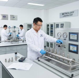
Calibration and Verification Steps
Factory calibration traceable to national metrology standards (NIST, PTB, NEL, NMi) is the foundation of transmitter accuracy. However, the calibration is only valid at the factory test conditions — typically clean water for liquid meters and air or nitrogen for gas meters. For custody transfer or safety-critical applications, a full in-situ calibration or meter proving (against a certified master meter or displacement prover) should be performed after installation, before commissioning. For most process applications, a zero-flow verification check (confirming the output is 4.00 mA with no flow) and a single-point check against a portable clamp-on ultrasonic meter provides sufficient confidence for commissioning without the cost of a full proving.
Accuracy, Reliability, and Maintenance Considerations
Routine Calibration Schedules and Drift Management
Industry practice for calibration intervals reflects both the technology’s inherent drift characteristics and the consequence of undetected error. Custody transfer meters are typically proved at intervals of 1–6 months, with shorter intervals early in service life to establish the meter’s drift signature. Process control meters in non-fiscal duty — monitoring, batch control, utility accounting — are typically calibrated annually or biannually. Electromagnetic meters in clean water service, where fouling and wear are minimal, may be operated for 3–5 years between formal calibrations with only periodic zero checks.
Drift is the gradual, systematic change in a transmitter’s output that occurs even in the absence of any known process disturbance. Gas thermal mass meters exhibit the highest drift rates of the common technologies, primarily due to sensor contamination and zero-point thermal sensitivity. Coriolis meters have the lowest drift rates: the physics of tube vibration frequency are extraordinarily stable over time, and many high-end Coriolis meters have published drift specifications of less than ±0.05% of rate per year, which means a three-year calibration interval is technically defensible in many process applications.
Preventive Maintenance for Gas vs Liquid Systems
Gas transmitter maintenance is dominated by the ancillary components rather than the sensor itself: impulse line drain/purge operations, moisture separator element replacement, filter element changes on thermal mass meter inlets, and periodic inspection of sensor tips for corrosion or debris accumulation. The sensor electronics in most modern gas transmitters — with no moving parts in the thermal, ultrasonic, or vortex sensing element — are inherently low-maintenance, with mean times between failure (MTBF) commonly exceeding 50,000 hours.
Liquid transmitter maintenance is more sensor-focused: electrode inspection and cleaning for electromagnetic meters, impeller bearing inspection and replacement in turbine meters (typically every 2–4 years depending on fluid cleanliness), and vibrating tube inspection for any external corrosion or erosion at pipe supports in Coriolis installations. The most cost-effective maintenance strategy for liquid transmitters is condition-based monitoring — using the transmitter’s own diagnostic outputs (empty pipe detection, electrode impedance trending, vibration amplitude in Coriolis) to schedule maintenance only when the data indicates it is necessary, rather than on a fixed calendar.
Diagnostics and Remote Monitoring Options
Modern smart transmitters from manufacturers including Jade Ant Instruments embed continuous self-diagnostic functions that can detect electrode coating, empty pipe, low signal strength, magnetic coil failure, and excessive noise — all conditions that would have gone undetected on legacy analog transmitters until the next scheduled calibration. These diagnostics are accessible via HART communicators, asset management software (such as ABB’s Field Information Manager or Emerson’s AMS), or via OPC-UA in newer IIoT-connected architectures.
The practical impact is significant. A pulp & paper mill with 85 electromagnetic meters on its process water circuits integrated HART diagnostic data into its DCS historian and programmed alarms for electrode impedance outside the 50–500 kΩ normal range. Over the first year of operation, the system flagged 12 incipient electrode fouling events, all of which were resolved with scheduled cleaning during planned downtime windows — compared to three unplanned production interruptions in the previous year caused by undetected fouling driving meters into error state.
Operating Conditions and Safety Implications
Temperature, Pressure, and Vibration Tolerances
The operating envelope of a flow transmitter must be matched to the most demanding conditions it will experience in service, not the average. Temperature is perhaps the most impactful factor in transmitter accuracy and longevity. Most standard industrial transmitters are rated for process temperatures from –40°C to +125°C or +180°C. High-temperature gas service — process gas lines downstream of heat exchangers, saturated steam measurement, pyrolysis gas headers — may require remote-seal configurations, cooling fins, or transmitter housings with extended neck assemblies to protect the electronics from heat soak. In cryogenic liquid service (LNG, liquid nitrogen, liquid oxygen), transmitters must be specifically engineered for sub-zero body temperatures to prevent condensate ice formation and seal brittleness.
Vibration is an underappreciated threat, particularly for Coriolis meters, which are sensitive to external vibration that couples into their tube resonance frequency. A Coriolis meter installed on a compressor skid without proper vibration isolation can show significant noise and instability in its mass flow output, even though the meter itself is undamaged. Vibration isolation mounts, adequate pipe support spacing, and a minimum separation from vibration sources (compressors, pumps, fans) of 2–3 meters are standard precautions in high-vibration installations.
Safety and Compliance Implications for Explosive Atmospheres
Any flow transmitter in a zone where flammable gases or dusts may be present must carry the appropriate explosion protection certification. In the European Union and many international markets, this means ATEX certification (Directive 2014/34/EU); in North America, equivalent requirements are covered by NFPA 70 (NEC) and CSA certifications. The protection concept (intrinsic safety Ex ia/ib, explosion-proof Ex d, increased safety Ex e, or purge-and-pressurize Ex p) must match the zone classification and the gas group of the hazardous atmosphere. Gas flow transmitters in natural gas compression stations, fuel gas systems, and offshore topside applications must invariably be specified with at least Ex d or Ex ia certification — a requirement that is sometimes overlooked in the rush of a project’s early procurement phase and cannot be retrofitted without full re-certification.
For liquid transmitters in chemical plants, the relevant safety dimensions extend beyond explosion protection to include materials compatibility (metal ion contamination in pharmaceutical grade water, stress corrosion cracking of stainless steel by chloride-rich process streams) and the hygienic design requirements of 3A and EHEDG standards in food and beverage applications.
Impact of Aging Components on Safety and Performance
Transmitter aging does not follow a simple degradation curve. Most failure modes are “bathtub” distributed: a higher failure rate in the first few months of service (infant mortality from manufacturing defects), a long period of low and stable failure rate, followed by increasing failure rate as mechanical wear, electronic component aging, and seal degradation accumulate. For gas transmitters in safety instrumented systems (SIS), IEC 61511 requires systematic proof testing at defined intervals to confirm the transmitter’s probability of failure on demand (PFD) remains within the safety integrity level (SIL) target. Ignoring proof test requirements in a SIS is not just poor practice — it is a legal and regulatory exposure.
Best-Use Scenarios and Application Case Studies
| Application | Medium | Recommended Technology | Key Driver | Typical Accuracy |
|---|---|---|---|---|
| Natural gas custody transfer (transmission) | Gas | Multi-path Ultrasonic | AGA-9 compliance, zero ΔP, self-diagnostics | ±0.25% of rate |
| Biogas / landfill gas metering | Gas | Thermal Mass | Low flow sensitivity, mass measurement, wide turndown | ±1.0–1.5% of rate |
| Fuel gas distribution (refinery) | Gas | Vortex | No moving parts, high temp/pressure rating, low maintenance | ±0.5–1.0% of rate |
| Compressed air sub-metering | Gas | Thermal Mass or Vortex | Wide turndown, low cost per point | ±1.0–2.0% of rate |
| Municipal water distribution | Liquid | Electromagnetic | Zero pressure drop, long service life, handles suspended solids | ±0.2–0.5% of rate |
| Wastewater / sludge flow | Liquid | Electromagnetic | Full bore, tolerates solids, liner material versatility | ±0.5% of rate |
| Crude oil / refined product custody transfer | Liquid | Coriolis or Turbine | API MPMS compliance, mass or volumetric accuracy | ±0.1–0.25% of rate |
| Chemical / pharmaceutical batching | Liquid | Coriolis | Direct mass flow, density, temperature in one device | ±0.1–0.2% of rate |
| Desalination (feed water, brine, product) | Liquid | Electromagnetic | Handles high TDS, corrosion-resistant liners, zero obstruction | ±0.2–0.5% of rate |
| Cooling water loops | Liquid | Electromagnetic or Ultrasonic (clamp-on) | Non-intrusive option, low maintenance, retrofit-friendly | ±0.5–2.0% of rate |
| Slurry / multiphase / entrained gas | Liquid (complex) | Coriolis or Doppler Ultrasonic | Density measurement, insensitivity to two-phase flow | ±0.3–1.5% of rate |
Gas Flow Transmitter Scenarios: Natural Gas, Process Gas, Fuel Gas
In a large natural gas distribution utility, fiscal metering stations (city gate stations) are the commercial interface between the transmission network and the distribution system — the point where gigajoules of gas change hands and are invoiced. A billing error of 0.5% on a station flowing 500,000 Nm³/h represents approximately USD 45,000 per year at typical European gas prices (2025 basis). This is why these stations universally employ multi-path ultrasonic meters operating under AGA-9, with secondary check meters and continuous uncertainty monitoring. The investment in a USD 80,000 ultrasonic meter installation pays for itself in measurement confidence within months.
Process gas applications in refining and petrochemicals — hydrogen make-up to hydrotreaters, fuel gas header balance, flare gas measurement for environmental reporting — have driven the specification of thermal mass meters for their combination of high turndown (100:1 is achievable with modern designs), direct mass flow without separate P/T compensation in moderate-pressure applications, and suitability for low-velocity, small-diameter lines. Environmental regulations requiring continuous emissions monitoring (CEMS) have created an entirely new demand category for low-uncertainty gas flow measurement that is still evolving in its technical standards.
Liquid Flow Transmitter Scenarios: Crude Oil Terminals, Desalination, Cooling Loops
At a crude oil loading terminal, the metering system is the legal instrument of commerce: the volume transferred and reported to the terminal’s meter station determines the invoice to the tanker operator. A terminal loading 100,000 barrels per day at USD 75/barrel — a very conservative throughput for a mid-size export terminal — has a daily invoice value of USD 7.5 million. At 0.1% measurement uncertainty (the tolerance of a well-maintained Coriolis or turbine prover system), the maximum daily billing exposure is USD 7,500. Every incremental improvement in meter uncertainty directly reduces commercial risk for both buyer and seller. This economic reality explains why the oil & gas industry has been the technology pull behind Coriolis meter development for the past 30 years.
In large-scale desalination plants, electromagnetic meters manage the water balance across pre-treatment, RO train feeds, brine recycle, and product water headers. The demanding aspect is the chloride content of the feed seawater: a standard 316L stainless steel electrode will corrode in months on a 35,000 ppm chloride feed. The correct specification is Hastelloy C-276 or titanium electrodes, with a hard rubber or PTFE liner matched to the pH range of the process streams. Getting these material selections wrong is the type of costly mistake that proper engineering specification — the kind supported by an experienced instrumentation team like Jade Ant Instruments’ electromagnetic flow meter engineers — is designed to prevent.
Hybrid and Challenging Applications: Slurries, Multiphase, and Entrained Gases
Some of the most technically demanding flow measurement applications involve fluids that are neither cleanly gas nor cleanly liquid. Slurries (solids suspended in a liquid carrier), aerated liquids (gas bubbles in a liquid), and wet gases (liquid droplets in a gas stream) all challenge the assumptions built into conventional single-phase flow transmitters. In these applications, measurement uncertainty can easily reach 3–10% even with high-quality instrumentation unless the technology and installation are carefully chosen.
For mining slurries with up to 50% solids by weight, electromagnetic meters with ceramic liners and tungsten carbide electrodes are the state of the art, achieving ±0.5% of rate despite the abrasive nature of the medium. For wet gas streams in upstream oil & gas, multiphase flow meters (MPFMs) combining gamma-ray densitometry, microwave permittivity sensing, and differential pressure provide all-in-one measurement of gas, water, and oil fractions without test separation — a technology that has transformed production testing in deepwater fields where installing and maintaining a conventional test separator would cost tens of millions of dollars.
Troubleshooting and Common Pitfalls to Avoid

Troubleshooting flow transmitter issues requires a systematic approach: distinguish measurement errors from process disturbances before assuming instrument failure.
Signals That Indicate Incorrect Gas vs Liquid Selection
Some of the most persistent measurement problems in process plants are caused not by instrument failure but by the wrong technology being applied to the wrong medium. Several field symptoms are highly diagnostic of this error. If a flow transmitter shows a persistent positive reading bias that increases with process pressure, the root cause is almost certainly a gas-service transmitter compensating incorrectly for a higher-density liquid that has flooded the measurement element — or conversely, a liquid-service transmitter in gas duty where condensed liquid is creating a false differential pressure. If a Coriolis meter shows excessive signal noise and unstable density readings, the fluid in the tubes likely contains entrained gas — the Coriolis effect is attenuated by gas bubbles because their mass and Coriolis force contribution is negligible, disrupting the phase shift signal.
If an electromagnetic meter in liquid service reads significantly higher than an independent check measurement and the discrepancy grows with flow rate, the most likely cause is air entrainment creating a slug flow pattern that inflates the measured velocity. Moving the meter to a lower elevation (ensuring full pipe) or adding an upstream air eliminator typically resolves the problem without any change to the instrument itself.
Clogging, Condensation, and Phase Separation Issues
Clogging is primarily a liquid transmitter problem. Intrusive meters — turbine, vortex, DP with a primary element — are vulnerable to blockage by fibrous material (paper pulp, municipal wastewater), polymerizing fluids (certain monomers that react at low flow), and crystallizing slurries (evaporator circuits in chemical plants). The engineering response is generally to select a meter with a full-bore, obstruction-free measuring element — electromagnetic, transit-time ultrasonic, or Coriolis — which eliminates the clogging mechanism. Where an intrusive meter is already installed, upstream strainers and periodic back-flushing provisions are the practical maintenance countermeasures.
Condensation in gas transmitter housings is caused by warm, moist ambient air entering the housing and condensing on the cooler electronics. Beyond the obvious corrosion risk, condensation can track along circuit board surfaces and create intermittent resistive paths that generate spurious signal behavior. Modern transmitter housings are specified with IP66 or IP67 ingress protection ratings, but every entry point — cable gland, conduit hub, terminal block cover — is a potential condensation pathway if not correctly sealed. The best practice is to use sealed, gel-filled cable glands and to ensure conduit entries are not oriented upward (which allows moisture to drain into the housing from the conduit run).
Sensor Drift and How to Isolate Causes Quickly
When a flow transmitter reading drifts away from its historical baseline without any corresponding process change, the first question is always: is the drift in the sensor, or in the process? The fastest way to answer this — short of removing the meter for bench calibration — is to compare the suspect transmitter with an independent check measurement (a portable clamp-on ultrasonic meter, a test turbine in a spool piece, or comparison with a flow balance calculation). If the discrepancy is confirmed, the second step is to check the transmitter’s own diagnostic outputs: is there a low electrode signal (fouling in a mag meter), a high noise level (vibration or entrained gas), or an electronics temperature alarm (sensor drift due to temperature)? Modern transmitters from quality manufacturers like Jade Ant Instruments make this diagnostic workflow significantly faster through built-in verification tools accessible without removing the meter from service.
Emerging Trends and Future Directions
IoT, Smart Diagnostics, and Predictive Maintenance
The integration of industrial flow transmitters into IIoT (Industrial Internet of Things) architectures is one of the most significant structural changes underway in instrumentation engineering. Smart transmitters with onboard microprocessors have been available since the 1980s, but the emergence of standardized, low-cost wireless protocols (WirelessHART, ISA100.11a, IO-Link) and cloud-based process data platforms has made it economically viable to stream diagnostic data from hundreds of field instruments to centralized analytics engines. The global predictive maintenance market is growing at approximately 17% CAGR through 2028, with flow transmitter health monitoring representing one of the highest-value use cases owing to the high cost of undetected measurement error versus the low cost of a connectivity module.
Practical implementations are already delivering measurable value. A major European chemical plant connected 340 smart transmitters (including 120 electromagnetic meters and 60 Coriolis meters) to a cloud-based asset management platform in 2023. Over the first 18 months, the system identified 23 instances of progressing sensor degradation before they caused process or measurement failures — eight of which would have required production shutdowns to investigate had they not been caught early. The estimated avoided downtime cost over 18 months was approximately EUR 420,000 against a connectivity and software investment of EUR 85,000.
Advances in Non-Contact Measurement and Multi-Parameter Meters
Non-contact and minimally-intrusive flow measurement technologies are advancing rapidly, driven by the desire to eliminate the maintenance costs and process interruption associated with in-line sensor elements. Clamp-on ultrasonic meters have improved dramatically in accuracy and ease of setup over the past decade: modern clamp-on systems from leading manufacturers achieve ±1–2% of rate for clean liquids in controlled conditions — sufficient for energy accounting and process monitoring, though not yet for custody transfer. Guided wave radar and microwave technologies are entering the flow measurement space for applications involving aggressive chemicals and high temperatures where even a sensor insertion is unacceptable.
Multi-parameter transmitters — devices that simultaneously measure flow, temperature, pressure, and density or gas quality — are reducing the instrument count in complex installations. A single Coriolis transmitter can output mass flow, volumetric flow, fluid density, fluid temperature, and net oil/water/gas fractions in a multiphase stream, replacing what would previously have been four or five separate instruments with separate impulse lines, signal conditioners, and maintenance schedules. This convergence is particularly valuable in offshore applications where instrument weight, space, and intervention cost are at a premium.
Industry Standards and Interoperability
Standardization in flow measurement is an ongoing process driven by the increasing complexity of data integration requirements. The ISA and IEC are actively developing standards for smart transmitter interoperability (IEC 61987, IEC 62769 FDI), which aim to make the configuration, diagnostics, and data from any manufacturer’s smart transmitter accessible through a common software framework — eliminating the current situation where a plant with instruments from five different manufacturers needs five different asset management software tools. For end-users, the business case for standardized interoperability is compelling: lower software license costs, a single operator interface, and the ability to run vendor-neutral analytics across the entire instrument population.
Conclusion and Practical Decision Checklist
Market
Share
Source: MarketsandMarkets, Fortune Business Insights, Mordor Intelligence (2024–2025 estimates). Figures are approximate market-share ranges averaged across reports.
Quick-Reference Decision Tree for Gas vs Liquid Transmitters
🔍 Flow Transmitter Selection Decision Tree
- Define your medium: Is it a gas, liquid, or mixed/multiphase? If multiphase, go to Step 7.
- For gas: Is pressure compensation required? (Yes for volumetric measurement of compressible gas.) → Select a multi-variable transmitter or flow computer pairing.
- For gas at low flow / small diameter: Is mass flow accuracy at low velocity required? → Thermal mass meter.
- For gas at medium-high flow / larger diameter / high-pressure: Is no pressure drop essential? → Multi-path ultrasonic. Is moderate cost priority? → Vortex.
- For liquid — conductive (water, wastewater, acids, alkalis): Is zero pressure drop / full bore required? → Electromagnetic.
- For liquid — non-conductive (hydrocarbons, solvents) or mass flow required: Is highest accuracy the priority? → Coriolis. Is moderate accuracy with lower cost acceptable? → Turbine (clean, low-viscosity) or DP.
- For multiphase / slurry / entrained gas: Consult a specialist application engineer. Options include Coriolis (slurries), Doppler ultrasonic (slurries), or a dedicated multiphase flow meter (oil/water/gas).
- Check hazardous area classification: Confirm ATEX/IECEx/NEC area zone and ensure specified transmitter carries the correct certification.
- Verify straight-run requirements: Confirm available upstream/downstream straight pipe against manufacturer minimum specification.
- Size the transmitter: Target 60–70% of range at normal flow rate. Confirm turndown covers minimum/maximum flow envelope.
Cost of Ownership Considerations: CapEx vs OpEx
The purchase price of a flow transmitter is rarely the best basis for procurement decisions, yet it dominates many purchasing conversations. Total cost of ownership (TCO) analysis consistently reveals that for industrial flow transmitters with service lives of 10–20 years, the maintenance, calibration, and downtime costs typically exceed the initial capital cost by a factor of 2–5×. A USD 1,200 turbine meter with USD 400/year maintenance costs over a 15-year life has a TCO of USD 7,200 — versus a USD 3,500 electromagnetic meter with USD 80/year maintenance costs and a TCO of USD 4,700, a 35% lower TCO despite costing 3× more upfront. This analysis is one reason experienced engineers increasingly argue for technology-first rather than price-first selection.
For organizations building new instrumentation specifications or reviewing their installed base, engaging directly with manufacturers who provide full lifecycle support — calibration documentation, spare parts, firmware updates, and application engineering support — is critical to realizing the long-term TCO advantage of smart transmitter technology. Jade Ant Instruments offers electromagnetic, vortex, turbine, and ultrasonic flow meter solutions with HART and Modbus communication, ISO-certified calibration traceability, and OEM/ODM customization to support both standard and challenging flow measurement applications across the oil & gas, chemical, water treatment, and utility sectors.
Recommended Next Steps for Engineers and Procurement
Armed with the framework in this guide, the most productive next steps are to conduct a formal application review of every flow transmitter on your specification or installed base, validating that the technology selected is genuinely appropriate for the medium and process conditions. For new projects, require your instrumentation vendor or EPC to document the justification for each technology selection in the instrument data sheet — not just the model number, but the reasoning. For existing installations where chronic measurement problems have been accepted as normal, perform a systematic audit against the decision criteria above: the root cause of most persistent measurement problems can be identified and corrected without replacing the meter, simply by adjusting installation, calibration, or maintenance practices.
Frequently Asked Questions (FAQs)
1. How do temperature and pressure affect gas vs liquid transmitter accuracy?
For gas flow transmitters, temperature and pressure directly determine the gas density, which governs the relationship between actual volumetric flow and standard (or mass) flow. A gas transmitter that does not incorporate real-time pressure and temperature compensation will introduce errors proportional to the deviation of actual conditions from the calibration reference state — for natural gas at 40 bar, a 5 bar pressure swing represents a ~12.5% density change and therefore a ~12.5% flow measurement error if uncompensated. For liquid transmitters, temperature effects are more subtle: liquid density changes are smaller in magnitude (typically 0.03–0.05% per °C for water), but temperature also affects viscosity, which can influence the calibration of turbine and vortex meters if the fluid viscosity shifts outside the calibration range. Modern multi-variable transmitters address both issues by incorporating onboard temperature and pressure sensors whose data feeds the transmitter’s internal flow calculation engine.
2. When is an ultrasonic transmitter preferable to a differential pressure transmitter for liquids?
Ultrasonic transmitters outperform differential pressure in liquid service whenever any of four conditions are present: (1) zero permanent pressure loss is required (critical in low-pressure water networks or energy-recovery applications); (2) the liquid contains suspended solids that would erode or clog the primary element of a DP meter; (3) a wide turndown ratio is needed — ultrasonic meters achieve 40:1 or better, versus 5:1 for a standard orifice plate; or (4) the meter must be non-intrusive, as in retrofit applications where cutting the pipe is prohibitively expensive or the process fluid is too hazardous for conventional installation. The trade-off is that ultrasonic meters require a minimum liquid conductivity (for transit-time variants) and perform less well in fluids with entrained gas or high particle loading — conditions where Doppler ultrasonic or electromagnetic meters are the more robust choice.
3. What maintenance practices extend flow transmitter life in harsh environments?
The highest-impact maintenance practices are: (1) regular inspection and cleaning of wetted surfaces — electrodes in electromagnetic meters, sensor tips in thermal mass meters, and shedder bars in vortex meters; (2) maintaining IP-rated housing integrity by checking cable gland seals and housing O-rings annually, especially in outdoor installations subject to UV degradation; (3) verifying zero-flow output periodically (achievable with zero-flow verification functions in smart transmitters or by closing isolation valves) to detect zero drift before it accumulates to a significant measurement bias; (4) tracking transmitter diagnostic outputs — specifically electrode impedance, signal noise level, and electronics temperature — as leading indicators of developing faults rather than waiting for the meter to fail outright; and (5) maintaining full calibration documentation and traceability, which is both a regulatory requirement in fiscal applications and the primary evidence base for identifying drift trends over the instrument’s service life.
4. Can a flow transmitter designed for liquid service be used for gas measurement?
Generally, no — and the consequences of doing so range from poor accuracy to complete measurement failure. A liquid Coriolis meter applied to gas service will experience dramatically degraded signal-to-noise ratio owing to the much lower mass of gas in the vibrating tubes, and the density measurement (which depends on tube resonance frequency) will be unreliable. An electromagnetic meter simply will not function for gas, since it requires the fluid to be electrically conductive. A turbine meter designed for liquid may over-spin in gas service, causing excessive bearing wear and measuring as much as 20–40% high due to the much lower density and different velocity profile of the gas. The reverse — liquid service with a gas meter — is equally problematic: a thermal mass meter in liquid duty loses stability due to excessive heat transfer to the liquid, while a gas vortex meter in liquid service may be subject to cavitation at the shedder bar if liquid velocity is high. Technology selection must be made for the actual medium in service.
5. What is the typical accuracy of industrial flow transmitters?
Accuracy varies substantially by technology and application. Coriolis meters for liquid mass flow achieve ±0.1–0.2% of rate under calibrated conditions — the best of any technology. Transit-time ultrasonic meters achieve ±0.25–0.5% of rate for liquids and ±0.25% of rate for AGA-9 gas applications. Electromagnetic meters achieve ±0.2–0.5% of rate for conductive liquids. Vortex meters achieve ±0.5–1.0% of rate for both gas and liquid. Thermal mass meters achieve ±1.0–1.5% of rate for gas. Differential pressure meters (orifice) achieve ±0.5–1.0% of rate in the middle of their range, degrading to ±2–5% at the low end. It is important to note that published accuracy specifications refer to performance under calibrated, steady-flow conditions: in-service accuracy is always worse due to installation effects, process variability, and calibration drift, typically by a factor of 1.5–3×.
6. What is the best flow transmitter for natural gas distribution?
For high-volume custody transfer on transmission pipelines, multi-path ultrasonic meters meeting AGA Report No. 9 are the industry standard, offering ±0.25% accuracy, zero permanent pressure loss, and continuous self-diagnostics. For distribution network metering stations at city gates and industrial supply points, vortex meters with integrated pressure and temperature compensation offer an excellent balance of accuracy (±0.5–1.0%), low maintenance, and cost. For small-diameter sub-metering applications in buildings and industrial facilities, thermal mass meters are typically preferred for their high turndown (100:1), direct mass measurement, and sensitivity at low flow rates. ATEX/IECEx certification is mandatory in any location where natural gas could form a flammable atmosphere.
7. How do I select the right liner and electrode material for a liquid flow transmitter?
Liner and electrode selection for electromagnetic flow meters is driven primarily by the chemical compatibility of the fluid, its operating temperature, and whether hygienic design standards apply. For water and wastewater, hard rubber or PTFE liners with stainless steel electrodes are standard. For seawater and high-chloride liquids, Hastelloy C-276 or titanium electrodes prevent chloride-induced crevice corrosion. For strong acids or caustic solutions, PTFE or PFA liners with Hastelloy or platinum/iridium electrodes provide broad chemical resistance. For food, beverage, and pharmaceutical applications, PTFE or high-purity polyurethane liners with 316L stainless steel or platinum electrodes comply with FDA and EHEDG sanitary design requirements. For abrasive slurries, ceramic (alumina) liners significantly outlast soft rubber variants. Jade Ant Instruments’ electromagnetic flow meter selection guide provides a detailed compatibility matrix for these choices across the most common industrial media.
8. How does the Coriolis effect enable simultaneous density and flow measurement?
A Coriolis meter drives its sensing tube(s) into oscillation at the tube’s natural resonant frequency — think of a vibrating tuning fork, but with flow passing through. When fluid flows through the oscillating tube, the Coriolis force (arising from the interaction between the tube’s oscillatory motion and the translational velocity of the fluid) causes the tube to twist. This twist manifests as a phase shift between sensors at the inlet and outlet ends of the tube: the greater the mass flow rate, the greater the Coriolis force and the larger the phase shift. Simultaneously, the resonant frequency of the tube changes with the total mass of fluid inside it — a denser fluid shifts the frequency down, a lighter fluid shifts it up. By measuring both the phase shift (mass flow) and the resonant frequency (density), a single Coriolis transmitter delivers mass flow rate, volumetric flow rate, and fluid density in real time with no moving parts and no susceptibility to changes in fluid viscosity, conductivity, or velocity profile.
9. What straight-run pipe requirements apply to flow transmitters?
Straight-run requirements vary significantly by technology and are among the most commonly underestimated installation constraints on new projects. Vortex meters typically require 10–20 pipe diameters upstream of the meter and 5 diameters downstream, with more stringent requirements after two-plane bends, flow control valves (which generate asymmetric profiles), or reducers/expanders. DP meters with orifice plates require 20–44 diameters upstream depending on the upstream fitting configuration, per ISO 5167. Electromagnetic meters generally require 5–10 diameters upstream and 2–5 downstream. Coriolis and thermal mass meters are the least sensitive to velocity profile and typically require only 0–3 diameters upstream — a major advantage in congested pipework. Where straight-run requirements cannot be met within the physical plant layout, tube bundle or perforated plate flow conditioners can be specified to reduce the required straight run, but their installation must be verified against the transmitter manufacturer’s specific requirements to ensure they are compatible with the meter’s calibration basis.
10. What is the future of flow measurement technology?
The next decade of flow measurement will be defined by three converging trends. First, the continued integration of smart diagnostics into every transmitter — moving the industry from periodic calibration to continuous uncertainty monitoring, where the transmitter itself provides real-time confidence bounds on its measurement. Second, the deployment of wireless and IIoT connectivity at scale, enabling predictive maintenance algorithms to identify degrading sensors before they affect process performance or measurement integrity — a shift that several major process industries estimate will reduce instrument-related unplanned downtime by 30–50%. Third, the emergence of non-invasive and multi-parameter measurement technologies that reduce the installation footprint, maintenance burden, and process interruption associated with in-line sensing elements. Alongside these hardware advances, the development of interoperability standards (FDI, OPC-UA, WirelessHART) will allow flow data from any manufacturer’s transmitter to be natively consumed by analytics platforms, breaking down the proprietary silos that currently limit the value that can be extracted from a plant’s full measurement dataset.
Further Reading & Resources:
Jade Ant Instruments — Industrial Flow Meter Manufacturer |
Electromagnetic Flow Meter Selection Guide |
Coriolis Mass Flow Meters for Industrial Use |
Flow Meter Calibration Guide |
Flowmeter Turndown Ratios — Engineering Toolbox |
Understanding Flowmeter Accuracy — Fuji Electric |
Selecting and Sizing Flowmeters — ISA InTech