
Here is a situation that plays out in industrial plants more often than most engineers want to admit. A process manager needs flow data from a DN200 cooling water line. The existing differential pressure meter has been drifting for months. Someone raises a purchase order for an inline ultrasonic replacement. The pipe isolation permit takes two weeks to schedule. The contractor mobilises for a day. Four flanges later, the plant is down for eight hours, the new meter is in, and the bill — meter, contractor, shutdown production loss — lands somewhere between $22,000 and $45,000.
The measurement itself? Worth $3,500.
That gap between instrument cost and total installed cost is the commercial reality that makes ultrasonic clamp-on flow meters one of the most strategically important products in any industrial instrument distributor’s portfolio right now. The clamp-on ultrasonic flow meter market reached USD 3.8 billion in 2025 and is forecast to hit USD 6.2 billion by 2033 at a 7.2% CAGR — the fastest-growing segment in the entire flow measurement industry, according to market data aggregated by Jade Ant Instruments. That growth is not driven by a technology breakthrough. It is driven by decades of accumulated frustration with every shutdown, every welding permit, and every production loss that inline meter installation has historically required.
This article is not a product brochure. It is a practical guide for the professionals — OEM skid builders, EPC project managers, instrument distributors, MRO maintenance leads, and utility engineers — who need to understand where clamp-on meters genuinely outperform conventional technology, where they do not, and how to make a financially defensible recommendation either way.
The Problem: Why Flow Measurement Keeps Costing More Than It Should
Flow measurement is supposed to be infrastructure — a solved problem. In practice, most industrial facilities manage a mixture of ageing mechanical meters, intrusive inline instruments requiring regular calibration and periodic replacement, and measurement gaps where the cost of installing conventional equipment has simply never been justified. The pain points differ by client type, but they are consistent and quantifiable.
OEM skid manufacturers face a specific version of this problem: every inline meter integrated into a skid assembly adds pipe cutting, flanging, and pressure testing to the build process. For a skid with eight measurement points, that is eight spool pieces to procure, eight sets of flanges to weld, and eight pressure tests to document before the skid ships. The labour cost alone — not the instrument cost — can add $12,000–$25,000 to a skid build.
EPC project teams face a different constraint: commissioning schedules. In a greenfield water treatment project with 40 flow measurement points, the sequence for inline meter installation is: pipe isometric revision, spool piece procurement (6–12 week lead time for many sizes), installation and pressure testing, then instrument commissioning. Each step is sequential, and each delay compounds. On a $12 million project, a six-week schedule overrun driven by meter procurement delays can cost more in liquidated damages than the entire instrumentation budget.
MRO maintenance teams deal with the consequence of intrusive technology over time. A turbine meter in moderate water service needs bearing replacement every 12–18 months. A differential pressure transmitter with impulse lines needs annual cleaning and zero-check. A magnetic flow meter with corroded electrodes needs removal, cleaning, and recommissioning. Each event means isolation, drain-down, permit, labour, and restart — and each event creates the risk of a larger, costlier failure if something goes wrong during reassembly.
Municipal and utility engineers face the budget constraint version: a distribution network with 200 ageing mechanical meters needs upgrading. The inline replacement option costs $12,000–$18,000 per point installed. The total programme budget is $1.8 million. The maths does not work. The network stays under-metered, non-revenue water (NRW — the gap between water produced and water billed, lost to leakage and meter error) stays high, and the utility keeps absorbing the loss.
Ultrasonic clamp-on technology does not solve all of these problems completely. But it solves enough of them — for enough measurement points — that it changes the economic calculus of flow measurement programmes across all of these client segments. Here is how.
How Clamp-On Ultrasonic Technology Works — In Plain Terms
Before examining the five operational benefits, it is worth explaining the measurement principle clearly, because understanding it is what allows you to explain — confidently and accurately — both what clamp-on meters can do and where their limits lie.
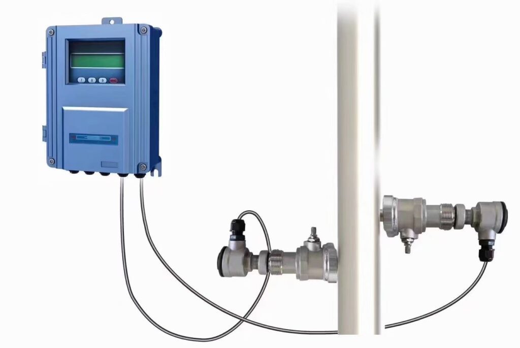
A clamp-on ultrasonic flow meter attaches piezoelectric transducers (devices that convert electrical signals to ultrasonic vibrations and back again) to the outside surface of an existing pipe using mounting rails or chains. No pipe penetration. No fluid contact. The transducers transmit ultrasonic pulses at frequencies between 0.5 and 4 MHz — far above human hearing — through the pipe wall and into the flowing fluid.
The dominant technology for clean liquid applications is transit-time measurement (also called time-of-flight). Two transducers are mounted on the same pipe, one upstream and one downstream. Each one alternately transmits and receives. When fluid is stationary, both pulses take the same time to travel the acoustic path. When fluid flows, the downstream pulse travels slightly faster (it moves with the fluid) and the upstream pulse travels slightly slower (it moves against it). The time difference — typically in the nanosecond range — is directly proportional to fluid velocity. Multiply velocity by the pipe’s cross-sectional area and you have volumetric flow rate.
For dirty fluids — wastewater with suspended solids, activated sludge, slurry — Doppler-shift measurement is used instead. The meter transmits a continuous ultrasonic beam into the fluid. Particles and bubbles moving with the fluid reflect the signal back at a slightly different frequency. That frequency shift is proportional to the particle velocity, and therefore to the fluid velocity. Doppler meters require a minimum solids or bubble content (typically >80 mg/L at particle sizes above 75 µm) to function; they will not work on clean, particle-free liquids.
The practical selection rule: clean liquid → transit-time. Dirty liquid with consistent particulate content → Doppler. Wrong choice means either no reading at all or severely degraded accuracy. This is the single most common misapplication error in the clamp-on segment, and it is entirely avoidable with a 30-second fluid characterisation question at the start of any specification conversation.
| Paramètre | Transit-Time Clamp-On | Doppler Clamp-On | Inline Multi-Path |
|---|---|---|---|
| Best For | Clean liquids (water, oil, chemicals) | Wastewater, slurry, aerated liquids | Fiscal metering, custody transfer |
| Précision typique | ±0.5–1.5% of reading | ±2–5% of reading | ±0.15–0.5% of reading |
| Rapport de réduction | 100:1–150:1 | 20:1–50:1 | Up to 400:1 |
| Pipe Contact Required | Non | Non | Yes (wetted transducers) |
| Process Shutdown for Install | Non | Non | Oui |
| Custody Transfer Certified | Non | Non | Yes (AGA-9, API MPMS 5.8) |
| 5-yr Maintenance Cost (DN100) | ~$1,700–$2,500 | ~$2,000–$3,000 | ~$6,300–$9,500 |
Modern clamp-on transmitters also include a Signal Quality Index (SQI) — a real-time 0–100% readout of received signal strength. An SQI above 60% confirms that the acoustic path through the pipe wall and fluid is adequate for reliable measurement. Below 50% means the location needs investigation: pipe wall condition, couplant quality, or transducer alignment. SQI is the field technician’s single most important tool for confirming installation quality before commissioning sign-off — and it takes 30 seconds to read.

▶ Watch on YouTube: How to Use and Install a Clamp-On Ultrasonic Flow Meter — step-by-step installation guide covering transducer placement, parameter configuration, acoustic couplant application, and signal quality verification.
Benefit 1: Rapid, Non-Invasive Installation — Minimize Downtime, Maximize Uptime

The most immediate financial argument for clamp-on meters is not instrument cost — it is installation cost. A trained instrument technician installs a clamp-on meter in 60–90 minutes on a known pipe, with no process interruption, no pipe cutting, no welding permit, and no pressure test. The total labour cost is $150–$400. Compare this to the equivalent inline installation in an operating plant:
| Cost Element | Clamp-On Installation | Inline (Spool-Piece) Retrofit |
|---|---|---|
| Instrument cost | $1 500 – $4 000 | $3,000–$8,000 |
| Installation labour | $150–$400 (1–2 hrs) | $1,200–$3,500 (4–8 hrs, multi-trade) |
| Pipe cutting & flanging | $0 | $600–$2,000 |
| Process shutdown cost | $0 | $2,000–$60,000+ (industry-dependent) |
| Pressure testing & sign-off | $0 | $200–$800 |
| Commissioning | $100–$300 | $300–$800 |
| Total Installed Cost | $1,750–$4,700 | $7,300–$75,000+ |
The shutdown cost range is wide because it depends entirely on what the process is worth per hour. A pharmaceutical batch reactor generating $25,000 per hour of output absorbs $200,000 in opportunity cost during an 8-hour installation window. A municipal pump station absorbs $1,000–$8,000 in the same period. Understanding the client’s production economics — not just the meter price — is what separates a commodity transaction from a value-based recommendation.
The downstream EPC benefit is equally concrete. An EPC firm managing a water treatment plant expansion in Southeast Asia specified clamp-on transit-time meters for 31 of its 40 measurement points — all of them monitoring-grade applications where ±1.5% accuracy was fully adequate. The remaining nine points, including the primary plant influent and treated water discharge meters, received inline multi-path meters for billing accuracy. Total project outcome: commissioning time for the clamp-on points was 40% faster than the equivalent inline commissioning sequence from a previous comparable project. The schedule saving on a $9 million contract was worth approximately $180,000 in avoided liquidated damage risk. The nine inline meters were installed during planned concrete curing breaks, bundling the shutdown windows into the construction schedule without creating additional critical-path delays.
For OEM skid builders, the benefit is different but equally real. A cooling water skid with eight flow measurement points — flow in, flow out, and six branch measurements — built with clamp-on meters instead of inline spool pieces eliminates eight flange pairs, eight pressure tests, and the pipe isometric revision required every time a measurement point needs to move. The build labour saving on a complex skid assembly is typically $3,000–$8,000 per unit, and the design flexibility gained — the ability to reposition a measurement point without modifying the pipe circuit — has value that does not appear in any cost column but is immediately recognisable to any skid builder who has had to revise a fabrication drawing at the 11th hour.
Benefit 2: Unmatched Accuracy and Repeatability Across Fluid Types
The word “unmatched” in this context requires a precise statement of scope. Clamp-on transit-time meters achieve ±0.5–1.5% of reading under real industrial field conditions — not laboratory catalogue conditions. Dual-path configurations (two acoustic chords rather than one) typically achieve ±0.5–1.0%. These are the specifications that matter for specification decisions, because real pipes are not perfectly round, real flow profiles are not perfectly developed, and real fluids are not perfectly homogeneous. An independent field study published in Mesure des débits et instrumentation (ScienceDirect) tested seven clamp-on transit-time meters under industrial conditions on well-characterised carbon steel and stainless steel pipe sections, and found best-case field accuracy of 1.0% for single-path and 0.6% for dual-path configurations — consistent with the specification when installation best practices were followed.
Where does ±1.0–1.5% matter, and where does it not? This is the question that determines whether a clamp-on meter is the right tool for a given measurement point.
Dans chemical processing, the standard accuracy requirement for process mass balance and raw material consumption tracking is ±1–2%. A DN150 line feeding a reactor with a daily throughput of 500,000 kg of raw material at $0.40/kg: a 1.5% measurement uncertainty represents ±$3,000 in daily inventory reconciliation ambiguity. For a facility already running a ±5% rotameter, upgrading to a 1.5% clamp-on meter reduces that ambiguity to ±$1,000 — a meaningful improvement that tightens procurement planning without requiring the ±0.3% accuracy that only Coriolis or multi-path inline meters can deliver.
A chemical plant in Jiangsu Province running six reactor feed lines on rotameters (±5% of reading) replaced them with PTFE-lined inline meters for critical dosing accuracy. But for the 14 utility and recirculation lines in the same facility, the engineering team specified clamp-on transit-time meters from Jade Ant Instruments. The outcome: total installed cost for the 14 clamp-on points was $38,000 versus an estimated $140,000 for equivalent inline installation — and the utility measurements, which had previously been estimated by rule-of-thumb, were now tracked to ±1.2%, sufficient for the ISO 50001 energy management programme the facility was implementing.
Dans HVAC and district energy, a DN300 chilled water header carrying 800 m³/hr at a 6°C supply/return temperature differential represents approximately 5.6 MW of cooling load. At a district cooling tariff of $0.08/kWh, a 2% metering error generates $78,000 per year in billing discrepancy. A dual-path clamp-on meter achieving 0.8% accuracy on a clean, well-characterised chilled water pipe reduces that billing uncertainty to $31,000 — and does so without any process shutdown or pipe modification. For building landlords and district energy operators, this is a straightforward financial calculation.
The critical point for distributors is this: accuracy is not a single number to be maximised regardless of application. It is a requirement to be matched. A measurement point where ±2% is operationally adequate should not receive a ±0.2% Coriolis meter — and it should not receive a clamp-on meter that cannot deliver better than ±3% on a corroded or rubber-lined pipe. The specification conversation begins with “what accuracy does this application actually require and what are the consequences of exceeding or not meeting that requirement?” — and clamp-on meters satisfy that requirement correctly for the majority of industrial monitoring, energy metering, and process control applications.
Accuracy Achievable Under Real Field Conditions

Dual-Path Clamp-On (clean pipe)     ██████████████████░░  ±0.5–1.0%
Single-Path Clamp-On (clean pipe)   █████████████░░░░░░░  ±1.0–1.5%
Inline Single-Path Ultrasonic       ████████████████░░░░  ±0.5–1.0%
Inline Multi-Path Ultrasonic        ██████████████████░░  ±0.15–0.5%
Turbine Meter (clean water)         ████████████░░░░░░░░  ±0.5–1.0%
Rotameter / Variable-Area           █████░░░░░░░░░░░░░░░  ±3–5%

Better accuracy = more filled blocks
Benefit 3: Drastically Lower Maintenance and Lifecycle Costs
No moving parts is not a marketing phrase — it is a maintenance schedule. Clamp-on ultrasonic meters have no bearings to replace, no impellers to balance, no seals to degrade, no electrode surfaces to corrode, and no internal surfaces to foul. The transducers clamp to the pipe exterior and transmit through the wall. The process fluid never contacts the instrument. The primary ongoing maintenance item is acoustic couplant — the gel or solid-state pad between the transducer face and the pipe surface that eliminates signal-blocking air gaps.
Standard silicone gel couplant in an outdoor or elevated-temperature installation degrades in 12–24 months and needs refreshing. A couplant inspection and refresh takes one technician 30 minutes and requires no process interruption. Solid-state coupling pads, available on premium models, last 5+ years without replacement. When a transducer eventually fails — typically after 100,000+ operating hours — replacement takes 20 minutes, requires no tools, no permit, no pipe isolation, and costs $200–$500 in parts.
Compare this five-year maintenance cost to a turbine meter in the same service:
| Maintenance Category | Clamp-On (5 yr, DN100) | Turbine Meter (5 yr, DN100) | Inline Ultrasonic (5 yr, DN100) |
|---|---|---|---|
| Scheduled calibration | $1,000 (2 field verifications) | $1,800 (annual lab recal) | $3,500 (lab recal + logistics) |
| Couplant / transducer maintenance | $300 (gel refresh ×2) | N/A | $800 (window inspection, cleaning) |
| Bearing / seal replacement | $0 | $2,400 (3 events) | $0 |
| Unplanned maintenance events | $400 (transducer swap, no downtime) | $1,800 (isolation + rebuild) | $2,000 (isolation + disassembly) |
| Labour hours (5 yr total) | 8–12 hrs | 28–40 hrs | 24–48 hrs |
| 5-Year Maintenance Total | $1,700–$2,500 | $6,000–$9,000 | $6,300–$9,500 |
The practical consequence of this difference was demonstrated by a municipal water utility managing 12 district pumping stations across a regional distribution network. The stations had been running turbine meters for billing verification and pump performance tracking, with a combined annual maintenance expenditure of $21,000 — bearing replacements, calibration events, and two unplanned service calls per year across the network. After retrofitting with clamp-on transit-time meters, first-year maintenance expenditure dropped to $3,200 — couplant refreshes across all 12 stations and one transducer replacement on a station exposed to direct sunlight. The $17,800 annual saving paid back the entire retrofit capital cost ($68,000 installed across all 12 stations) within four years, without including the operational value of having real-time pump efficiency data for the first time in the network’s history.
For MRO maintenance teams, the secondary benefit is equally important: inventory simplification. A clamp-on transducer pair for DN50–DN200 pipe is a standard stocked item worth $200–$500. A replacement turbine meter rotor assembly for a DN150 meter is an application-specific part with a 4–8 week lead time. The maintenance team that stocks one clamp-on spare transducer pair has contingency coverage for a dozen measurement points. The team relying on turbine meter spares maintains a parts inventory worth $8,000–$20,000 to cover the same number of points — and still faces the risk of a lead-time gap when an unusual size fails unexpectedly.
Benefit 4: Flexible Retrofit and Temporary Monitoring Capabilities

This is the benefit that creates the most revenue opportunities for distributors who recognise it — because it turns a clamp-on meter from a permanent installation product into a service-delivery platform.
A portable clamp-on kit covering DN25 to DN600 pipe diameters costs $4,000–$10,000 and can be deployed and relocated across 50+ measurement points in a single facility in days. That same kit functions as a commissioning verification tool (confirming that a newly installed inline meter is reading correctly), an energy audit instrument (mapping flow across an HVAC or compressed air system to identify inefficiencies), a leak detection aid (comparing inflow and outflow across a distribution zone to quantify unaccounted-for water), a temporary bypass measurement point (maintaining flow data during inline meter servicing), and a permanent installation if no subsequent permanent meter is needed.
The system integrator application is where this flexibility has the highest project value. An EPC firm was tasked with validating pump performance on 14 pumping units before a major refinery expansion commission. The specification called for flow measurement at each pump outlet to confirm flow rate, head, and efficiency against pump curves before final client handover. Installing permanent inline meters at all 14 points would have cost $140,000–$280,000 and required pipe modifications. Using a portable clamp-on kit, a two-person team completed all 14 measurements in three days, generated documented flow curves for the client handover package, and confirmed two pumps that were operating 12% below their rated performance curves — a finding that saved the client from commissioning underperforming assets into a $200 million expansion project. Total cost of the flow measurement programme: $7,500 for the portable kit rental and three days of technician time.
The retrofit application for MRO teams follows the same logic but across a longer time horizon. A steel mill managing 22 cooling water measurement points had been replacing differential pressure transmitters and orifice plates on a rolling schedule as they failed. After a trial with clamp-on meters on six points, the maintenance team found that clamp-on accuracy was adequate for their cooling water mass balance requirements (±2% tolerance), installation took a fraction of the time, and the meters provided SQI diagnostics that gave early warning of couplant degradation rather than silent reading drift. The remaining 16 points were retrofitted over the following 12 months, using each orifice plate failure event as an opportunity to switch to clamp-on rather than replacing like-for-like.
The NRW reduction application for water utilities is where temporary monitoring creates the most verifiable financial return. A district metered area (DMA) supplying 15,000 households is suspected of having significant unaccounted-for water — the total flow entering the zone exceeds metered consumption by 18%. A temporary clamp-on monitoring campaign across the DMA’s six inlet and eight major sub-zone measurement points, run for 30 days, generates enough data to pinpoint the zones with the highest apparent loss. The subsequent pipe rehabilitation investment targets those zones specifically rather than requiring a blanket network survey — a saving of $200,000–$600,000 in survey cost on a typical urban network. According to McRometer’s non-revenue water guidance, utilities that implement systematic district metering consistently reduce NRW by 15–30% — recoverable revenue that in a 500,000-connection water system can represent $2–8 million per year.
Benefit 5: Enhanced Process Control and Data Integration for Smart Operations
The data connectivity of modern clamp-on meters is no longer a differentiator — it is a baseline expectation. Every serious industrial-grade clamp-on transmitter supports 4–20 mA analog output (compatible with every PLC, DCS, and SCADA input card manufactured in the last 40 years), pulse/frequency output for totaliser-based batch and billing applications, and digital communication protocols for full integration into plant automation infrastructure. The question is which digital protocol matches the client’s environment.
Modbus RTU over RS-485 is supported by virtually all modern industrial control platforms — Siemens S7, Allen-Bradley ControlLogix, ABB 800xA, Honeywell Experion, Yokogawa CENTUM — and allows a single cable pair to carry flow rate, velocity, temperature, SQI, totalised volume, and alarm status from multiple meters to a SCADA historian. Modbus TCP over Ethernet extends this to cloud analytics platforms and remote monitoring portals without a protocol gateway. HART (Highway Addressable Remote Transducer — a protocol that superimposes digital signals on a standard 4–20 mA loop) enables remote configuration, diagnostics, and secondary variable transmission without additional wiring, making it the standard for facilities that have existing HART infrastructure. Premium models add PROFIBUS PA for DCS-centric European process plants, and the most recent generation includes OPC-UA over Ethernet APL — the architecture that feeds digital twin models and AI-based predictive maintenance platforms.
| Communication Protocol | Physical Layer | Best For |
|---|---|---|
| 4–20 mA Analog | Two-wire | Universal — any PLC, DCS, or SCADA input |
| Pulse/Frequency | Two-wire | Totaliser-based billing and batch control |
| HART 7 | Overlay on 4–20 mA | Remote diagnostics, multi-variable, existing HART infra |
| Modbus RTU | RS-485 | Multi-drop SCADA, low-cost integration |
| Modbus TCP | Ethernet | Cloud analytics, remote monitoring portals |
| PROFIBUS PA | Two-wire IS | DCS-centric plants (Siemens, ABB, Honeywell) |
| OPC-UA / Ethernet APL | Two-wire Ethernet | Digital twin, AI predictive maintenance, new plants |
The OEM skid builder application illustrates what this connectivity delivers in practice. A manufacturer of cooling water skids for data centre clients integrated clamp-on meters with Modbus TCP output into six branch measurement points on each skid. The transmitters feed real-time flow data — flow rate, velocity, totalised volume, and temperature — directly into the skid’s onboard PLC, which calculates cooling load per server rack and generates an alarm when any branch drops below its design flow rate. The client can monitor all skids remotely via a cloud dashboard. Before this integration, cooling flow was verified manually during quarterly maintenance visits. After integration, the first-year operating data identified three skids where flow imbalance across branches was causing localised hot spots in the data hall — a finding that allowed targeted cooling infrastructure adjustment before any server hardware was affected. The client renewed their skid supply contract for a further 24 units, specifying the same integrated monitoring configuration. Jade Ant Instruments supports this type of OEM integration with configurable Modbus register maps, OEM-branded transmitter faceplates, and application engineering support for protocol-specific commissioning.
The broader Industry 4.0 relevance is straightforward. Corporate sustainability commitments, ISO 50001 energy management certification, and the EU Carbon Border Adjustment Mechanism (CBAM) are all driving industrial facilities to measure more energy and process flows — continuously, reliably, and with documented accuracy. Clamp-on meters are the only technology that can deploy this expanded measurement infrastructure across a brownfield plant without process disruption. Every corporate energy manager who cannot currently quantify their facility’s cooling water consumption, compressed air distribution loss, or thermal energy balance is a potential client for a clamp-on monitoring programme. Understanding this connection between measurement technology and ESG compliance reporting is what positions a distributor as a strategic partner rather than a product supplier. For more on how flow meter communication protocols integrate with industrial automation systems, the Turbines Incorporated protocol guide provides a useful reference across 4–20 mA, Modbus, HART, and wireless standards.
Industry-Specific Applications and ROI Scenarios

The financial return from clamp-on meters differs in detail by segment, but the structure of the argument is consistent: lower installed cost, lower lifecycle cost, faster deployment, and adequate accuracy for the majority of measurement points in any facility.
Pour OEM and skid-mount manufacturers, the primary value is in build cost reduction and product differentiation. A skid builder who eliminates eight inline spool pieces from a cooling water skid design — replacing them with clamp-on external sensors — saves $12,000–$25,000 in fabrication labour and removes pipe isometric revision from the design change process. More importantly, the skid ships without any measurement-related commissioning delays: clamp-on sensors are installed and verified in hours, not days. OEMs who add real-time flow monitoring with Modbus TCP connectivity as a standard feature — rather than an expensive option — are differentiating on capability rather than competing on price.
Pour instrument distributors and importers, the commercial proposition has two layers. The first is margin: clamp-on meters on a per-unit basis typically carry higher gross margin than commodity mechanical meters, because the value proposition (zero shutdown, rapid install, long service life) supports the price. The second is post-sale simplicity: a clamp-on meter sold into a municipal application may generate zero after-sale service activity for five years. A turbine meter in the same application generates 2–4 service events per year at $350–$800 in distributor labour and parts per event. The low-maintenance product is the higher-value product in a distributor’s total account economics — it frees capacity for new business development instead of servicing problem accounts.
Pour EPC and system integrators, the schedule compression argument is the strongest. On a project with 30 monitoring-grade measurement points, switching from inline to clamp-on saves 6–12 weeks of procurement lead time and 3–5 days of installation labour. On a performance contract where schedule delays trigger liquidated damages, those savings are directly bankable. For the nine or ten points in the same project that genuinely require inline multi-path accuracy — fiscal meters, regulatory compliance points — inline remains the correct specification. The skill is in correctly segmenting the two categories, not in defaulting to one technology across all points.
Pour industrial MRO and terminal operations, the maintenance elimination argument is the primary driver. The steel mill example from Benefit 3 ($47,000 saved over three years across 12 measurement points) represents a typical outcome for facilities running mechanical meters in moderate to aggressive service. The MRO team’s additional benefit — predictive maintenance enabled by SQI trend monitoring — converts reactive maintenance scheduling into condition-based maintenance, reducing total maintenance hours by 25–35% for the metered circuit.
Pour municipal and utility companies, the NRW reduction mathematics are the most compelling. A water authority supplying 80,000 connections with an estimated 22% NRW rate is losing approximately 1.6 billion litres per year in unaccounted water. At a production cost of $0.35 per cubic metre, that is $560,000 in annual production cost absorbed without any corresponding revenue. A clamp-on district metering programme across 40 DMA inlets, installed at $3,500 per point ($140,000 total), that identifies and enables repair of 30% of the loss — recoverable volume: 480 million litres — generates $168,000 in recovered production cost annually, paying back the metering investment in under 10 months. For a billing rate of $0.90 per cubic metre, the recovered revenue is $432,000 annually. These are the numbers that get NRW programmes approved at budget committees — and they are built on the affordability of clamp-on measurement, not on the accuracy of inline metering. According to Badger Meter’s non-revenue water analysis, utilities implementing systematic ultrasonic metering programmes consistently achieve 15–30% NRW reductions in the first 18 months.
| Segment de clientèle | Principal facteur de retour sur investissement | Illustrative 5-Year Value per Point |
|---|---|---|
| OEM / Skid Manufacturers | Build cost reduction + product differentiation | $3,000–$10,000 |
| Distributors / Importers | Higher margin + reduced post-sale service burden | $1 500 – $4 000 |
| EPC / System Integrators | Schedule compression + commissioning speed | $2,000–$8,000 |
| Industrial MRO | Maintenance elimination + uptime recovery | $3,500–$12,000 |
| Collectivités locales / Services publics | NRW reduction + billing accuracy | $5,000–$35,000+ |
Where Clamp-On Meters Are Not the Right Answer
An honest guide to clamp-on technology has to include a clear statement of its limits — because a mis-specified meter creates more damage to a client relationship than no meter at all.
Clamp-on meters are not suitable for fiscal custody transfer of oil, gas, or water between trading parties. API MPMS Chapter 5.8 (liquid hydrocarbons) and AGA Report No. 9 (natural gas) require inline multi-path meters with NIST-traceable wet-flow calibration and documented uncertainty budgets below 0.25%. No clamp-on configuration currently meets these standards for legal custody transfer. If a client application involves billing between two legal entities, an inline meter is the correct specification — and recommending otherwise creates liability.
Clamp-on transit-time meters are not suitable for rubber-lined, bitumen-lined, or concrete-lined pipes, where an air gap between the liner and the steel pipe wall causes near-total acoustic reflection, preventing the ultrasonic signal from penetrating the fluid. A field SQI check before committing to a specification resolves this in 30 minutes — but skipping that check and assuming compatibility on a lined pipe is the fastest way to generate a warranty dispute. Jade Ant Instruments’ clamp-on selection guide includes a pipe compatibility checklist covering all common lining types and their acoustic transmission characteristics.
Clamp-on meters are also not suitable for highly aerated or gas-entrained liquids using transit-time technology — bubbles scatter the ultrasonic signal and cause signal loss. If the application involves CIP foam stages, cavitating pump discharge, or flash-boiling condensate return, a Doppler meter or an inline technology is more appropriate.
These are not weaknesses of the technology — they are boundaries. Understanding them, communicating them clearly, and offering the right alternative for out-of-scope applications is what builds credibility with engineering clients who will test your technical knowledge before they place a significant purchase order.
How to Implement Clamp-On Flow Technology in Your Projects
The implementation process begins with a site survey, and the site survey begins with pipe measurement — not a data sheet lookup. Pipe outside diameter (OD), wall thickness, material, and lining condition must be confirmed by physical measurement, not inferred from nominal pipe size tables. A 1 mm OD error on a DN100 pipe introduces approximately 2% velocity offset into every reading from that meter, permanently and silently. A wall thickness taken from a schedule table rather than an ultrasonic thickness gauge measurement may be 15–20% different from the actual worn condition of an ageing pipe — and that difference shifts the acoustic path geometry in ways the meter cannot self-correct.
The five pieces of site information that determine whether a clamp-on installation will succeed are: pipe OD (measured), wall thickness (measured at 3–4 circumferential points), pipe material and any lining, fluid type and temperature, and available straight-run upstream and downstream of the intended measurement location. Minimum straight-run recommendation is 10D upstream and 5D downstream of any flow disturbance — elbow, valve, pump, or reducer. Short straight-run situations are not always disqualifying, but they require a different transducer mounting configuration (Z-mode instead of V-mode on small pipes, increased transducer spacing, or dual-path to compensate for profile asymmetry) and must be explicitly addressed in the specification.
After installation, the 30-day and 90-day performance check is not a troubleshooting exercise — it is a client relationship investment. An SQI reading taken 30 days after installation, compared to the commissioning SQI, tells you whether couplant is stable. A flow profile comparison against the commissioning baseline tells you whether operating conditions have changed. These data points take 20 minutes to collect and document — and the documented evidence that the meter is reading correctly 90 days after installation is the most persuasive technical support tool for the client’s second project with you.
For distributors building a clamp-on product capability from scratch, the sequence that works is: stock a portable audit kit first (one kit covers all pipe sizes during the sales process and client demonstrations), then build fixed-installation stock in the two or three pipe size ranges most common in your key vertical markets, then develop a rental programme for temporary monitoring applications (energy audits, commissioning verification, NRW surveys) that generates both direct revenue and a pipeline of permanent installation projects from clients who experience the technology before committing to it. Jade Ant Instruments supports distributor partners with product range, technical documentation, and application engineering — including free pre-sale compatibility assessments and pipe-specific transducer spacing calculations for any application where the right specification is not immediately clear.
For reference, the Emerson magnetic flow meter technical resources et Endress+Hauser ultrasonic flowmeter documentation provide authoritative technical background on flow measurement principles applicable across both inline and clamp-on technologies — useful references for distributor technical training programmes.
Terminology Glossary
Transit-Time (Time-of-Flight): The ultrasonic measurement principle that calculates fluid velocity from the difference in travel time between upstream and downstream pulses. Requires clean, particle-free fluid. Achieves ±0.5–1.5% accuracy on well-installed systems. Used for: water, clean chemicals, oils, HVAC fluids, food-grade liquids.
Doppler-Shift: The ultrasonic measurement principle that measures the frequency shift of signals reflected from particles or bubbles in the fluid. Requires consistent particulate or bubble content (>80 mg/L). Accuracy: ±2–5%. Used for: wastewater, slurry, aerated process fluids.
Signal Quality Index (SQI): A real-time 0–100% indicator of received ultrasonic signal strength. Above 60%: reliable measurement. Below 50%: investigate pipe condition, couplant, and transducer alignment. The primary field commissioning quality indicator.
Turndown Ratio: The ratio of maximum to minimum measurable flow rate at which the meter maintains its specified accuracy. A 100:1 turndown on a meter rated to 10 m/s means reliable measurement down to 0.1 m/s. Clamp-on transit-time meters typically achieve 100:1–150:1.
Non-Revenue Water (NRW): Water produced by a utility that is not billed to customers — lost to leakage, meter errors, or unauthorised consumption. Global average: 30–40% in developing markets. Clamp-on meters on District Metered Area (DMA) inlets are the primary measurement tool for NRW reduction programmes.
V-Mode / Z-Mode: The two mounting geometries for clamp-on transducers. V-mode (both transducers on the same side of the pipe, signal bounces off the opposite wall) is used on smaller pipes (DN25–DN300). Z-mode (transducers on opposite sides of the pipe, signal crosses directly) is used on larger pipes (DN200+) where signal attenuation makes the V-mode bounce path impractical.
Acoustic Couplant: The gel or solid-state compound applied between the transducer face and the pipe surface to eliminate air gaps that would block ultrasonic signal transmission. Standard gel requires replacement every 12–24 months in outdoor or high-temperature applications. Solid-state pads last 5+ years.
HART (Highway Addressable Remote Transducer) : A communication protocol that superimposes a 1.2 kbps digital signal on the standard 4–20 mA loop, enabling two-way communication — remote configuration, diagnostics, and multi-variable reading — without additional wiring.
DMA (District Metered Area): A defined zone within a water distribution network, isolated by closed boundary valves, with all inflows and outflows metered. The fundamental unit of NRW management — mass balance across a DMA quantifies apparent loss and directs leak repair effort.
ISO 50001: The international standard for energy management systems. Requires continuous measurement of significant energy flows, including thermal energy in heating/cooling systems. Clamp-on meters are the primary tool for building ISO 50001-compliant sub-metering infrastructure without process disruption.
Clamp-on ultrasonic flow meters are not the right answer for every measurement point. They are, however, the right answer for the majority of monitoring-grade, retrofit, and energy metering applications across every industry segment your clients operate in — and they deliver that answer at 60–80% lower total installed cost than the inline alternatives they replace.
The conversation that wins the specification is not “our meter is better.” It is “let’s look at what this measurement point actually requires in terms of accuracy, what it will cost to install in your environment, and what it will cost to maintain over the next five years — and then make the recommendation that makes the best financial sense for your operation.”
Explore the full Jade Ant Instruments ultrasonic clamp-on flow meter range →
Read the inline vs. clamp-on cost comparison guide for distributors →
Access the clamp-on flow meter industrial applications guide →
Learn how to choose the right flow meter — 5 factors for 2026 →
Contact the Jade Ant Instruments engineering team for a free application assessment →
Questions fréquemment posées
How accurate are ultrasonic clamp-on flow meters compared to inline meters? Under real industrial field conditions — not laboratory catalogues — single-path clamp-on transit-time meters achieve ±1.0–1.5% of reading; dual-path models achieve ±0.5–1.0%. Inline single-path meters achieve ±0.5–1.0%; inline multi-path meters achieve ±0.15–0.5%. For the majority of monitoring, HVAC metering, and process control applications, ±1.0–1.5% is fully adequate. For fiscal custody transfer and regulatory-mandated accuracy applications, inline multi-path remains the only appropriate technology. The key question is always what the specific application requires — not which technology achieves the highest possible number.
Can clamp-on meters work on coated or insulated pipes? They can work on externally insulated pipes if the insulation is removed at the measurement location to allow transducer contact with the bare pipe surface. For internally rubber-lined, bitumen-coated, or concrete-lined pipes, the air gap between the liner and the steel wall creates near-total acoustic reflection that prevents the ultrasonic signal from reaching the fluid. A field Signal Quality Index (SQI) check at the intended measurement location, before committing to the specification, definitively confirms whether a borderline pipe will work — and takes 30 minutes.
Do I need to cut the pipe or stop the process to install them? No. Clamp-on meters install on the outside of the existing pipe with no pipe penetration, no welding, no process shutdown, and no pressure test. A trained technician completes installation in 60–90 minutes. The process runs at full capacity throughout. This is the technology’s most commercially important characteristic: it transforms flow measurement from a capital project requiring a planned shutdown into a routine instrumentation task completable during normal operations.
What pipe materials and sizes are compatible? Compatible materials include carbon steel, stainless steel (304, 316, duplex), copper, brass, PVC, CPVC, HDPE, PP, and PVDF. Standard clamp-on configurations cover DN25 to DN3000 (approximately ½” to 120″). Incompatible conditions include internal rubber lining, bitumen lining, concrete lining, and severely corroded pipe with greater than 15% wall thickness variation from nominal. When in doubt, a field SQI test confirms compatibility before any purchase decision is made.
How do air bubbles or solids in the liquid affect transit-time measurement? Suspended bubbles scatter ultrasonic signals and degrade transit-time meter accuracy proportionally to bubble concentration. Above approximately 2–3% gas void fraction, signal loss becomes severe enough to cause dropouts or erroneous readings. For aerated liquids, Doppler-mode measurement is the appropriate technology — it requires particles or bubbles as reflectors. For fluids with consistent solids content above 80 mg/L at particle sizes above 75 µm, a Doppler clamp-on meter is specified. The selection choice between transit-time and Doppler is determined by fluid characterisation, not by preference.
Are clamp-on meters suitable for custody transfer applications? No. Clamp-on meters are used for process monitoring, energy metering, and operational control — not fiscal custody transfer between legal trading parties. Custody transfer of oil, gas, or water requires inline multi-path meters meeting API MPMS Chapter 5.8, AGA Report No. 9, or equivalent national standards, with NIST-traceable wet-flow calibration documentation and certified uncertainty budgets below 0.25%. Any specification that involves billing between two entities should default to a certified inline meter, regardless of cost.
What is the typical lifespan of a clamp-on flow meter? The transmitter electronics typically operate for 10–15+ years without scheduled replacement. Transducers, protected in IP67 or IP68 enclosures and never contacting the process fluid, have a mean time between failures (MTBF) exceeding 100,000 hours — over 11 years of continuous operation. The only consumable element is acoustic couplant, which requires inspection and refresh every 12–24 months for gel types, or every 5+ years for solid-state coupling pads. No bearings, no seals, no impellers, and no wetted surfaces mean there is no wear mechanism driving replacement cycles.
Can they measure bidirectional flow? Yes — bidirectional measurement is standard on all industrial-grade transit-time clamp-on meters. When flow reverses, the meter automatically detects the reversal, displays the reversed velocity as a negative value, and accumulates the reverse total in a separate register. No additional hardware is required. This is particularly relevant for CIP (Clean-in-Place) loops in food and pharmaceutical applications, district cooling return circuits, and distribution networks where valve switching generates reverse flow transients.
How often do clamp-on meters need calibration? In stable industrial monitoring applications, clamp-on transit-time meters are effectively calibration-free for 5+ years — the measurement is derived from acoustic time-of-flight physics, not a mechanical interaction that wears or drifts. Periodic field verification — comparing the meter reading against a portable reference meter or a known flow condition — is recommended every 1–3 years for quality management documentation purposes. This field verification takes 2–4 hours and does not require removing the meter from service. Regulated or fiscal applications with defined calibration intervals follow those intervals regardless of technology.
Do they work on non-conductive fluids like oils or chemicals? Yes — this is one of the key advantages of ultrasonic technology over electromagnetic (magnetic) flow meters. Ultrasonic measurement does not require electrical conductivity in the fluid. Transit-time clamp-on meters work on hydrocarbons (diesel, fuel oil, crude oil), solvents (acetone, methanol, xylene), glycols, lubricating oils, and even cryogenic liquids (liquid nitrogen, LNG) — provided the fluid is clean, particle-free, and does not contain significant entrained gas. This makes clamp-on ultrasonic meters the only non-invasive option for petroleum product distribution, solvent processing, and clean hydrocarbon monitoring applications.
Can I integrate the output with my PLC or SCADA system? Yes. Every industrial-grade clamp-on transmitter provides at minimum a standard 4–20 mA analog output and pulse output, compatible with every PLC, DCS, and SCADA input card manufactured in the last 40 years. Digital protocols — Modbus RTU (RS-485), Modbus TCP (Ethernet), and HART — are standard or optional on most current-generation models. These protocols carry not just flow rate but also velocity, temperature (where sensors are fitted), totalised volume, SQI diagnostic value, and alarm status — providing a complete data package for integration into process historians, energy management systems, and cloud analytics platforms. Protocol-specific register maps and integration support are available from Jade Ant Instruments for all major PLC and DCS platforms.
What support is available for installation and setup? Application engineering support for site surveys, pipe compatibility assessment, transducer spacing calculations, and SQI interpretation is available pre-sale — before any purchase commitment. Post-sale support includes commissioning documentation templates, mounting hardware kits, signal verification procedures, and remote commissioning assistance via video call for distributors and integrators working with unfamiliar pipe configurations. On-site training for instrument technicians covers pipe measurement technique, transducer mounting, couplant application, and SQI-based quality verification — the four skills that determine whether a clamp-on installation delivers specified accuracy or underperforms in the field.
Sources and further reading:
- Clamp-On Ultrasonic Flow Meters: The Non-Invasive Guide — Jade Ant Instruments
- Inline vs. Clamp-On Ultrasonic Flow Meter Cost Guide — Jade Ant Instruments
- Flow Meter Communication Protocols Explained — Turbines Incorporated
- Using Flow Meters to Reduce Non-Revenue Water — McCrometer
- Ultrasonic Clamp-On Meters in Water and Wastewater — Badger Meter
- Flow Measurement and Instrumentation Journal — ScienceDirect
- Ultrasonic Flow Meter Market — Fortune Business Insights