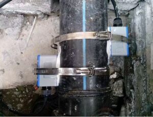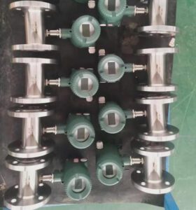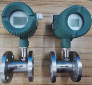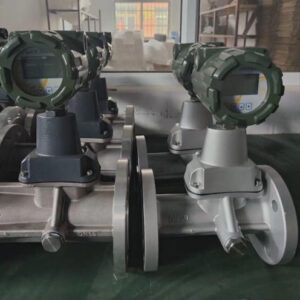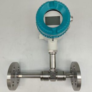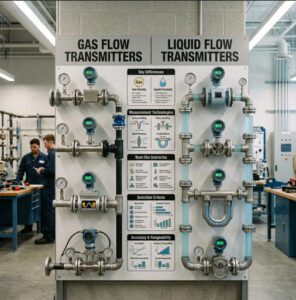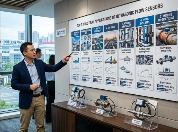
Sound waves measured in fractions of a microsecond. Sensors that never touch the liquid they measure. Flow data delivered in real time to SCADA systems running entire production facilities. Ultrasonic flow sensors have moved from a specialized niche to a mainstream industrial measurement technology — and for good reason. From a pharmaceutical CIP line in Switzerland to a crude oil transfer header in the Gulf of Mexico, the same core technology delivers non-contact, maintenance-light measurement across applications that once demanded half a dozen different instrument types. This article covers the top 7 industrial applications of ultrasonic flow sensors, with field data, industry benchmarks, and practical selection guidance for each.

Modern industrial facilities rely on ultrasonic flow sensors across diverse process streams — the same non-contact measurement principle serves chemical plants, water utilities, food factories, and oil platforms alike.
What Makes Ultrasonic Flow Sensors Different?
An ultrasonic flow sensor measures fluid velocity by analyzing high-frequency sound waves transmitted through the pipe and fluid. Unlike turbine meters that spin a rotor, or electromagnetic meters that require conductivity, ultrasonic sensors work through the pipe wall or in-line with no mechanical contact with the fluid in clamp-on configurations — and with no moving parts at all.
Two operating modes cover the full fluid spectrum. Transit-time sensors (for clean liquids) measure the difference in travel time between pulses sent upstream and downstream — a time gap directly proportional to velocity. Doppler sensors (for dirty or aerated fluids) measure the frequency shift of signals reflected off suspended particles or bubbles. Together, these two modes make ultrasonic technology applicable across a wider fluid range than almost any other single measurement principle.
The ultrasonic flow meter market was valued at approximately USD 3.9 billion in 2025 (Market Research Future) and is projected to grow at a CAGR of 6.3–7.5% through 2031, driven by expanding industrial automation, tighter energy management requirements, and the adoption of Industry 4.0 digital platforms that depend on reliable, continuous flow data.
Key Terms Defined
Watch: How Ultrasonic Flow Meters Work — Principles and Industrial Applications
▶ RealPars explains the transit-time and Doppler principles, transducer configurations, and industrial application context in clear visual detail — recommended viewing before diving into specific applications.
Why Ultrasonic Sensors Outperform Traditional Technologies in Industrial Settings
| Advantage | Practical Implication | Compared To |
|---|---|---|
| No moving parts | Zero mechanical wear; MTBF of 15–20+ years in continuous service | Turbine meters: bearings need replacement every 1–2 years on demanding service |
| Non-contact option (clamp-on) | No pipe penetration; installs on corrosive, toxic, or ultra-high-purity lines without safety risk | All inline meter types require pipe cutting and process isolation |
| Zero pressure drop (clamp-on) | No pumping energy penalty; significant cost savings on large-bore, high-flow lines | Orifice plates: 0.5–2 bar permanent pressure loss typical |
| Wide pipe size range | DN 10 to DN 6,000+ with clamp-on; single technology covers from lab tubing to large-bore headers | Most inline technologies top out at DN 300–600 affordably |
| Retrofit without shutdown | Clamp-on sensors install on operating pipes — no production interruption, no hot-work permit | All inline meters require process isolation and pipe modification |
| Works on non-conductive fluids | Measures hydrocarbons, pure water, solvents, cryogenic liquids — fluids electromagnetic meters cannot handle | Electromagnetic meters require ≥5 µS/cm conductivity |
| Source: Compiled from manufacturer technical specifications and field benchmark data. See Jade Ant Instruments’ ultrasonic vs. magnetic vs. turbine comparison guide for detailed technology benchmarks. | ||
1. Process Flow Monitoring in Chemical and Petrochemical Plants

In chemical and petrochemical plants, a 2% flow measurement error on a reactor feed line doesn’t just produce off-spec product — it can trigger thermal runaway events costing USD 50,000+ per hour in lost production. Ultrasonic sensors eliminate that risk on corrosive streams where other technologies fail.
Real-Time Flow Verification for Product Quality and Yield
In chemical manufacturing, the flow meter doesn’t just measure — it governs. Reactor feed ratios, blending concentrations, and residence time calculations all flow from accurate, real-time flow data. A phosphoric acid producer in Florida documented that switching from turbine meters to clamp-on ultrasonic sensors on their 8-inch product headers eliminated bearing failures that had previously been occurring every 4–6 months, reducing annual metering maintenance costs on those lines by 78% while maintaining ±1.5% accuracy — sufficient for their closed-loop process control application.
Transit-time ultrasonic sensors deliver ±0.5–1.0% accuracy on clean petrochemical streams — hydrocarbons, refined products, clean solvents — with no mechanical components in the fluid path. For multi-product lines that alternate between different chemicals (a common configuration in toll manufacturing and specialty chemical plants), the transit-time meter adapts to each fluid’s acoustic properties without mechanical reconfiguration. One contract chemical manufacturer runs the same ultrasonic meter on a shared transfer line that alternately carries ethylene glycol, methanol, and deionized water — a versatility that would require three different turbine meters to replicate.
Non-Contact Measurement for Corrosive or Hot Liquids
The clamp-on advantage is most decisive in chemical service. Concentrated sulfuric acid, hydrofluoric acid, fuming nitric acid, and chlorinated solvents — fluids that attack every wetted material from carbon steel to many grades of Hastelloy — are measured from outside the pipe, with transducers that never contact the process. This eliminates the materials compatibility engineering challenge entirely: if the existing pipe material survives the fluid (as it must regardless of meter choice), the clamp-on sensor works.
For high-temperature streams above 150°C — common in distillation column overhead lines and reactor product coolers — specialized high-temperature clamp-on transducers rated to +200°C are available. The Jade Ant Instruments guide on ultrasonic vs. turbine meters in chemical plants documents the total cost implications of this non-contact advantage across different corrosive service categories.
Integration with SCADA/DCS for Closed-Loop Control
Modern ultrasonic flow sensors output 4–20 mA analog signals, HART digital communication, PROFIBUS PA, FOUNDATION Fieldbus, Modbus RTU, and increasingly EtherNet/IP — covering every DCS and SCADA protocol in common use across petrochemical facilities. The flow signal feeds directly into flow controllers (FICs), ratio controllers for blending applications, and safety instrumented functions (SIFs) where the meter must respond within defined time windows.
For closed-loop control applications, the meter’s response time matters as much as steady-state accuracy. Transit-time ultrasonic sensors typically update at 1–10 Hz — adequate for most flow control loops. For fast-response applications like compressor anti-surge control, multipath ultrasonic meters updating at 50+ Hz are available but at significantly higher cost. Industry practice is to match update rate to the dynamics of the control loop, not to specify the fastest available meter as a default.
2. Water and Wastewater Management

Water utilities that have deployed permanent transit-time ultrasonic sensors at distribution network junction points consistently report leak detection rates of 15–25% faster than systems relying on periodic manual measurements — translating directly into recovered revenue and reduced non-revenue water.
Accurate Bleed-Off and Dosing for Treatment Chemicals
Water treatment plants consume significant volumes of coagulants, flocculants, disinfectants, and pH adjustment chemicals. Dosing these chemicals in the correct proportion to the actual water flow — not a fixed timed dose — requires accurate, continuous flow measurement. A municipal water authority in the UK documented that switching from time-based to flow-proportional chemical dosing (triggered by ultrasonic flow sensor readings) reduced coagulant consumption by 19% while maintaining treated water turbidity well within the 1 NTU regulatory limit. The annual chemical cost saving on a 50 MLD (megalitres per day) plant exceeded £120,000.
For bleed-off control in cooling towers — where the ratio of bleed-off flow to make-up flow determines water chemistry and scale/corrosion risk — clamp-on transit-time sensors on both the make-up and bleed-off lines provide the conductivity-ratio information that drives automated bleed-off valves. This is an application where the sensor never contacts aggressive cooling tower chemistry, and where the retrofit installation (no shutdown, no pipe modification) pays back its cost within weeks in chemical savings.
Continuous Custody Transfer in Water Distribution
Water distribution networks transfer treated water between utilities, between a utility and large industrial customers, and across municipal boundaries — all transactions requiring legally traceable, accurate measurement. Transit-time ultrasonic meters in inline (spool-piece) configuration deliver ±0.5% accuracy and are certified under OIML R 049 (water meters) for fiscal use in many jurisdictions.
Compared to traditional mechanical water meters (piston, turbine, or Woltman types), inline ultrasonic meters have no moving parts that wear with flow rate — mechanical meters in high-velocity service can drift by 2–4% per year as bearings and gears wear, a drift that directly translates to billing errors in multi-million litre daily transfers. For a water utility billing a large industrial customer at USD 0.50 per m³ with 100,000 m³/day flow, a 2% metering error represents USD 365,000 per year in under-billing — a payback calculation that justifies ultrasonic meter investment within 30–60 days in many large-distribution applications.
Wastewater: Doppler Sensors for Sludge and Aerated Streams
Wastewater influent, effluent, return activated sludge (RAS), and waste activated sludge (WAS) lines all contain suspended solids, biological flocs, and entrained air — exactly the conditions that make Doppler ultrasonic sensors the preferred measurement technology. Transit-time meters fail on these streams; Doppler meters thrive. Combined with the non-contact clamp-on installation that avoids fouling-prone wetted components, Doppler sensors in wastewater service consistently outperform electromagnetic meters in large-diameter sewer lines where the cost of installing full-bore wetted meters is prohibitive.
3. Food and Beverage Processing

Food and beverage processors face a measurement challenge that most other industries don’t: the flow meter must be accurate enough to govern recipe ratios, hygienic enough to satisfy food safety auditors, and robust enough to survive 140°C CIP cycles — multiple times per shift.
Hygienic Design and Cleanability Considerations
3-A Sanitary Standards and EHEDG certification require that any component contacting food products must have a smooth, crevice-free internal surface (Ra ≤0.8 µm), no dead-legs where product can accumulate, and materials approved for food contact under EU Regulation 10/2011 or FDA 21 CFR.
For inline ultrasonic meters in food service, this means electropolished stainless steel (316L) wetted surfaces, tri-clamp or hygienic flange connections, and no O-ring or seal materials that could harbor bacteria. The advantage over electromagnetic meters in food service is that ultrasonic transit-time technology works on non-conductive food products — fruit juices, oils, carbonated beverages, and beer — where electromagnetic meters require minimum 5 µS/cm conductivity that many food-grade liquids don’t provide.
Monitoring of Paste, Sauce, and Dairy Streams
Viscous food products — tomato paste (viscosity up to 10,000 cP), yogurt, cream, chocolate, and certain sauces — present measurement challenges that eliminate turbine meters (bearing wear) and create difficulties for transit-time ultrasonic sensors at high viscosity. For these streams, Doppler ultrasonic sensors are often the better choice: the micro-particles and air incorporated during mixing and pumping provide the acoustic reflectors needed, and the non-invasive clamp-on installation avoids the sanitary-design challenges of in-line wetted components.
A dairy cooperative in Germany documented Doppler clamp-on sensor deployments on their yogurt and cream lines: the measurement accuracy of ±3% was sufficient for recipe batch control and inventory accounting, while the clamp-on installation eliminated the dead-leg risk that had caused recurring bacterial contamination events with their previous turbine meters — reducing product recall risk with a single instrument change.
Compliance with Sanitary Standards and Traceability
Food safety regulations — EU 852/2004, FDA FSMA, and industry schemes like BRCGS Food Safety — require documented calibration traceability for measurement instruments that affect product safety or conformity. Inline ultrasonic meters in hygienic service carry calibration certificates traceable to national standards (PTB, NEL, NIST) and provide documented measurement uncertainty — the evidence basis needed for supplier audits and regulatory inspections.
Clamp-on sensors on clean product lines can be calibrated in-situ using a portable reference meter or by gravimetric comparison during a production run — a verification approach that meets most food industry audit requirements without removing the meter from service.
4. Pharmaceutical Manufacturing

In pharmaceutical manufacturing, a flow meter isn’t just a process instrument — it is a GMP-critical measurement device whose calibration records, material certificates, and qualification documentation will be reviewed by FDA and EMA inspectors.
Sterile and Clean-In-Place (CIP) Compatible Installations
Pharmaceutical manufacturing operates under cGMP (current Good Manufacturing Practices) that impose design requirements on every instrument in contact with product or product-contact water. For flow sensors on Water-for-Injection (WFI), purified water, and API (Active Pharmaceutical Ingredient) transfer lines, the requirements go beyond 3-A sanitary standards: surface roughness must be documented (Ra ≤0.5 µm for WFI lines), all wetted materials require EN 10204 3.1 material certificates, and every design feature — including cable entry points — must be justified against GAMP 5 risk classification.
Clamp-on ultrasonic sensors are increasingly the GMP-preferred solution for pharmaceutical WFI loop monitoring precisely because they have zero wetted components. The transducers mount on the outside of the existing sanitized loop piping, eliminating: dead-legs (where product can stagnate and grow biofilm), crevices (O-ring grooves, flange faces), and additional pipe connections that each represent a contamination risk and a CIP/SIP validation burden. One API manufacturer in Ireland documented that replacing inline electromagnetic meters on their WFI loop with clamp-on ultrasonic sensors reduced their annual loop revalidation effort by 40% — translating to approximately 120 hours of QA engineering time saved per validation cycle.
Batch and Continuous Process Validation Support
FDA 21 CFR Part 11 requires that electronic records — including flow measurement data used in batch records — be secure, attributable, and auditable. Modern ultrasonic flow transmitters provide timestamped, NIST-traceable measurement data with audit trail functionality built into the transmitter firmware, simplifying the Part 11 compliance burden for batch record documentation.
For continuous manufacturing processes — a growing trend in pharmaceutical API production — flow sensors must demonstrate measurement consistency over months-long validation periods without the drift that moving-part meters introduce. A published case study from a continuous API manufacturing installation documented that transit-time ultrasonic meters on solvent feed lines maintained K-factor stability within ±0.08% over a 14-month continuous operation period — a repeatability figure that supported the process validation arguments needed for FDA continuous manufacturing acceptance.
5. Slurry and Challenging Fluid Applications

Mining slurry pipelines transporting magnetite, copper tailings, or phosphate at 30–60% solids concentration destroy turbine meters in weeks. Doppler ultrasonic sensors, mounted externally on the pipe wall, measure the same stream for years without wearing parts.
Measurement in Slurries with High Solids Content
Doppler ultrasonic sensors operate on a counterintuitive principle for slurry service: more solids means a stronger signal. While every other flow measurement technology degrades or fails as particle concentration increases, the Doppler sensor benefits from higher reflector density. At 10–40% solids content by weight — typical in copper tailings, kaolin slurry, iron ore concentrate, and coal preparation plant streams — the Doppler signal-to-noise ratio is actually higher than in lightly contaminated streams, producing more stable and reliable readings.
A Chilean copper mining operation installed clamp-on Doppler sensors on their 12-inch tailings transfer pipeline as a replacement for electromagnetic meters that had been suffering liner failures from abrasive wear approximately every 8 months. The clamp-on installation eliminated all wetted-part wear entirely. After 36 months of continuous operation, measurement performance remained stable within ±3% — meeting the process control requirement — at zero in-service maintenance cost versus the previous electromagnetic meter program’s USD 28,000 per year in liner replacements and recalibrations.
Handling Abrasive or Viscous Media
For media that is both abrasive and viscous — common in mineral processing, pulp and paper, and ceramic manufacturing — the selection between transit-time and Doppler ultrasonic depends on solids content. At solids concentrations below ~2% (by volume), transit-time sensors can still function if particles are fine and the signal path is not completely attenuated. Above ~5% solids, or with coarse abrasive particles, Doppler is the correct technology.
Pulp consistency is a specific challenge in paper manufacturing: paper stock at 3–5% consistency contains long cellulose fibers that provide excellent Doppler reflectors but can cause problems for inline meter designs through fiber buildup on probes or meter bodies. Clamp-on Doppler sensors mounted at 45° to horizontal — avoiding the 6 and 12 o’clock positions where fiber accumulation is worst — deliver stable measurement in this application with no in-stream obstruction. The Jade Ant Instruments guide on ultrasonic vs. Doppler transducer selection covers the specific particle size and concentration thresholds that determine which mode to apply.
6. Cooling and Heating System Monitoring

An ultrasonic flow sensor combined with paired supply/return temperature sensors delivers BTU metering — the energy transferred to or from the system — without any pipe modification. For a 5,000-ton chiller plant, a 3% improvement in metered accuracy translates to USD 80,000–150,000 per year in correctly allocated energy costs.
Primary Loop Flow Verification for Energy Efficiency
Combined with supply and return temperature sensors (RTDs or thermistors), a transit-time ultrasonic flow sensor forms a complete BTU meter (heat meter) — measuring thermal energy transferred to or from a building or process. This configuration is the backbone of ISO 50001 energy management systems and is mandated under the EU Energy Efficiency Directive for district heating and cooling sub-metering.
In a documented installation across a large hospital campus in Singapore, clamp-on ultrasonic BTU meters installed on 14 chilled water branch circuits identified a 22% imbalance in cooling distribution — one wing was over-supplied by 180 tons while an operating theatre suite was 60 tons short. Rebalancing the distribution based on actual flow data reduced the campus chiller plant electrical consumption by 8.4%, an annual saving of SGD 340,000 at local electricity tariffs, with an installation payback period under 4 months.
Monitoring of Coolant and Condensate Streams
Cooling water loops in industrial plants — cooling reactors, condensers, and heat exchangers — require continuous flow monitoring to detect heat exchanger fouling (a declining flow rate at constant pump speed), pump degradation (reduced flow with normal current draw), and blocked strainers. Clamp-on ultrasonic sensors on existing cooling water pipes provide this monitoring capability without the pressure drop or maintenance burden of installed inline devices.
For condensate return lines, transit-time ultrasonic sensors on the liquid condensate section (downstream of the steam trap) verify that steam traps are functioning and that condensate recovery rates are meeting targets. A steam system audit tool based on clamp-on ultrasonic sensors is now commercially available from multiple manufacturers — a portable device that engineers carry from trap to trap, taking 5-minute flow readings, to build a complete condensate recovery picture without any pipe modification.
7. Oil & Gas Upstream/Downstream Processing

Multipath ultrasonic meters on natural gas transmission pipelines routinely achieve ±0.3% fiscal accuracy — representing millions of dollars per day in custody transfer at Henry Hub pricing. Their no-moving-parts design means no drift mechanism between proving cycles, unlike turbine meters whose K-factor shifts with bearing wear.
Monitoring Crude, Produced Water, and Refining Streams
Ultrasonic flow meters have displaced turbine meters as the preferred fiscal metering technology for large-bore natural gas pipelines, precisely because they have no mechanical wear mechanism that causes K-factor drift between proving cycles. A multipath ultrasonic gas meter — using 4, 8, or even 16 acoustic paths to characterize the full velocity profile — achieves ±0.3% uncertainty on natural gas custody transfer, meeting AGA Report No. 9 requirements and accepted by all major gas transmission operators.
For crude oil and petroleum liquids, Emerson’s published case study on produced water measurement at a Gulf of Mexico offshore platform demonstrated that clamp-on ultrasonic sensors on the produced water disposal headers delivered ±2% accuracy — sufficient for environmental reporting and process control — with zero pipe penetrations on a platform where every hot-work event requires marine risk assessment and permit delays of 5–10 working days.
Resistance to Harsh Environments and Rugged Installation
Offshore platforms, desert pipeline stations, and arctic pipeline terminals impose environmental extremes that most flow meter technologies cannot sustain without modification. Transit-time ultrasonic meters are available with ATEX Zone 1 and Zone 2 certification (the same protection concepts as other certified hazardous area instruments), stainless steel housing rated to IP67/IP68, and operating ambient temperature ranges of –40°C to +70°C for electronics.
Clamp-on sensors on arctic pipelines use high-temperature coupling compounds that remain flexible at –40°C, preventing the acoustic decoupling that occurs when standard gels freeze. Pipe wall thickness compensation algorithms handle the differential thermal expansion between transducer brackets and the carbon steel pipe — a factor that can cause 1–2% measurement shift if not accounted for across the seasonal temperature range experienced on north Alaskan or Siberian pipeline installations.
8. Industrial Energy Management and Utility Monitoring
Tracking Inflows/Outflows for Energy Accounting
Industrial energy management under ISO 50001 requires documented measurement of all significant energy flows — including thermal energy in the form of steam, hot water, chilled water, and process cooling water. The flow meter is the central measurement instrument in this accounting: energy transferred = mass flow × specific heat × temperature difference. Without accurate flow measurement, energy balances close on paper but not in reality, masking the inefficiencies that energy management programs are designed to eliminate.
A manufacturing plant in South Korea implementing ISO 50001 deployed clamp-on ultrasonic flow sensors on 34 steam and hot water sub-circuits as part of their energy management baseline measurement exercise. The sensors identified 11 circuits with flow rates significantly higher than design — representing heat losses through failed steam traps, leaking bypass valves, and overloaded heat exchangers. Correcting these losses reduced the plant’s total thermal energy consumption by 14.2% in the first year — a saving of KRW 890 million (approximately USD 660,000) at Korean industrial energy tariffs.
Detecting Leaks and Process Deviations
Ultrasonic flow sensors at inlet and outlet points of a process unit, building, or pipeline segment provide real-time mass balance — if inflow doesn’t equal outflow within a defined tolerance, a leak or theft event has occurred. This approach, known as line loss detection, is standard practice in water distribution (detecting pipe leaks and unauthorized connections) and is increasingly applied in industrial steam and condensate networks, compressed air systems, and liquid chemical distribution headers.
For compressed air leak detection — one of the largest energy wastes in industrial facilities, representing 20–30% of compressed air generation in poorly maintained systems according to US DOE compressed air system assessments — transit-time ultrasonic sensors on the compressor outlet and the distribution header outlet enable mass balance that quantifies total leakage without requiring an individual leak hunt. This system-level measurement guides maintenance prioritization and validates the results of leak repair programs.
9. Slug Detection and Process Safety Applications
Early Warning for Abnormal Flow Surges
Slug flow is one of the most destructive phenomena in oil and gas gathering systems and is a recognized hazard in any pipeline carrying mixed gas and liquid phases. A liquid slug arriving at a separator vessel at high velocity can generate water hammer impulses exceeding 10× the steady-state operating pressure, damaging downstream equipment, tripping compressor anti-surge protections, and in extreme cases, causing pipe rupture.
Modern multipath ultrasonic flow meters detect the transition from stratified-wavy to slug flow through changes in acoustic signal propagation characteristics — the meter’s diagnostics detect the alternating high/low signal strength pattern characteristic of slug arrival before the slug reaches the separator. This early warning signal — typically 30–90 seconds ahead of slug arrival — allows operators to pre-position separator level control and alert downstream equipment, replacing the reactive approach of responding after slug impact with a proactive operational mode. Research published in Chemical Engineering Science (Zheng et al., 2024) documents ultrasonic inner wall echo signal analysis as an effective slug flow structure identification method for horizontal pipes.
Integration with Safety Interlocks and Alarms
For flow meters serving as Safety Instrumented Function (SIF) sensors — triggering emergency shutdown on low-flow (loss of cooling, loss of reactor feed) or high-flow (runaway, pipe burst) conditions — the meter must be certified to SIL 2 (Safety Integrity Level 2) per IEC 61511. Several manufacturers now offer SIL 2-certified ultrasonic flow transmitters — including specific Endress+Hauser and Emerson models — enabling the ultrasonic technology to serve as the primary sensing element in high-integrity protection loops.
The diagnostic transparency of ultrasonic meters — continuous signal quality reporting, speed-of-sound verification (a cross-check on fluid composition), and transducer health monitoring — supports the high availability and low spurious trip rates required by SIL 2 application. Traditional turbine meters, whose failure mode (bearing wear causing gradual underreading) may not produce a diagnostic alarm, struggle to meet SIL 2 availability requirements without additional redundancy.
10. Integration, Data Analytics, and Best Practices

Modern ultrasonic flow transmitters output HART, Modbus, PROFIBUS, and EtherNet/IP simultaneously — feeding raw flow data into SCADA historians, digital twin models, and predictive maintenance platforms that convert point measurements into plant-wide process intelligence.
Sensor Placement, Calibration, and Maintenance Planning
The most expensive flow sensor installed in the wrong location produces unreliable data. Three placement rules govern most failures: (1) straight-run compliance — maintain 10D upstream and 5D downstream for transit-time; 5D upstream may be acceptable for Doppler with derating; (2) full-pipe condition — place sensors where the pipe is always running full, not at high points where air accumulates; (3) flow profile stability — avoid placement immediately downstream of pumps, control valves, or elbows without either adequate straight run or a flow conditioning element.
For clamp-on sensor placement, avoid the 12 o’clock position (air entrapment risk) and the 6 o’clock position (sediment accumulation risk). The 3 or 9 o’clock position — on the side of the pipe — provides the most consistently full-pipe signal path and the least exposure to air or sediment. Acoustic coupling gel must be applied generously between the transducer face and the pipe wall; insufficient coupling is the single most common cause of signal loss after commissioning.
Calibration-Free or Low-Maintenance Operation Strategies
One of the most operationally significant advantages of transit-time ultrasonic sensors is their inherent calibration stability. Because the measurement depends on the speed of sound and pipe geometry rather than a mechanical component that wears, a correctly installed and commissioned transit-time sensor typically maintains its initial calibration accuracy for years without physical recalibration — provided the pipe properties (wall thickness, internal diameter) remain stable. This allows many operators to extend calibration intervals from annual (standard for turbine meters) to biennial or even triennial verification, reducing the calibration labor burden by 50–67%.
Modern transmitters include self-verification functions — continuously monitoring signal strength, signal-to-noise ratio, speed-of-sound (cross-checked against fluid temperature), and acoustic path consistency — that provide condition-based calibration triggers. Instead of scheduling calibration by calendar, the meter flags when diagnostic data indicates a shift in measurement confidence. This approach, recommended in ISO 9001:2015 measurement traceability requirements, has been adopted by leading chemical and oil & gas operators to reduce calibration costs while improving measurement integrity between scheduled events.
Leveraging Data Analytics for Process Optimization
Flow data in isolation is a number. Flow data integrated with temperature, pressure, density, and composition data becomes a process insight. IIoT-connected ultrasonic flow transmitters — outputting via WirelessHART, EtherNet/IP, or OPC-UA to cloud-based process data historians — enable advanced analytics applications that were previously impractical. Heat exchanger fouling detection (comparing actual flow-based energy transfer to design), pump efficiency trending (flow vs. power draw over time), and reactor yield optimization (correlating feed flow ratios with product quality) all depend on continuous, accurate, timestamped flow data as their foundation.
Jade Ant Instruments supports this integration architecture by supplying ultrasonic flow meters with open communication protocols (HART 7, Modbus RTU/TCP, PROFIBUS DP, and 4–20 mA with NAMUR NE 43 status signaling), enabling direct connection to any industrial historian, DCS, or IoT platform without proprietary gateways. For engineers designing new data acquisition architectures for flow-intensive industrial processes, the Jade Ant flowmeter sensor selection guide provides protocol selection guidance aligned with current IIoT best practices.
Ultrasonic Flow Sensor Performance: Cross-Application Comparison
Scores reflect the combination of measurement performance, installation practicality, lifecycle cost, and strategic value for ultrasonic technology in each sector. Applications with clean, single-phase liquids score highest; slurry applications score lower due to reliance on Doppler mode with lower inherent accuracy.
Includes calibration removal, bearing replacement (turbine), electrode inspection (electromagnetic), impulse line clearing (DP), and labor. Clamp-on ultrasonic advantage is most pronounced on corrosive or abrasive service. Source: Aggregated industry benchmark data, 2023–2025.
The USD 3.9 billion global market is dominated by water/wastewater and oil & gas, but pharmaceutical and food/beverage are the fastest-growing segments at 9–11% CAGR, driven by hygienic design mandates and GMP compliance pressure. Source: MRFR Market Research, 2025.
Ultrasonic
$3.9B
Application Selection Matrix: Which Ultrasonic Sensor Mode for Your Industry?
| Application | Recommended Mode | Installation Type | Typical Accuracy | Key Fluid Challenge | Reference Standard |
|---|---|---|---|---|---|
| Chemical / Petrochemical | Transit-time (clean) / Doppler (slurry) | Clamp-on preferred; inline for accuracy | ±0.5–1.5% | Corrosive fluids, high temp | IEC 60041, ISO 9104 |
| Water Distribution | Transit-time | Inline (spool) for billing; clamp-on for monitoring | ±0.5–1.0% | Wide diameter range | OIML R 049 |
| Wastewater / Sludge | Doppler | Clamp-on | ±2–5% FS | Solids, aeration, biofilm | ISO 20456 |
| Food & Beverage | Transit-time (clean product) | Inline hygienic spool-piece | ±0.5–1.0% | CIP/SIP cycles; non-conductive products | 3-A, EHEDG |
| Pharmaceutical | Transit-time | Clamp-on (preferred) or inline GMP spool | ±0.5–1.5% | Zero contamination; WFI loop | FDA 21 CFR, EU GMP Annex 1 |
| Slurry / Mining | Doppler | Clamp-on | ±3–5% FS | Abrasive wear, high solids | ISO 6817 (reference) |
| Cooling / Heating (BTU) | Transit-time | Clamp-on + ΔT pair | ±1–2% (BTU system) | Glycol mixtures, variable temp | EN 1434 |
| Oil & Gas (Fiscal Gas) | Transit-time multipath | Inline spool (mandatory for fiscal) | ±0.3% (multipath) | Wet gas, custody transfer | AGA Report No. 9 |
| Energy / Utility Monitoring | Transit-time | Clamp-on or inline | ±1–2% | Multiple fluid types on one platform | ISO 50001 |
| Safety / SIF | Transit-time (SIL-certified) | Inline (SIL 2 qualified models) | ±0.5–1.0% | Slug, two-phase, emergency response | IEC 61511 (SIL 2) |
| For technology matching support across specific process conditions, see Jade Ant Instruments’ ultrasonic vs. magnetic vs. turbine comparison and the Endress+Hauser ultrasonic measurement learning center. | |||||
Conclusion
Ultrasonic flow sensors have earned their place as one of the most strategically versatile measurement technologies in industrial process instrumentation. A single fundamental principle — sound waves interacting with flowing fluid — scales from a DN 15 pharmaceutical WFI line to a DN 1,200 crude oil transmission header, from a clean municipal water main to a 40%-solids copper tailings slurry pipeline, from a hospital chilled water loop to an offshore gas platform custody transfer metering station.
The consistent thread across all 10 applications covered in this guide is the operational leverage that non-contact, maintenance-light measurement provides. Chemical plants eliminate bearing replacement programs on corrosive service. Water utilities add leak detection monitoring without a single pipe cut. Pharmaceutical manufacturers reduce validation burden by removing wetted components from GMP loops. Oil and gas operators extend proving intervals because the meter has no wear mechanism to shift its K-factor. In each case, the instrument pays back its cost not just in accurate flow data, but in operational risk reduction and maintenance cost elimination.
🎯 Key Selection Considerations When Deploying Ultrasonic Flow Sensors
- Match the sensor mode to fluid cleanliness: transit-time for clean liquids, Doppler for particle-laden or aerated fluids
- Choose clamp-on for corrosive, toxic, or ultra-high-purity applications where zero wetted contact is required
- Verify straight-run availability before finalizing installation location: 10D upstream minimum for transit-time
- Confirm pipe material compatibility with ultrasonic transmission — heavily lined or concrete pipes may require insertion type
- For food, beverage, and pharmaceutical: specify hygienic connection type (tri-clamp, DIN 11851) and surface finish (Ra ≤0.8 µm)
- For fiscal or safety applications: verify OIML/AGA-9 or SIL 2 certification applies to the exact model ordered
- Define communication protocol before ordering: HART 7 for IIoT diagnostics, Modbus/PROFIBUS for DCS integration
- Establish a calibration strategy based on application criticality and diagnostic coverage available from the meter
- Plan a phased implementation: pilot one measurement point with temporary clamp-on sensors before committing to permanent installation architecture
- Review 10-year total cost of ownership including installation, calibration, and energy cost — not purchase price alone
A phased implementation approach consistently delivers better outcomes than a single large procurement: start with temporary clamp-on sensors for baseline measurement, validate the measurement accuracy against process expectations, and then specify permanent inline or clamp-on installations based on confirmed performance. This approach reduces specification risk, identifies installation challenges before they become expensive rework, and builds the operational familiarity with ultrasonic technology that makes subsequent phases easier to execute.
Ready to Match the Right Ultrasonic Sensor to Your Process?
Jade Ant Instruments supplies transit-time and Doppler ultrasonic flow meters — inline, clamp-on, and portable — for chemical, water, food, pharmaceutical, oil & gas, and energy management applications. Our engineering team provides application-specific selection support, from fluid characterization to communication protocol recommendations.
Frequently Asked Questions About Ultrasonic Flow Sensors
Temperature affects ultrasonic flow measurement primarily by changing the speed of sound through the fluid — a key input in transit-time calculation. Modern ultrasonic transmitters compensate for this using a built-in temperature sensor or an external RTD input, applying real-time speed-of-sound correction based on the fluid’s thermal properties. For single-component fluids (water, methanol, standard hydrocarbons), this compensation is highly effective — maintaining accuracy within ±0.5% across temperature excursions of 50–80°C. For multi-component mixtures with variable composition, the speed-of-sound relationship is more complex and may require application-specific fluid characterization.
Viscosity changes affect ultrasonic meters differently than turbine meters. Transit-time ultrasonic accuracy is essentially independent of viscosity within a practical range — the measurement depends on sound wave travel time, not on hydraulic drag. This means an ultrasonic meter calibrated on water at 20°C doesn’t need a viscosity correction factor when the fluid changes to ethylene glycol at 60°C (viscosity 5× higher), unlike a turbine meter whose K-factor shifts significantly with viscosity. For high-viscosity fluids above ~500 cP, ultrasonic signal attenuation can become significant, and specialty high-power transducers may be needed.
Five installation factors determine whether a correctly specified ultrasonic sensor achieves its published accuracy in the field:
1. Straight-run compliance: Position the sensor at least 10 pipe diameters (10D) downstream of any flow disturbance (elbows, valves, pumps, reducers) and 5D upstream of the next disturbance. Insufficient straight run is the single most common cause of accuracy degradation in the field. Doppler sensors are somewhat more forgiving (5D upstream is often acceptable) but benefit from straight run too.
2. Pipe position: For clamp-on sensors on horizontal pipes, mount at the 3 or 9 o’clock position (side of the pipe), not at 12 o’clock (air accumulation risk) or 6 o’clock (sediment accumulation risk).
3. Acoustic coupling: Apply acoustic coupling gel or compound between the transducer face and pipe wall in sufficient quantity and quality. Use high-temperature gel for pipes above 80°C. Inspect coupling annually — dried or degraded gel is the most common cause of signal loss after initial commissioning.
4. Accurate pipe data entry: Enter the exact pipe outside diameter, wall thickness, pipe material, and liner type into the transmitter configuration. A 1 mm error in wall thickness entry can cause a 0.5–1% measurement offset.
5. Full-pipe verification: Confirm that the pipe is running completely full at all times during normal operation. Even a small air pocket at the transducer position will disrupt the acoustic path. If intermittent air is unavoidable, consider installing a flow conditioner or repositioning the measurement point.
For detailed installation guidance specific to transit-time and Doppler configurations, refer to the Endress+Hauser ultrasonic flow measurement methods guide.
Clamp-on and inline ultrasonic sensors use the same measurement principle but differ significantly in installation method, accuracy, and application fit. Clamp-on sensors mount externally, require no pipe cutting, install in minutes without process shutdown, and suit corrosive or ultra-pure fluids where no wetted components can be tolerated. Typical accuracy is ±1–3% depending on pipe condition, wall thickness knowledge, and installation quality.
Inline (spool-piece) sensors replace a section of the process pipe, integrating transducers directly into the flow stream. They achieve ±0.5–1.0% accuracy under good installation conditions — twice to three times more accurate than clamp-on — because the acoustic path length is precisely defined and the transducer-to-fluid coupling is controlled. They are the correct choice for custody transfer (fiscal metering), safety instrumented functions (SIF sensors), and high-accuracy process control where 1%+ uncertainty is insufficient.
The practical rule: use clamp-on for retrofit, corrosive/toxic service, large pipe diameters where inline cost is prohibitive, and applications where ±1.5% accuracy meets requirements. Use inline for new installations, fiscal metering, pharmaceutical, food-grade sanitary service, and safety-critical loops.
The two technologies use fundamentally different physics and are suited to opposite fluid conditions. Transit-time sensors transmit paired pulses upstream and downstream; the velocity difference between the two pulses (caused by the flowing fluid) is proportional to flow rate. They require a clean, homogeneous liquid with no particles or bubbles — any acoustic discontinuity in the fluid scatters the pulse and degrades accuracy. Transit-time sensors achieve ±0.5–1.0% accuracy on clean fluids.
Doppler sensors emit an ultrasonic beam and measure the frequency shift of reflections from suspended particles or bubbles. They require a minimum concentration of reflectors (typically 80–100 mg/L of solids ≥75 µm, or equivalent bubble concentration). Without reflectors, the sensor produces no signal. Doppler accuracy is typically ±2–5% of full scale — adequate for process monitoring, not for fiscal metering.
The selection rule is simple: clean fluid → transit-time; dirty/aerated fluid → Doppler. Never use transit-time on slurries or sludge; never use Doppler on clean water or hydrocarbons. For the full decision framework, see the Jade Ant Instruments transit-time vs. Doppler selection guide.
Calibration interval depends on application criticality, meter type, and the diagnostic capabilities of the specific instrument. General guidelines:
— Fiscal / custody transfer: Annual proving at minimum; many gas transmission operators prove quarterly against a certified reference meter.
— Process control (non-fiscal): Annual to biennial verification is standard for transit-time sensors, which have no wear mechanism to cause K-factor drift. A 24-month interval is defensible for stable installations with diagnostic monitoring.
— Safety instrumented functions (SIL): Proof test interval is defined by the SIL target and PFD calculation — typically 12–24 months for SIL 2 applications.
— Clamp-on sensors: Annual coupling integrity check is recommended alongside accuracy verification. Coupling gel degradation is the primary drift mechanism.
Modern transmitters with continuous self-diagnostics (monitoring signal strength, speed-of-sound, and transducer health) support condition-based calibration scheduling — triggering verification when diagnostics indicate a shift rather than on a fixed calendar. This approach, aligned with ISO 9001:2015 measurement traceability requirements, can extend effective calibration intervals while improving confidence in the measurement data between calibrations.
Yes — transit-time ultrasonic technology is well-established for industrial gas flow measurement, particularly for natural gas custody transfer where multipath ultrasonic meters are the dominant fiscal metering technology worldwide, standardized under AGA Report No. 9. Gas measurement requires specialized high-frequency transducers and signal processing optimized for the lower acoustic impedance of gases compared to liquids — a standard transit-time liquid meter will not function on gas without this modification.
Doppler sensors are not used for gas measurement because industrial gas streams do not typically contain the particle or bubble concentrations needed for Doppler signal generation.
For industrial process gas measurement (nitrogen, compressed air, CO₂, hydrogen), thermal mass flow sensors are often preferred over ultrasonic at smaller pipe sizes — they directly measure mass flow without density compensation and are simpler to apply in multi-species gas streams. Ultrasonic sensors are preferred for larger pipe diameters (DN 150+) where the cost advantage of no-moving-parts measurement outweighs the additional complexity. For guidance on gas measurement technology selection, see Jade Ant Instruments’ flow meter selection guide.
Clamp-on ultrasonic sensors work on the majority of pipe materials used in industrial processes: carbon steel, stainless steel (all grades), copper, aluminum, cast iron, ductile iron, PVC, HDPE, PP, PVDF, GRP (glass-reinforced plastic), and most other engineering plastics. The key requirement is that the pipe wall must transmit the ultrasonic signal without excessive attenuation.
Materials that may cause problems include: concrete pipes (the aggregate structure scatters ultrasonic signals); pipes with thick rubber liners (rubber absorbs ultrasound); heavily corroded or scaled inner walls (scale changes the effective pipe diameter, affecting calibration); and pipes with air gaps in the wall (found in some insulated or double-wall designs).
For borderline cases, most ultrasonic meter manufacturers offer a signal test service — a field engineer visits the site, applies temporary transducers, and confirms signal quality before you commit to permanent installation. This low-cost feasibility check eliminates the risk of discovering incompatibility after purchasing permanent equipment. Contact the engineering team at Jade Ant Instruments for application-specific pipe material compatibility assessment.
Modern ultrasonic flow transmitters are designed as IIoT-ready devices. They communicate via HART 7 (which transmits not only flow rate but also signal diagnostics, speed-of-sound, sensor temperature, and health indicators over the same two-wire loop), Modbus RTU/TCP, PROFIBUS DP/PA, FOUNDATION Fieldbus, EtherNet/IP, and increasingly OPC-UA for direct integration with cloud-based MES and ERP platforms.
The HART 7 multivariable output is particularly valuable for IIoT applications: it delivers 7 dynamic variables per transmission cycle — flow rate, velocity, signal strength, SNR, fluid temperature, speed-of-sound, and a diagnostic status word — enabling predictive maintenance platforms to monitor sensor health in real time without additional sensors or wiring.
WirelessHART options (available from Emerson, Endress+Hauser, and others) eliminate wiring entirely for remote or retrofit installations — transmitting all measurement and diagnostic data wirelessly to existing WirelessHART gateways. For a new factory or plant expansion, this reduces instrumentation wiring cost by 40–60% compared to hardwired 4–20 mA loops, while providing the same diagnostic depth as wired HART installations. For protocol selection guidance aligned with your control system architecture, the Jade Ant Instruments sensor selection guide covers HART, Modbus, and fieldbus options in detail.