Turbine Flow Meter and Steam Turbine: Shared Physics, Fewer Failures
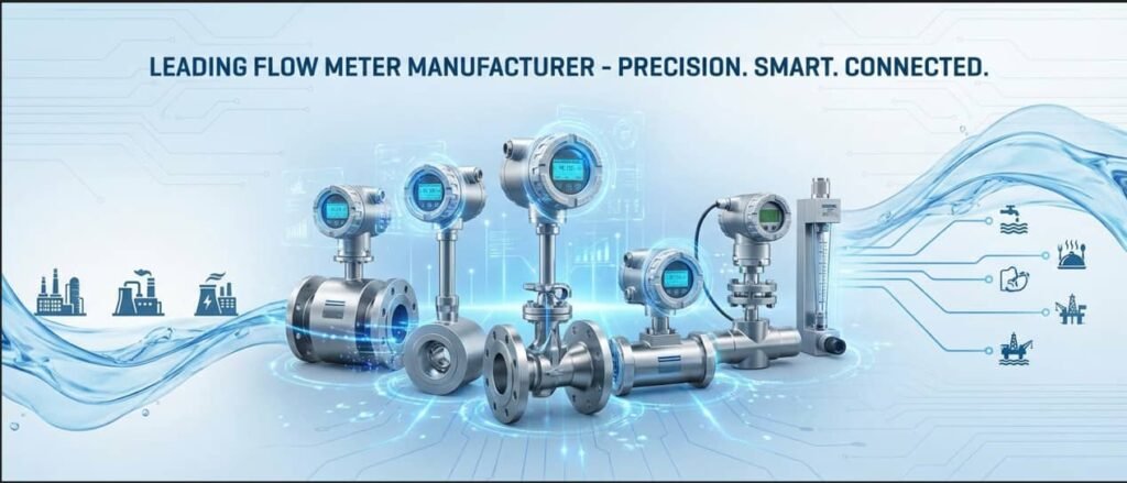
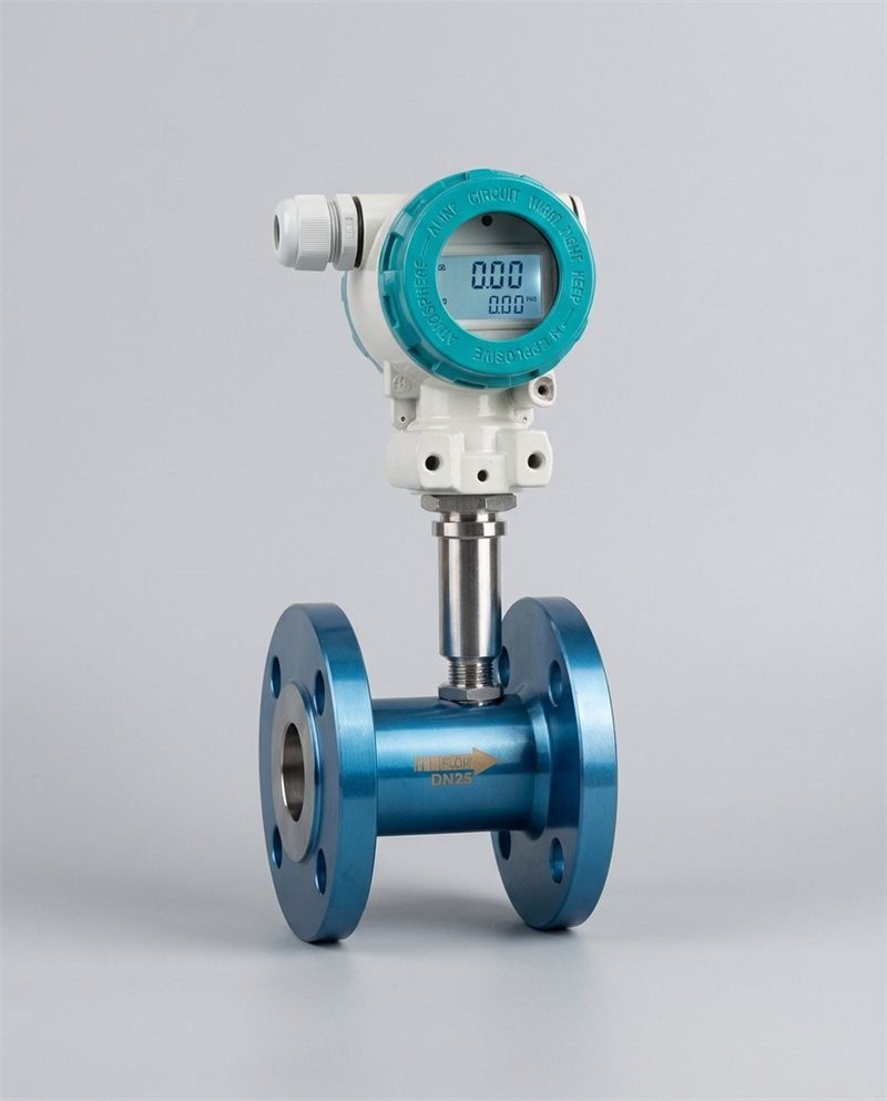
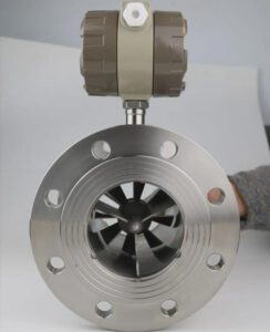
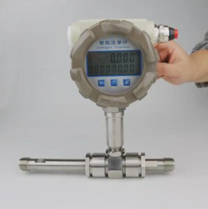
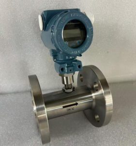
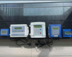
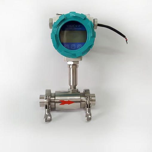
Image: Jade Ant Instruments product photo.
Quick answer: A steam turbine and a turbine flow meter both turn moving fluid into rotation. The power plant wants to take as much energy as possible. The meter wants to take almost none. Once you see that difference, it is easier to size a meter, protect its bearings, and keep its readings honest for ten years or more.
I. The Synergy of Rotational Energy
The invisible link between power generation and precision measurement
A 500 MW steam turbine and a 20 mm flow meter on a dosing skid look nothing alike. One fills a building. The other fits in your hand.
Yet both do the same first job. A fluid hits angled blades, and the blades start to spin.
If you buy, build, or maintain either one, that shared habit explains a lot. It explains why a meter reads low after two years. It also explains why a pump needs more power than the drawing said.
The core principle: kinetic energy becomes rotation
Kinetic energy is the energy a fluid has because it moves. Faster fluid carries more of it.
Blades catch part of that energy and turn it into shaft rotation. What happens to the rotation next is the whole difference.
- In a steam turbine, the shaft drives a generator. Rotation becomes electric power.
- In a turbine flow meter, a sensor counts each blade as it passes. Rotation becomes pulses, which become flow data.
Why this matters to your project
Knowing this kinship helps you ask better questions. How much energy does the rotor take from the line? What wears first? What makes the speed drift away from the flow?
Instrumentos Jade Ant builds turbine, magnetic, vortex, and ultrasonic meters. We see the same failure patterns repeat across all of them, and most trace back to rotation, friction, and flow profile.
Who this guide is for
This guide is written for people who live with these meters every day:
- OEM and skid-mount builders who need a compact, repeatable meter in every build.
- EPCs and system integrators who must fit meters into piping that is already drawn.
- MRO and terminal teams who get the call when a reading looks wrong.
- Distributors and importers who must explain why one turbine meter costs more than another.
- Municipal and utility teams who bill customers by the cubic metre.
II. The Physics of Rotation: From Kinetic Energy to Data
Both machines rely on one idea: a moving fluid hands some of its momentum to a rotating part.

Image: Alfaomega, CC BY-SA 3.0 DE, via Wikimedia Commons.
Fluid dynamics and the “impulse” principle
In a steam turbine, steam first passes through nozzles. A nozzle is a shaped opening that makes the steam speed up while its pressure drops. This pressure difference is the push that creates the fast jet.
There are two common designs, and both are described in this overview of steam turbines:
- Impulse blades turn the jet’s momentum into rotation. The pressure drop happens mostly in the nozzle.
- Reaction blades also let pressure fall across the moving blades, so the blades are pushed by the expanding steam.
A flow meter rotor is different. It is not driven by a big pressure step. It is a lightly loaded wheel that the fluid spins on its way past. Its goal is to follow the flow, not to harvest it.
Flow velocity and angular velocity
Faster fluid spins the rotor faster. In a healthy meter, the relationship is close to a straight line.
A rotor with blades turning at a speed in RPM sends a pulse for each blade that passes the sensor:
Worked example:
- A rotor has 6 blades and turns at 2,500 RPM.
- The pickup sees pulses each second, which is 250 Hz.
From rotation to a useful output
| Steam turbine | Turbine flow meter | |
|---|---|---|
| What spins | Heavy multi-stage rotor | Light, low-drag rotor |
| What the shaft does | Drives a generator | Passes blades by a pickup coil |
| Output | Electric power, in MW | Pulses, in Hz |
| Key formula | ||
| Goal | Take the most energy | Take the least energy |
In the power formula, is torque (twisting force) and is angular speed in radians per second. In the meter formula, is the Fator K, which we explain in Section IV.
Worked example for the meter:
- A meter has a K-factor of 1,000 pulses per litre.
- It outputs 250 Hz.
- Flow is litres per second, or 15 litres per minute.
III. Steam Turbines: The Macro-Application of Power
In power generation, the goal is simple: pull out as much energy as the steam can give.
High-pressure steam expansion and blade geometry
Modern plants often run steam above 500 °C and above 150 bar. As steam moves through the turbine, it expands. Its pressure and temperature fall, so the steam volume grows many times over.
That is why blades get longer from the inlet to the exhaust. Each stage must be shaped for the steam it sees. A small error in blade shape means lost energy in every stage after it.
Thermal stress and centrifugal force in heavy-duty equipment
Hot, fast, heavy parts create two big stresses:
- Thermal stress. Metal expands when it heats. When a rotor warms faster at the surface than at the core, it develops internal stress. That is why large turbines are warmed up slowly.
- Centrifugal stress. Spinning parts try to throw themselves outward. For a simple spinning ring, the stress is:
Here is material density, is angular speed, and is radius. Because speed is squared, a 10% overspeed raises the stress by about 21%. That is why overspeed trips are a core safety system.
Industry insight: Wet steam is quietly expensive. Water droplets in the last stages hit blades at high speed and erode the leading edges. A commonly cited design guide is to keep exhaust moisture at roughly 10–12% or less. Many OEMs add moisture separators for this reason.
Efficiency losses at utility scale
Small percentages add up fast. Here is an illustration with assumed numbers.
| Assumption | Value |
|---|---|
| Plant output | 100 MW |
| Operating hours per year | 8,000 |
| Value of power | 50 USD per MWh |
| Yearly revenue | 40,000,000 USD |
| Value of 1% lost efficiency | 400,000 USD per year |
A good flow measurement system helps because you cannot tune what you cannot measure. Feedwater, steam, and condensate readings feed the efficiency calculation. If those readings are off by 1–2%, the efficiency number you act on is off too.
IV. Turbine Flow Meters: The Micro-Application of Precision
In measurement, the goal flips. You want the rotor to take as little energy as possible, so it follows the flow without changing it.

Image: Ruben Castelnuovo, CC BY-SA 3.0, via Wikimedia Commons.
Low-friction bearings and the quest for low pressure drop
Pressure drop is the pressure the fluid loses as it passes through a device. Your pump has to make that pressure up, every hour it runs.
For a turbine meter, pressure drop rises roughly with the square of flow:
The chart below uses a meter rated at 0.5 bar at full flow. Jade Ant’s published comparison for a 4-inch (DN100) turbine meter on water shows a range of about 0.3–0.7 bar at rated flow, so 0.5 bar is a fair middle value.
Running at 60% of the meter’s maximum flow costs about 0.18 bar, not 0.3 bar. Sizing the meter so normal flow sits at 50–70% of its maximum is one of the cheapest energy savings you can make.
The K-factor and calibrating rotation to volume
O Fator K is the number of pulses the meter produces per unit of volume, such as pulses per litre. Every meter has its own, because rotor shape, bearing drag, and pickup position vary slightly.
Turbines Incorporated’s explanation of the K-factor gives a clear example. With 10,000 pulses per gallon and 5,000 Hz, flow is 0.5 gallons per second.
The K-factor is found by calibration. The meter is run against a reference, and the pulses are divided by the known volume.
Image: NIST. Source page: NIST turbine meter calibration.
NIST calibrates turbine meters with a 20 L piston prover that has a stated uncertainty of 0.074% (95% confidence). It also shows that K plotted against Reynolds number collapses into one curve above about Re = 2,000. This is the “viscosity-independent range.” Below it, bearing drag from viscosity bends the curve.
Plain-English term: Reynolds number. A number that tells you whether flow is smooth or turbulent. Higher numbers mean more turbulent, which turbine meters like.
Solving the “slippage” problem in low-viscosity fluids
Slip is the gap between how fast the rotor should turn and how fast it does turn. At low flow, bearing drag and blade-tip losses hold the rotor back. The meter then reads low.
Here is what helps:
- Stay in range. Most turbine meters work best across a 10:1 turndown. Keep normal flow above the bottom 10–20% of the range.
- Pick the right size. An oversized meter spends more time near its weak low-flow end.
- Check the lowest flow, not just the average. Night flow on a utility line is often lower than anyone remembers.
- Calibrate on a fluid close to your own. O ViscoCorrect education page from Webtec explains how the K-factor curve changes with viscosity.
For a visual walkthrough of how the rotor, pickup, and calibration fit together, watch the video below.
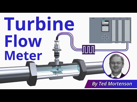
Video: “Turbine Flow Meter Explained | Operation and Calibration” by RealPars. Click the image to watch on YouTube.
V. Critical Comparison: Power Generation vs. Fluid Measurement
The mechanics match. The engineering priorities do not.
Robustness (turbines) vs. sensitivity (flow meters)
A steam turbine is built to survive. It has thick shafts, big bearings, and a lot of safety margin. A flow meter rotor is built to respond. It is light, so even a small flow change moves it.
That sensitivity is the price of accuracy. A speck of debris that a power turbine ignores can slow or jam a meter rotor.
Energy output (work) vs. data output (information)
| Question | Steam turbine | Turbine flow meter |
|---|---|---|
| What is the product? | Power | Information |
| What is a good day? | Maximum output | Rotor follows flow with the least drag |
| What is a bad day? | Efficiency falls | Reading drifts from true flow |
| Who notices first? | The grid operator | The auditor or the quality manager |
Maintenance cycles: overhauling rotors vs. calibrating sensors
Image: NIST, from the NIST turbine meter page cited above. NIST shows both dual-rotor and single-rotor meters.
| Steam turbine | Turbine flow meter | |
|---|---|---|
| Typical planned work | Scheduled outage and rotor inspection | Verification and recalibration |
| Typical interval | Measured in years | 6–36 months, depending on duty |
| Main cost | Outage and labour | Meter removal, lab fee, and downtime |
| Main risk if skipped | Vibration, blade damage, forced outage | Drift that hides in the data |
Turbines Incorporated’s published guidance is a handy benchmark: 6–12 months for custody transfer and billing, 1–2 years for process control, and 2–3 years for non-critical monitoring. Jade Ant’s turbine meter guide for distributors says every 24 months can work if fluid conditions are stable and the first two calibrations show stability.
VI. Solving Client Pain Points: Reliability and Wear
Anything that rotates will wear. The trick is knowing where, how fast, and what the early warning looks like.
Bearing failure and lubrication strategies in skid-mount systems
Most turbine meters are process-lubricated. The fluid itself lubricates the bearings. That works well in clean oil or water. It works poorly with low-lubricity fluids such as light naphtha or acetone.
Jade Ant’s published chemical-plant guide notes that bearings in standard designs often need inspection or replacement every 12–24 months on continuous duty, and sometimes every 6 months on low-lubricity fluids. It also notes that particles above roughly 100 microns can damage bearings and blade edges.
Here is a general comparison. Always confirm details with the specific manufacturer.
| Bearing style | Where it usually works well | Watch out for |
|---|---|---|
| Ball bearing | Clean, low-viscosity liquids and gas; very low drag | Dirt and poor lubrication shorten life |
| Sleeve bearing (for example tungsten carbide) | Dirty or low-lubricity fluids; higher pressure | Slightly higher drag at very low flow |
| Ceramic or hard-coated surfaces | Abrasive or aggressive media | Cost; brittle if hit by hard debris |
For a skid, add three habits: an upstream strainer, a clear cleaning schedule, and a bearing spare in the box.
How fast can wear show up? In one dosing-skid case documented by Jade Ant, turbine bearings lost about 0.3% accuracy per month under normal duty. In a different case on clean methanol, K-factor stayed within 0.15% over 18 months. Same technology, different fluid and upkeep.
Industry insight: A meter that wears evenly drifts low. That is the dangerous direction for a seller or a utility, because lost revenue does not trigger any alarm.
Mitigating cavitation and erosion in high-velocity streams
Cavitation is when liquid pressure drops low enough for vapour bubbles to form. The bubbles collapse as pressure recovers, and they pit metal and upset the rotor. The cavitation overview on Wikipedia shows what that damage looks like.
A common rule of thumb for the minimum back pressure downstream of a liquid turbine meter is:
Here is the meter’s pressure drop and is the fluid’s vapour pressure. Confirm the exact formula with your supplier.
Illustrative example:
- The meter drops 0.3 bar.
- The fluid’s vapour pressure at operating temperature is 0.5 bar.
- Minimum back pressure is about bar.
Erosion comes from speed and solids. Keep velocity inside the rated range and filter the line.
Predictive maintenance: from vibration to pulse trends
Large turbines use vibration probes to catch faults early. Flow meters rarely have them. The equivalent warning signs live in the pulse signal and the trend.
| What you see | Likely cause | What to do |
|---|---|---|
| Reading slowly falls over months | Bearing wear or a partly blocked strainer | Clean the strainer, then verify the meter |
| Erratic readings | Air pockets or flow disturbance | Check the filter and upstream pipe |
| Zero reading while fluid flows | Sensor failure or wiring fault | Test the pickup and cable |
| Weak or uneven pulses | Pickup ageing or rotor fouling | Inspect the rotor and pickup gap |
| Pulses at zero flow | Electrical noise or debris | Check shielding and grounding |
Jade Ant’s gas and steam turbine page lists a similar set of faults, plus a routine of daily checks, monthly strainer cleaning, and an annual rotor inspection.
VII. Integration Challenges for System Integrators and EPCs
Fitting a rotating meter into a larger loop is mostly about matching, shielding, and straight pipe.
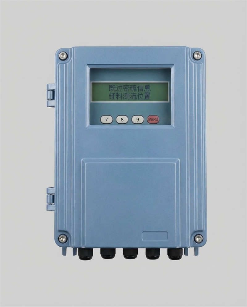
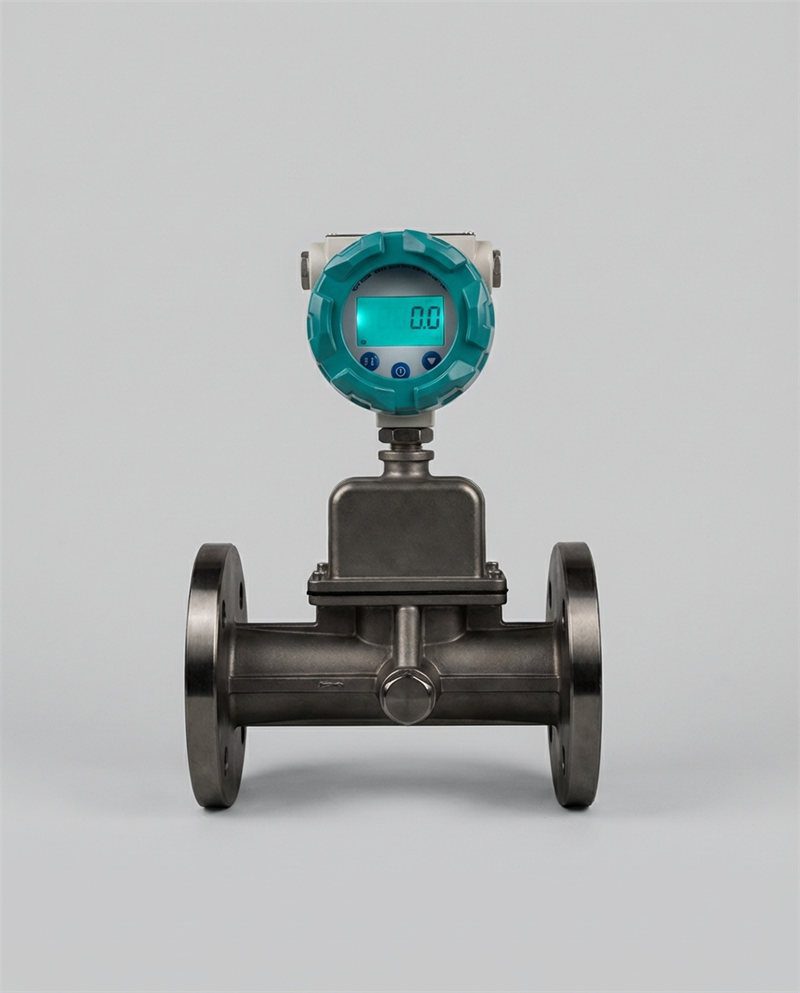
Image: Jade Ant Instruments product photo.
Matching meter specifications to the fluid properties of the power cycle
Steam and condensate lines are demanding. Jade Ant’s gas and steam turbine flowmeter lists these specifications:
| Parâmetro | Specification |
|---|---|
| Size | DN15–DN300 |
| Precisão | 0.5% standard, 0.2% optional |
| Fluids | Gas, steam, compressed air |
| Temperature | −20 °C to +300 °C |
| Pressure | Up to 10 MPa (higher on request) |
| Velocity range | 0.5 m/s to 20 m/s |
| Resultados | 4–20 mA, pulse, RS-485 Modbus RTU |
| Power | 24 VDC or 220 VAC |
| Protection | IP65 standard, IP68 optional |
| Certificações | CE, ISO 9001, ATEX explosion-proof |
For superheated steam above that temperature, a different meter may fit better. Jade Ant’s vortex flow meter for steam and gas covers one option, and its vortex product page lists a high-temperature version rated to 350 °C. Match the meter to the worst case in your cycle, not the daily average.
For hazardous areas, check that ATEX or IECEx certification covers the exact model. The IECEx system lists approved certification bodies.
Signal interference and good pulse transmitters
A pulse signal is weak and fast. Noise from motors and drives can add false pulses, or hide real ones.
Use this checklist:
- Use shielded twisted-pair cable, and ground the shield at one end only.
- Keep signal cable at least 300 mm from power cables. Cross them at 90 degrees.
- Check that the PLC input can count the meter’s top frequency. Jade Ant’s OEM accuracy guide gives an example of a 1,200 Hz meter wired to a 1,000 Hz input, which undercounts at high flow.
- Use a pulse transmitter or converter with a stable output stage if the cable run is long.
- Where you need diagnostics, add digital output. Turbines Incorporated’s protocol explainer and the open Modbus specification help your controls team choose.
Piping layouts that remove turbulence before the rotor
Elbows and valves make fluid swirl. A swirling stream pushes unevenly on the blades and changes the rotor speed without changing the flow.
| Upstream disturbance | Typical upstream straight run | Downstream |
|---|---|---|
| One 90° elbow | About 10 pipe diameters | About 5 diameters |
| Two elbows, same plane | About 15 diameters | About 5 diameters |
| Two elbows, different planes | 20 diameters or more | About 5 diameters |
| Partly open valve | 20 diameters or more | About 5 diameters |
Values follow general guidance in Jade Ant’s turbine vs ultrasonic comparison for chemical plants. Always confirm with your meter’s manual.
On a DN100 line, 15 diameters equals 1.5 m. If you do not have that, add a flow conditioner about 5 diameters upstream, which can cut the effective requirement to roughly 5–10 diameters. Jade Ant’s turbine meter installation and calibration guide also warns that a gasket sticking into the bore can move a meter away from its calibrated K-factor.
VIII. Economic Impact: Reducing Total Cost of Ownership (TCO)
The cost of “measurement drift” in billing and process control
Measurement drift is a slow shift in a meter’s readings away from true flow. It rarely triggers an alarm.
Here is what it costs on a 100 m³/h line running all year, valued at 1.50 USD per cubic metre (an assumption you should replace with your own price):
A third-party example from Turbines Incorporated shows how this plays out. A fuel terminal saw a 1.5% gap between delivered and billed volume. Recalibration found that bearing wear had shifted the K-factor by about 1.6%.
Good traceability helps you catch this early. NIST’s guidance on metrological traceability explains why a calibration certificate needs an unbroken chain to a national standard, and ISO/IEC 17025 sets the competence rules for calibration labs.
Energy recovery through efficient turbine design
Steam systems often drop pressure across a control valve, which wastes energy as heat. A back-pressure steam turbine can sit in that spot and make power instead. This is common in process plants with a steady steam demand.
The ideal calculation is simple:
Illustrative example (assumptions, not a project quote):
- Steam flow kg/s
- Enthalpy drop kJ/kg
- Turbine efficiency
- Power kW
- At 8,000 hours and 0.08 USD per kWh, that is about 336,000 USD per year.
You need a trustworthy steam flow reading to size this, and to prove it afterward.
Reducing downtime with standardized parts for OEM manufacturers
Here is a 10-year cost model for one DN100 turbine meter. The assumptions are listed, so you can replace them with your own quotes.
| Assumption | Value |
|---|---|
| Line flow | 100 m³/h, all year |
| Meter maximum flow | 160 m³/h |
| Pressure drop at maximum | 0.5 bar |
| Pump and motor efficiency | 70% |
| Power price | 0.10 USD per kWh |
At 100 m³/h, the drop is bar. Pump power is W. Over 8,760 hours, that is about 679 USD per year, or 6,790 USD over ten years.
| Cost (10 years) | USD |
|---|---|
| Purchase | 2,500 |
| Instalação | 1,200 |
| Calibration (10 × 300) | 3,000 |
| Bearing and rotor service | 2,400 |
| Pumping energy | 6,790 |
| Total | 15,890 |
Pumping energy is 43% of the total, and the purchase price is only 16%. Standard parts help here. If an OEM uses one meter family across skids, the same bearing kit, strainer, and pickup work everywhere. Jade Ant’s OEM accuracy guide makes the same case for a pre-shipment verification step, which stops a drifted meter from leaving the factory.
IX. Future Trends: Digitalization of Rotational Mechanics
The shift now is from “a rotor that spins” to “a rotor that reports.”
These are directions the industry is moving in, not claims about any one product.
IoT integration for real-time flow and power monitoring
A pulse count is only the start. Add a Modbus link, and the same meter can feed totals, alarms, and trend data into SCADA or the cloud. Jade Ant’s gas and steam turbine meter already offers RS-485 Modbus RTU, and its maintenance guide suggests archiving flow data each quarter for trend analysis.
Watch for slow trends, not just alarms. A small, steady fall in readings versus a downstream check meter is an early bearing warning.
Advanced materials to reduce friction and wear
Ceramics and hard coatings cut wear in bearings and shafts. Composites can make lighter rotors that respond faster at low flow. Before you pay for them, ask for field-life data on your fluid.
AI-driven diagnostics for autonomous calibration
Software is starting to learn what a healthy pulse pattern looks like, then flag departures. The caution is traceability. A regulator wants a calibration chain, not a model’s guess. Use AI to decide quando to verify. Keep the verification itself traceable.
For a comparison of how other technologies handle diagnostics, Jade Ant’s smart ultrasonic flow meter article shows what wireless and touchscreen setup looks like on a different meter type.
X. Engineering Excellence Through Mechanical Harmony
Recap: steam power and fluid measurement
Both machines turn moving fluid into rotation. The power turbine takes as much as it can. The flow meter takes as little as it can. In both, speed, friction, flow profile, and wear decide how well the machine does its job.
What this means for your role
- OEMs: Pick the bearing and strainer package for the fluid, not for the brochure. Verify before shipping.
- EPCs and integrators: Put straight run, shielding, and back pressure on the drawing. Check top pulse frequency against the PLC.
- MRO and terminals: Trend readings against a check meter. Clean strainers on a schedule.
- Distributors: Sell the 10-year number. Pumping energy and calibration often outweigh the purchase price.
- Municipal and utility teams: Keep normal flow inside the meter’s good range, and calibrate on a traceable schedule.
If you are sizing or replacing turbine meters, send Jade Ant Instruments your fluid, line size, flow range, and temperature through the contact page. Their team can check straight run, back pressure, and protocols before you order.
For a side-by-side look at where turbine meters sit against other technologies, see Jade Ant’s Coriolis, magnetic, turbine, and ultrasonic comparison. For a general sizing checklist, the flow meter selection guide covers the basics.
Glossário de termos-chave
Cavitation: Vapour bubbles that form when liquid pressure falls too low, then collapse and damage metal. Example: a rotor that looks pitted after a pump runs with low suction pressure.
Impulse and reaction blades: Impulse blades turn a fast jet’s momentum into rotation. Reaction blades are also pushed by pressure falling across the moving blades.
K-factor: Pulses produced per unit of volume. Example: 1,000 pulses per litre.
Measurement drift: A slow shift in readings away from true flow. Example: a meter that reads 1.6% low after 18 months of bearing wear.
Nozzle: A shaped opening that speeds up fluid and drops its pressure.
Pressure drop: Pressure lost as fluid passes through a device. Example: 0.195 bar across a meter at 62% of maximum flow.
Process-lubricated bearing: A bearing lubricated by the fluid being measured.
Pulse output: A signal that sends one electrical pulse for each blade that passes the pickup.
Reynolds number: A number that describes how smooth or turbulent a flow is.
Slip: The gap between ideal rotor speed and real rotor speed, worst at low flow.
Straight run: Straight pipe before and after a meter that lets swirl settle.
Turndown: The ratio of highest to lowest accurate flow. Example: 10:1.
Perguntas frequentes
1. For OEMs: How does the choice of bearing material in a flow meter affect the overall lifespan of a skid-mount system?
Bearings are the first wearing part, so they set the service interval for the meter. Ball bearings give very low drag on clean fluids but tolerate dirt poorly. Sleeve bearings, such as tungsten carbide, usually handle grit and low-lubricity fluids better. Jade Ant’s chemical-plant guidance notes that standard bearings often need attention every 12–24 months, and as often as every 6 months on fluids like acetone. Match the bearing to the fluid, add an upstream strainer, and ship a spare bearing kit with the skid.
2. For EPCs: What is the maximum allowable pressure drop across a turbine meter before it hurts the steam cycle, and what is the trade-off between accuracy and rotor resistance?
There is no single limit. It depends on how much pressure your line can spare. A 0.5 bar drop on a 40 bar steam line is only 1.25% of line pressure, but the same drop on a low-pressure condensate line could matter a lot. Pressure drop rises with the square of flow, so a meter running at 60% of its maximum loses roughly 36% of its rated drop. Heavier, more rugged rotors can handle more abuse, while lighter rotors respond better at low flow. Choose the size where normal flow sits at about 50–70% of maximum, and ask your supplier for the pressure-loss curve at your actual flow.
3. For utility companies: How often should turbine-based measurement systems be recalibrated to maintain municipal billing accuracy?
Start with your local weights-and-measures or water authority rules, which take priority. As a benchmark, Turbines Incorporated suggests every 6–12 months for billing and custody transfer, 1–2 years for process control, and 2–3 years for non-critical use. Jade Ant’s distributor guide notes that 24 months can work when fluid conditions are stable. Use your first two calibrations to measure real drift, then set the interval so that drift would hit your accuracy limit only after the next check. Keep every certificate with its traceability statement.
4. For MRO companies: What are the primary indicators of premature rotor wear, and can turbine meters be serviced in-situ?
Watch for these signs:
- A slow fall in readings against a downstream check meter.
- Weak or uneven pulses.
- Pulses at zero flow.
- A rising gap between as-found and as-left calibration.
- Rough or noisy rotation if you can inspect it.
Many turbine meters can be opened and serviced on site, because the parts are mechanically simple. Jade Ant’s published guidance notes that an experienced technician can often diagnose and repair a meter in under two hours. You still need isolation, depressurizing, and a verification run afterward. A meter that has had its bearings or rotor changed should be verified before it returns to service.
5. For distributors: Which fluid viscosities are incompatible with turbine-based measurement, and what are the alternatives?
Standard designs work best with thin fluids, roughly below 10–15 cSt. Above that, bearing drag grows, the K-factor curve bends, and usable range can shrink by 30–50%. Very thick fluids call for a different technology. Magnetic meters suit conductive liquids regardless of viscosity. Positive displacement or Coriolis meters suit thick, non-conductive fluids. Ultrasonic meters can work if the fluid is not too attenuating. Ask for the coldest startup viscosity, because a fluid that is thin at 60 °C can be thick at 15 °C.
6. For system integrators: How do you eliminate turbulence in a piping run so the turbine meter sees steady flow?
Give the flow room to settle. Plan 10–15 pipe diameters upstream and about 5 downstream, and more after double elbows or partly open valves. If space is short, install a flow conditioner about 5 diameters upstream. Keep gaskets from sticking into the bore. Do not place a control valve right before the meter. Put the straight-run length on the P&ID, before the pipe is cut.
7. For OEMs: Can the same rotational principles be applied to high-temperature steam measurement as in power generation?
The principle is the same, but a meter must stay light and accurate while a power turbine only needs to survive and produce. Jade Ant’s gas and steam turbine flowmeter is specified to +300 °C and up to 10 MPa. For hotter superheated steam, a vortex meter may be a better fit, and Jade Ant lists a high-temperature option to 350 °C. Check bearing materials, pickup limits, and ATEX needs at your worst-case temperature.
8. For utility companies: How does “slippage” in a turbine meter lead to revenue loss in large-scale fluid transport?
Slip makes the rotor turn slower than the flow would suggest, mostly at low flow. The meter then under-reads, so you deliver water or fuel that you never bill. At 1.50 USD per cubic metre, a 1% bias on a 100 m³/h line is about 13,140 USD a year. On a 1,000 m³/h main, the same bias is about 131,400 USD. To limit slip, keep the meter in its good range, avoid oversizing, and check low-flow behaviour at night when demand is lowest.
9. For EPCs: What is the impact of fluid density changes on the K-factor of a rotational flow meter?
For liquids, the K-factor is mostly set by geometry and viscosity, so a small density change does not move it much. But the meter measures volume, so if you need mass, you must multiply by density. For gases, density matters more. A lighter gas carries less momentum, so the rotor needs more flow to overcome drag, and the low end of the range gets worse. Use pressure and temperature compensation for gas, and calibrate on a fluid close to the real one.
10. For all: How do “smart” transmitters improve the reliability of traditional turbine rotational data?
They add a second look at the same signal. A smart transmitter can apply a multi-point correction, compensate for temperature, flag weak or irregular pulses, log events, and send diagnostics over Modbus or HART. That turns “the reading looks fine” into “the signal looks fine.” For example, Jade Ant’s gas and steam turbine meter offers 4–20 mA, pulse, and RS-485 Modbus RTU. Smart electronics do not fix a worn bearing, but they help you catch one sooner.