Turbine Flow Meter Selection Guide: From Fluid to Integration
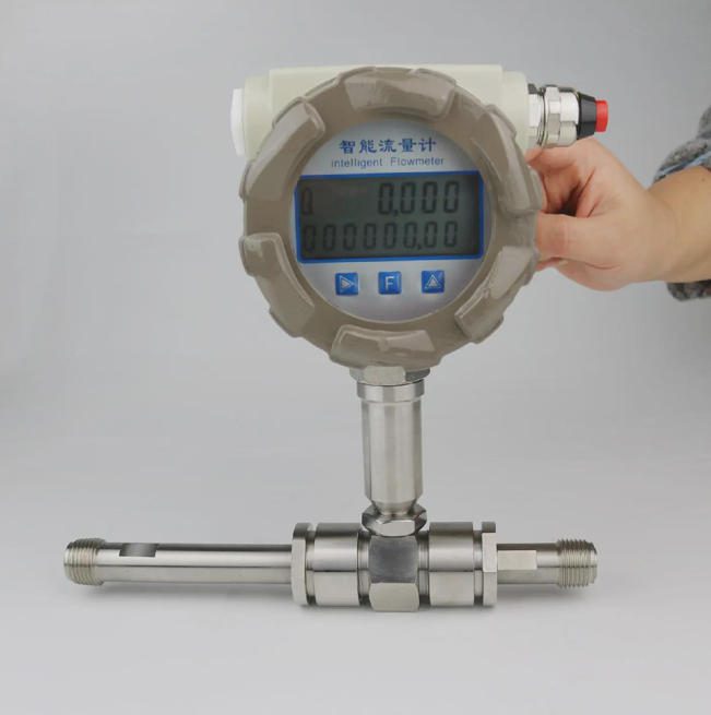
Image: Jade Ant Instruments product photo.
Quick answer: Choose a turbine flow meter in four steps. Start with the fluid, then the pressure and temperature, then the piping, then the signal your PLC reads. Skip a step and you will pay for it later in drift, bearing wear, or a meter that reads zero at night. This guide walks through each step with numbers you can check against your own datasheet.
I. Introduction
A. The critical role of precision flow measurement in industrial efficiency and safety
A flow meter turns a moving liquid into a number. That number decides how much chemical you dose, how much fuel you bill, and how much treated water you send to a town.
If the number is off by 0.5%, it rarely triggers an alarm. It just shows up months later as a yield gap or a billing dispute.
The Jade Ant Instruments guide to turbine meters puts the cost in plain terms. A 0.5% K-factor shift on a pipeline moving 10 million USD of product a year equals 50,000 USD of unaccounted product. The Fator K is the number of pulses the meter sends for each unit of fluid. We explain it fully in Section II.
B. Common pain points in meter selection
Buyers on all sides tell us the same three stories:
- Premature wear. The rotor spins on bearings, and a fluid that is dirty, thick, or not lubricating shortens their life.
- Signal drift. The meter was right at the factory test, but a year later the K-factor has moved.
- Installation errors. A valve sits two pipe diameters upstream, so the rotor sees swirl instead of a steady flow.
None of these are defects. They are selection and installation mismatches, and they are preventable.
C. Objective: a professional framework for OEMs, EPCs, and utility managers
This guide gives you a repeatable path from fluid to integration. It is written for OEM and skid-mount builders, EPC and system integrators, distributors and importers, industrial MRO teams, and municipal utilities.
It builds on the five-factor selection framework from Jade Ant Instruments and adds turbine-specific checks.
Thesis in one line: Match the meter’s design to the fluid and the pipe layout, and a turbine meter delivers long-term accuracy at a low cost. Ignore the match, and you buy a replacement.
II. Defining Fluid Characteristics and Chemical Compatibility
A. The fluid dictates the materials
A turbine meter puts a spinning rotor directly in the flow. So the fluid touches the body, rotor, shaft, and bearings. Before you compare prices, write down four things about the fluid: viscosity, density, chemistry, and cleanliness.
B. Viscosity and density: how fluid thickness affects rotor drag and linearity
Viscosity is how thick a liquid is. It is measured in centistokes (cSt). Water at room temperature is about 1 cSt, and motor oil is 100–300 cSt.
Thicker fluid drags on the rotor. At low flow the rotor then spins slower than it should, and the K-factor changes with it. This is why linearity (how straight the flow-to-pulse relationship stays) gets worse as viscosity rises.
Here is what the published sources say:
- Hoffer’s engineering guide for liquids reports linearity of ±0.5% of reading or better over a 10:1 range at 0.8–2 cSt. It lists 300 cSt as the usual maximum. That figure comes with conditions: ball bearings, calibration at a similar viscosity, and signal linearization.
- Jade Ant’s own selection table prefers below 50 cSt and treats about 100 cSt as the ceiling for general service.
The two limits are not in conflict. Jade Ant’s number is a safe default for standard meters. Hoffer’s number applies to a specially configured meter. If your fluid is above 50 cSt, ask the supplier for a meter calibrated at your operating viscosity.
O Dwyer Omega turbine meter overview adds a useful rule: turbine meters work well when the Reynolds number sits between 4,000 and 20,000. The Reynolds number compares the fluid’s momentum to its stickiness. Above 4,000, the flow is turbulent and behaves predictably.
Density matters less. Dwyer notes that density changes do not greatly affect accuracy. On light fluids (specific gravity below 0.7), the minimum flow goes up because the rotor gets less push.
Industry insight: Viscosity problems often show up at cold start, not at normal running temperature. A fluid that is 3 cSt at 60 °C can be 40 cSt at 10 °C. Check the viscosity at the coldest moment your skid will run, not just the datasheet value.
C. Chemical compatibility: matching wetted parts to aggressive media
Wetted parts are the parts that touch the fluid. Match them to the chemistry, including cleaning agents and process upsets.
| Part | Common options | Typical reason to choose it |
|---|---|---|
| Body | 316/316L stainless steel | Water, fuels, light chemicals |
| Rotor | 17-4 PH, Nickel 200, 430 stainless, PTFE | Match to the fluid; PTFE for chemical-only service |
| Bearings | Hybrid ceramic ball, hard carbon, tungsten carbide, PTFE/PEEK | See the bearing table in Section VIII |
| Special alloys | Hastelloy C-276, titanium | Dilute acids, chlorinated solvents, seawater |
Sources: Hoffer’s engineering guide and the Jade Ant turbine guide.
Two cautions apply:
- Hoffer’s PTFE-lined series is only recommended for viscosities of 3 cSt and below.
- Always check the material against the maximum temperature, not room temperature.
When a line carries corrosive or high-purity fluid and the meter cannot tolerate wetted parts, compare technologies first. The turbine versus ultrasonic comparison for chemical plants shows where a non-contact meter becomes the safer pick.
D. Fluid cleanliness: do you need a strainer?
Yes, in almost every liquid service. A strainer is a mesh filter in the pipe that catches debris before it reaches the rotor.
Dwyer’s guidance is specific: if suspended solids exceed 100 mg/L of particles larger than 75 microns, install a flushing Y-strainer or cartridge filter at least 20 pipe diameters upstream. Jade Ant’s guide recommends a 25–75 micron strainer in liquid service.
Hoffer’s table gives mesh by meter size:
| Meter size | Mesh | Max particle (inch) | Max particle (µm, approx.) |
|---|---|---|---|
| 1/4″ to 1/2″ | 100 | 0.0055 | 140 |
| 5/8″ to 1-1/4″ | 80 | 0.007 | 178 |
| 1-1/2″ to 3″ | 40 | 0.015 | 381 |
| 4″ to 12″ | 20 | 0.031 | 787 |
Source: Hoffer’s engineering guide for liquids, Table 2. Micron values are converted from the inch figures.
The pattern is simple: the smaller the meter, the finer the mesh.
III. Analyzing Process Conditions: Pressure and Temperature
A. Environmental extremes can compromise seals and calibration
Pressure and heat attack the soft parts first. They also change the fluid itself. Treat both as design inputs, not afterthoughts.
For gas or steam service, use a gas-specific design. A liquid meter’s rotor will over-speed in gas. See the gas and steam turbine flow meters page for the product range.
B. Pressure ratings: matching flange ratings to peak system pressure
Check the peak pressure, including pump surges and thermal expansion, not just normal pressure. Then match the flange class.
Hoffer’s published ratings show how much the limit changes by size:
| Meter size | Max ANSI class (flanged) | Max working pressure |
|---|---|---|
| 1/4″ to 1/2″ | Up to 2500# | 6,170 psig (419 bar) |
| 1″ to 1-1/4″ | Up to 2500# | 5,000 psig (340 bar) |
| 2-1/2″ to 4″ | Up to 900# | 2,200 psig (149 bar) |
| 10″ | Up to 400# | 990 psig (67 bar) |
| 12″ | Up to 400# | 800 psig (54 bar) |
Source: Hoffer’s engineering guide for liquids, Table 7. The flange material you choose can lower these limits, so confirm with the supplier.
Small bodies handle the highest pressures, which is why compact barstock designs are common in hydraulic and dosing service.
C. Thermal expansion: temperature changes the fluid and the metal
Two things move when the temperature moves:
- The fluid. Its volume and viscosity change. A volume-based meter reads a different mass of fluid at 60 °C than at 15 °C. Add a temperature sensor and a flow computer if your units are mass.
- The metal. Clearances inside the meter change slightly, which can shift the K-factor.
Dwyer lists the operating range of turbine meters as −200 to 450 °C, but the usable range for your meter depends on its bearing and pickup coil. Hoffer’s standard magnetic coil covers −268 to +232 °C and an optional version reaches +454 °C.
D. Seal and bearing selection: vacuum, high pressure, and fluid type
Turbine meters should only run in positive-pressure lines. Hoffer states they will not perform well under vacuum. They also need back pressure so the meter stays full of liquid.
Hoffer’s minimum back pressure for volatile liquids uses this formula:
Here ΔP is the meter’s pressure drop at maximum flow, in psi. P_e is the vapor pressure of the liquid at operating temperature, in psia. P_b comes out in psig.
Worked example: a solvent with a vapor pressure of 5 psia, and a meter drop of 3 psi at full flow:
That is the minimum back pressure downstream of the meter. A simple rule from Hoffer for non-volatile liquids is 5–10 psig.
IV. Evaluating Accuracy Requirements and Repeatability
A. Balance precision against real-world turbulence
Accuracy on a datasheet comes from a clean lab line. Your pipe is not a clean lab line. So separate what the process needs from what the datasheet offers.
B. Custody transfer vs. process control accuracy
Custody transfer is a flow measurement that sets who pays whom, such as fuel loading or water billing. Process control uses the number to run the plant.
| Use | Typical accuracy needed | Typical interval between calibrations |
|---|---|---|
| Custody transfer / billing | 0.1–0.5% | 6-12 meses |
| Pharmaceutical dosing | 0.5–1% | About 12 months |
| Process control | 0.5–1% | 1 a 2 anos |
| Non-critical monitoring | 1–2% | 2 a 3 anos |
Intervals follow the Turbines Incorporated and Jade Ant guides. Your contract or local rules may require shorter ones.
A quick test turns accuracy into litres. On a 500 L batch, 1% accuracy is a 5 L swing. At 0.25% it is 1.25 L. If your customer’s tolerance is ±2%, the cheaper grade is enough.
C. Linearity and rangeability
Rangeability (also called turndown) is the ratio of the highest to the lowest flow the meter measures within its stated accuracy.
Dwyer’s guidance gives the numbers: barstock turbines are typically linear to ±0.25% of reading over a 10:1 range, and larger meters to ±0.5%. Hoffer reports repeatability of ±0.1% of reading over 20:1 up to 100:1 with the right coil and bearing.
There is a catch. Turbine meters show a small non-linearity, the “hump,” in the lowest 25–30% of their range. Keep your minimum flow above that region and linearity improves to about ±0.15% on small meters and ±0.25% on larger ones.
D. Calibration standards
For regulated or billing work, ask for a calibration traceable to national standards. NIST’s guidance on metrological traceability explains why a certificate needs an unbroken chain of comparisons. Hoffer’s standard factory calibration is a 10-point test at 1 cSt, traceable to NIST under ISO 9001 and ISO 17025 systems. Other viscosities are available as options.
Ask where the calibration was done. The Fluke calibration best practices guide stresses calibrating at actual operating conditions. A water calibration is a poor proxy for a viscous oil.
V. Installation Geometry and Piping Requirements
A. Improper piping is the leading cause of turbine meter error
A turbine rotor measures the average speed of the fluid it sees. If the fluid is swirling, or fast on one side, the rotor reads the wrong average.

Image: Ruben Castelnuovo, CC BY-SA 3.0, via Wikimedia Commons.
B. Straight-run requirements: eliminating swirl
Straight run is the length of straight pipe before and after the meter. It is measured in pipe diameters (D). For a DN50 line, 1D is about 50 mm.
Dwyer’s guidance is specific:
- 10–15D upstream and 5D downstream as the baseline.
- 20D upstream after a 90° elbow, tee, filter, strainer, or thermowell.
- 25D after a partially open valve.
- 50D or more after two elbows in different planes, or if the flow is spiraling.
Chart converts Dwyer’s diameters into millimetres for a DN50 pipe. The clean-inlet bar uses the conservative 15D figure.
Note the strainer. It adds a 20D requirement of its own, so place it far enough upstream to give the flow time to settle.
C. Flow profilers: when space is tight
A flow conditioner (or straightening vane) is a tube bundle or vane set that removes swirl. Dwyer places them at least 5D upstream of the meter. Hoffer’s meters use tube bundles inside the body to support the shaft and do some conditioning, and for custody transfer an additional upstream tube bundle is normally required.
For compact skids, this is the tool that saves your layout. Add a conditioner in the drawing from the start, and confirm with the supplier how much straight run it saves for your particular meter.
D. Orientation and mounting: horizontal vs. vertical
Hoffer’s rules for liquid service are clear:
- Horizontal is the default.
- Vertical or slanted is fine if the flow goes up through the meter.
- Downward flow is not recommended. It is hard to keep the line full, and it speeds up bearing wear.
Air pockets cause the rotor to spin irregularly and the readings to jump. Vent the high points, keep the meter full, and provide the back pressure from Section III.
For a fuller checklist on torque, wiring, and commissioning, see the installation best practices guide. It is not limited to turbines and covers the common mistakes by cost.
VI. Integration with Control Systems and Signal Output
A. The meter must talk to your PLC or SCADA
A good meter with the wrong output is a project delay. Pick the signal early, because it decides the cable, the card, and the power supply.
B. Output options: pulse, 4–20 mA, Modbus, and HART
| Output | What it carries | Best for | Watch out for |
|---|---|---|---|
| Pulse (frequency) | One pulse per fixed volume | Batching, totalizing, custody transfer | Counter input must be fast enough |
| 4–20 mA | Flow rate as a current | Analog control loops | Needs a transmitter; one variable |
| HART | Digital data on top of 4–20 mA | Remote setup and diagnostics | Loop resistance limits |
| Modbus RTU/TCP | Many values on one network | SCADA and multi-meter skids | Unique addresses; register map |
For a plain-language overview of these protocols, the protocol primer from Turbines Incorporated is a good starting point, and the Modbus Organization publishes the open specification.
How to size a pulse input. Turn flow into frequency with the K-factor:
Example: K = 100 pulses per litre, maximum flow 30 m³/h (8.33 L/s):
Choose a counter input rated at least 25% above that, so about 1,050 Hz. The Jade Ant guidance gives a related example: a meter that outputs more pulses per second than the PLC card can count will undercount at high flow, and nobody notices until a yield report.
C. Power supply compatibility
The pickup type decides whether you need power:
- A passive magnetic pickup makes its own signal and needs no power. It is useful at remote sites.
- A Hall-effect or RF pickup needs DC power, and it works at lower flow speeds (Dwyer: about 0.2 ft/s, compared with 0.5–1.0 ft/s for magnetic pickups).
- A 4–20 mA transmitter usually runs as a two-wire loop on 10–30 VDC, as stated in the Jade Ant guide. Confirm the voltage on the datasheet for your model.
Signal distance also changes by pickup type. Dwyer notes that passive pickups can produce only tens of millivolts at low flow, so the cable run to the amplifier must be short. Hall-effect designs can send a stronger signal over much longer cables.
D. Signal conditioning: electrical noise in high-EMI environments
EMI (electromagnetic interference) is electrical noise from motors, drives, and radios. A weak turbine pulse is easy to corrupt.
Practical rules:
- Use shielded twisted-pair cable.
- Ground the shield at the receiving end only, to avoid ground loops.
- Run the signal cable in a separate conduit from power cables.
- Keep the meter body from rigid contact with vibrating equipment, because vibration can create false pulses. Jade Ant suggests isolation mounts above 0.5 g.
If you track down a stubborn noise problem, the diagnostic steps in the grounding and noise troubleshooting guide apply to any low-level meter signal, not just magnetic ones.
VII. Application-Specific Considerations for Target Personas
A. Different stakeholders weigh different things
The same meter gets judged by different tests. Here is what each buyer should push on.
Image: Jade Ant Instruments product photo.
B. For OEMs and skid-mount builders: compact footprint and easy integration
OEMs live and die by space and build time. Look for:
- Compact bodies. The Jade Ant guide describes a DN50 turbine body as roughly 3–5 diameters long.
- Barstock designs. Dwyer notes small turbines are machined from hex bar in 3/4″ to 3″ sizes and handle high pressures, up to 5,000 psig.
- Smaller than the line. If the pipe is oversized and the velocity is under 1 ft/s, Dwyer recommends a Hall-effect pickup and a meter smaller than the pipe.
- Direct pulse output. A pulse goes straight to the batch controller, with no converter needed.
See the liquid turbine flow meter range for the range of sizes and options, and check hazardous-area needs early. Jade Ant’s ATEX-certified flow meters page covers the approval frameworks, and the IECEx certification system lets you check a certificate yourself.
C. For EPCs and system integrators: standardization, documentation, rapid deployment
EPC teams want fewer variants and complete paperwork. Ask for these before award:
| Document | Why it matters |
|---|---|
| Calibration certificate with traceability statement | Audit evidence |
| Material certificates for wetted parts | Compatibility proof |
| Datasheet with K-factor and linearity range | Loop configuration |
| ATEX or IECEx certificate, if relevant | Hazardous-area approval |
| Installation and wiring drawing | Commissioning |
Standardize on two or three sizes and one output type across the project. It trims your spares list and your loop-check time. Knowing how to read a flow meter datasheet helps you spot missing items before you sign. For exports into Europe, the European Commission’s page on CE marking requirements explains what the mark means.
D. For utilities and MRO teams: longevity, ease of maintenance, spare parts
Utilities and MRO teams care about what happens in year five. Key points:
- Field-serviceable cartridges. Many designs let you pull the rotor, bearing, and pickup assembly out without removing the body from the pipe, per the Jade Ant guide.
- Spares. A bearing kit is typically 150–400 USD for industrial sizes (Jade Ant guide).
- Standards for water. In the United States, AWWA Standard C701 sets Class I and Class II rules for water turbine meters. Class I meters must read within 98–102% of actual flow at maximum flow, and Class II within 98.5–101.5% (Dwyer).
- Water quality. Use turbine meters on treated, filtered water. Raw water with sand or grit will destroy bearings within months.
VIII. Maintenance, Lifecycle, and Total Cost of Ownership (TCO)
A. The purchase price is the smallest part of the bill
TCO (total cost of ownership) is everything you spend over the meter’s life: purchase, install, calibration, repair, downtime, and the cost of wrong readings.
The table below is built from the cost ranges in Jade Ant’s turbine guide for a DN50 clean-liquid line. I used the middle of each range. The guide’s own 10-year totals do not match the sum of its rows, so I added the rows myself.
| Cost (10 years, USD) | Turbina | Eletromagnético | Coriolis |
|---|---|---|---|
| Purchase | 2,000 | 2,400 | 9,500 |
| Instalação | 1,000 | 1,250 | 1,600 |
| Calibration events | 1,900 | 1,375 | 1,600 |
| Bearing replacement | 1,100 | 0 | 0 |
| Strainer upkeep | 600 | 0 | 0 |
| Process downtime | 3,000 | 750 | 350 |
| Measurement drift (product loss) | 4,500 | 1,500 | 300 |
| Total | 14,100 | 7,275 | 13,350 |
The result is honest, and it is not a sales pitch. On a conductive liquid, a magnetic meter is cheaper to own, because it has no bearings and drifts less. The turbine’s case rests on other ground: non-conductive fluids, fast pulse output for batching, compact size, and a lower entry price. About half of the turbine’s 14,100 USD is downtime and drift, not hardware.
Energy is not in this table. For a rough number, assume a 0.35 bar drop at 20 m³/h, 70% pump efficiency, and 0.10 USD per kWh:
Running 8,760 hours a year, that is about 243 USD per year. This follows Dwyer’s sizing note: choose a meter that gives 3–5 psid (about 0.2–0.34 bar) at maximum flow. Because pressure drop rises with the square of flow, going one size smaller raises it quickly.
B. Wear analysis: how long will bearings and rotors last?
Bearings are the wear item. Hoffer’s bearing guide shows the trade-offs:
| Bearing type | Temperature range | Strong point | Weak point |
|---|---|---|---|
| Hybrid ceramic ball | −240 to +149 °C | Viscous service; widest flow range | Not for dirty or abrasive fluid |
| Hard carbon composite | −40 to +232 °C | Best general corrosion resistance | Not for viscous service |
| Tungsten carbide | −268 to +454 °C | Best for dirty, abrasive service | Poor corrosion resistance |
Source: Hoffer’s engineering guide for liquids, Table 4.
Real-life intervals depend on the fluid. Jade Ant’s chemical-service guidance sets bearing inspection at 12–24 months for a continuously running line, and notes some plants service meters on low-lubricity solvents such as acetone on 6-month cycles. Its general installation schedule lists a 5–10 year meter lifespan with bearing replacement every 2–3 years.
C. Verification intervals: field check vs. factory recalibration
Think in two tiers:
- Field verification. Check the pulse count against a trusted reference, such as a tank fill or a clamp-on ultrasonic cross-check. It takes little time and catches gross drift.
- Factory or lab recalibration. Do this at the interval for your application (Section IV), after a bearing change, and whenever verification shows a shift beyond your tolerance.
Use the first two calibration cycles to measure real drift. Then set the next interval at the point where drift would reach your accuracy limit, not before.
For deeper background on how the K-factor is set and why it shifts, how the K-factor is determined is a clear reference. It describes a fuel terminal whose billing gap of about 1.5% traced to a 1.6% K-factor shift from bearing wear.
D. Downtime mitigation: redundancy and bypass loops
Plan for service while you draw the pipe:
- Isolation valves upstream and downstream.
- A bypass loop. Hoffer shows this as optional, but it lets you pull the meter without stopping flow.
- A second pickup coil. Hoffer’s dual-coil option gives pulse security for custody transfer. If one coil fails, the other keeps counting.
- A spare cartridge or bearing kit on the shelf, so a repair takes hours and not weeks.
IX. Troubleshooting Common Selection Failures
A. Learn from the usual missteps
Most replacement jobs trace back to one of three mistakes. They look opposite, but all three are mismatches.

Image: Alfaomega, CC BY-SA 3.0 DE, via Wikimedia Commons. Cutaway of a turbine meter body with rotor and supports.
B. Over-specification: the “over-engineered” trap
You pay for features the process never uses. Common examples:
- Custody-transfer grade (up to 5,000 USD in Jade Ant’s price guide) on a line where process grade (300–2,500 USD) would hold the tolerance.
- Exotic alloys for plain water.
- A meter calibrated to 0.1% feeding a control loop that only moves in 1% steps.
Ask one question: what is the tolerance of the process, in litres or kilograms? Buy accuracy to that number and no more.
C. Under-specification: ignoring turbulence, cavitation, and solids
The opposite mistake is quieter and more costly:
- No straight run. See Section V. A meter 3D after a valve can read several percent off.
- Cavitation. Dwyer explains that the pressure drop across the meter can cause flashing, which makes the meter read high, or cavitation, which damages the rotor. The cure is the back-pressure rule in Section III: downstream pressure at least 1.25 times the vapor pressure plus twice the pressure drop.
- Entrained air. Small amounts (about 100 mg/L or less) make the meter read slightly high. Larger amounts can destroy the rotor.
- No strainer. Solids above the limit wear the bearings in months.
D. Mismatched range: operating too close to the minimum flow
This is the most common error in oversized pipes. The meter was sized for the pipe, not the flow.
Check the velocity:
On DN50, the cross-section is about 0.001963 m². At a normal flow of 20 m³/h:
That is healthy. Dwyer’s guidance is that velocities under 1 ft/s (about 0.3 m/s) can be insufficient, while over 10 ft/s (about 3 m/s) can cause excessive wear.
Now imagine the real flow is only 2 m³/h:
That is below the 0.3 m/s guideline. The cure is a smaller meter. A DN25 line (area about 0.000491 m²) carrying the same 2 m³/h runs at about 1.13 m/s.
Dwyer also advises sizing so the average flow is 60–75% of the meter’s maximum. That keeps you out of the low-flow hump.
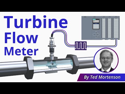
Video: “Turbine Flow Meter Explained | Operation and Calibration” by RealPars. Click the image to watch on YouTube. A step-by-step written walkthrough from RealPars covers the same ground, including how to simulate a turbine signal during loop checks.
X. Conclusion
A. Summary of the systematic approach
Follow one order, and each step narrows the next:
- Fluid. Viscosity at the coldest start, chemistry, cleanliness. This sets materials, bearings, and strainer.
- Process. Peak pressure, temperature, back pressure. This sets the flange class, the coil, and the cavitation margin.
- Installation. Straight run, orientation, conditioner, bypass. This sets the layout.
- Integration. Pulse, 4–20 mA, HART, or Modbus, plus power and shielding. This sets the controls.
If you want to compare technologies at the end, the magnetic, ultrasonic and turbine comparison from Jade Ant Instruments puts them side by side.
B. Final checklist for procurement officers and engineers
Before you issue the purchase order, confirm each of these:
- Viscosity known at the coldest and hottest operating points, and the calibration viscosity stated.
- Wetted materials, bearing type, and rotor checked against the fluid e the cleaning agents.
- Strainer mesh chosen for the meter size.
- Peak pressure, flange class, and back pressure confirmed.
- Straight run drawn on the P&ID, with a conditioner if space is short.
- Normal flow sits at 60–75% of the meter’s maximum, and minimum flow clears the low-range hump.
- Output type matches the PLC card, including maximum pulse frequency.
- Calibration traceability and interval agreed in writing.
- Bypass, isolation valves, and spare kit planned.
- Certificates in hand for hazardous-area and export needs.
C. The value of a technical second opinion
A short review of your data sheet by an application engineer is cheap compared with replacing a meter on a running line. Send the fluid, viscosity range, line size, flow range, pressure, temperature, and available straight run to Jade Ant Instruments’ application engineers. They can check the match before you order. If you buy through a channel partner, the turbine flow meter guide for distributors gives your sales and service teams the same talking points.
For a wider look at the selection process, the step-by-step flow meter selection guide covers all common technologies.
Glossário de termos-chave
K-factor: The number of pulses the meter sends per unit of volume, for example pulses per litre. Example: K = 100 pulses/L at 5.56 L/s gives 556 Hz.
Linearity: How straight the line is between flow and pulse frequency. A meter that is linear to ±0.5% keeps the K-factor within that band over its stated range.
Rangeability (turndown): The ratio of maximum to minimum flow measured within stated accuracy. Example: 10:1 on a 30 m³/h meter means 3 m³/h to 30 m³/h.
Viscosity (cSt): How thick a fluid is. Example: water is about 1 cSt, light oil is tens of cSt.
Reynolds number: A number comparing flow momentum to fluid stickiness. Turbine meters work well between about 4,000 and 20,000.
Straight run: Straight pipe before and after the meter, in pipe diameters (D).
Flow conditioner: A vane or tube bundle that removes swirl so a shorter straight run works.
Cavitation: Vapor bubbles that form when local pressure falls below the vapor pressure, then collapse and damage metal.
Pickup coil: The sensor outside the flow path that detects each rotor blade and makes a pulse.
Custody transfer: Measurement that decides who pays whom, such as fuel loading or water billing.
TCO (total cost of ownership): All costs over a meter’s life, not just the price.
EMI: Electrical noise from motors, drives, and radios that can corrupt weak signals.
Perguntas frequentes
1. How do I calculate the required straight-run piping, and how do I fit it into a compact skid?
Multiply the pipe’s inner diameter by the number of diameters you need. A common baseline is 10–15D upstream and 5D downstream. After a 90° elbow, tee, filter, or strainer, plan on 20D. After a partly open valve, 25D. After two elbows in different planes, 50D or more (Dwyer). On DN50, 20D is 1,000 mm. On a compact skid, the most space-efficient fix is a flow conditioner placed at least 5D upstream, plus a smaller meter in an oversized line. Put the straight-run length on the P&ID before the frame is built, and ask the supplier how much a conditioner shortens the requirement for your model.
2. Can a turbine meter handle entrained gas or bubbles, and how do I prevent cavitation?
Only in small amounts. Dwyer states that about 100 mg/L of air or less makes the meter read slightly high, while large amounts can destroy the rotor. Cavitation is a separate risk that damages the blades. Prevent it with enough back pressure. Hoffer’s rule is and for non-volatile liquids 5–10 psig is normally enough. Also keep the meter away from pump suctions and vents, and vent high points. If your process has slug flow, choose a different technology or add a separator.
3. How does fluid viscosity affect the K-factor?
Higher viscosity adds drag, so the rotor spins slower at low flow and the K-factor shifts. Linearity gets worse as viscosity rises. Hoffer reports ±0.5% or better at 0.8–2 cSt and lists 300 cSt as a usual maximum with ball bearings, calibration at similar viscosity, and linearization. Jade Ant’s general guidance is to prefer below 50 cSt and treat about 100 cSt as the ceiling. If viscosity changes with temperature, ask about a universal viscosity curve correction, and always ask what viscosity the calibration used.
4. How often should a turbine flow meter be recalibrated in a high-cycle industrial environment?
Start from the application. Custody transfer and billing work typically needs 6–12 months. Process control is typically 1–2 years, and non-critical monitoring 2–3 years (Turbines Incorporated). High-cycle service with dirty or low-lubricity fluid should lean to the short end. The best method is to measure real drift in the first two calibrations, then set the interval where drift would reach your tolerance. A bearing change or a failed field check always triggers an early recalibration.
5. Which materials are recommended for highly corrosive acids or bases?
There is no single answer. For moderate chemistry, 316L stainless is the standard body. Hastelloy C-276 handles many dilute acids and chlorinated solvents, titanium suits seawater and strong oxidizing fluids, and PTFE or PEEK parts suit chemically sensitive service. Bearings matter too: hard carbon composite offers the best general corrosion resistance, while tungsten carbide is poor in corrosive fluid. Send the supplier the exact fluid, concentration, temperature, and cleaning agents. For severe chemistry, compare the turbine against a non-contact meter before you commit.
6. How do I choose between a pulse output and a 4–20 mA analog signal for my PLC?
Use pulse when you need totals or batching. It is fast and counts every unit of volume, but your counter input must handle the maximum frequency (use and add 25% margin). Use 4–20 mA when the PLC only needs a flow rate for a control loop. It needs a transmitter and loses the fine pulse count. Many projects use both: pulse for the batch controller and 4–20 mA, HART, or Modbus for monitoring and diagnostics.
7. What happens to accuracy if the flow rate drops below the minimum threshold?
The rotor friction becomes large compared with the fluid force, and readings turn non-linear and then unreliable. Dwyer places a non-linear “hump” in the lowest 25–30% of range, and warns that velocities under about 1 ft/s (0.3 m/s) may be insufficient. The fix is to size the meter so average flow is 60–75% of maximum, to use a smaller meter in an oversized pipe, or to choose a Hall-effect pickup, which works at lower velocities.
8. Can turbine meters be used for bidirectional flow?
Some can, but not by default. Hoffer notes that the symmetrical design of most of its inline series allows bidirectional use with two sensing coils placed 90 electrical degrees apart, and a flow computer with a quadrature discriminator to read direction. Many standard meters are unidirectional. Specify bidirectional service at the order stage, and consider other technologies if reverse flow is frequent.
9. How does temperature compensation work, and do I need an external temperature sensor?
Temperature changes viscosity and, for mass-based work, density. A meter that reports volume does not correct for that by itself. If your units are mass, or viscosity swings with temperature, add a temperature sensor feeding a flow computer. The computer applies density correction and, with a viscosity curve, adjusts the K-factor. If temperature is stable and units are volume, you may not need one.
10. What are the signs that the internal bearings are wearing out?
Watch for these, roughly in the order they show up:
- A slow trend where the meter reads lower than an independent reference. Worn bearings add friction, so the rotor spins slower than the true flow.
- A K-factor shift at the latest calibration compared with the last certificate.
- Noise or grinding from the meter body.
- A noisy or irregular pulse signal at moderate flow.
- Readings that drift between calibrations on the same fluid.
Check the bearings at every calibration, not only when symptoms appear. A bearing kit is typically 150–400 USD, which is far less than the product loss from months of under-reading. In custody transfer, repairs must be followed by recalibration, because new bearings do not restore a certified K-factor on their own.