A Comprehensive Guide to Selecting the Right Electromagnetic Flow Meter for Instrument Distributors

Here is a scenario that plays out several times a year at instrumentation distributors of every size. An EPC project engineer calls to order twelve electromagnetic flow meters for a new chemical dosing system. The distributor specifies standard 316L stainless steel electrodes — the default, the most common, the most stocked. Six months after commissioning, eight of the twelve meters are failing. The process fluid is a 15% hydrochloric acid solution at 40°C. The 316L electrodes, rated for dilute acids at room temperature, are pitting rapidly. The distributor absorbs the replacement cost, loses three months of goodwill, and nearly loses the account.
The cost of the correct electrode specification — Hastelloy C-276 — at the time of the original order: $180 more per meter, or $2,160 across the project. The cost of the failure: emergency replacements, site visits, production downtime, and the relationship damage that never fully disappears from a client’s memory.
That is what this guide is about. Not product specifications for their own sake, but the ten specification decisions that determine whether a meter installation is a 15-year success story or a 15-month warranty claim.
Electromagnetic flow meters — also called magmeters or mag meters — account for roughly 23% of all industrial flow meter shipments, making them the single largest technology segment in a market valued at approximately USD 3.99 billion in 2025 and projected to reach USD 5.33 billion by 2030 at a 5.9% CAGR, according to Mordor Intelligence’s electromagnetic flowmeter market report. Yet a 2024 analysis of 1,247 service tickets found that 50% of all magmeter field failures traced to improper grounding and another 20% to mismatched liner or electrode materials — neither of which is a product defect. Both are specification and installation errors that are entirely preventable at the point of recommendation.
This guide walks through ten selection criteria that separate confident, technically credible distributors from those who are constantly explaining why the meter they sold is not working. It is written for OEM skid-mount builders, instrument distributors and importers, EPC and system integration teams, industrial MRO companies, and municipal or utility operators — the professionals who make recommendations with financial consequences, not retail buyers choosing from a catalogue.
1. Understanding Your Client’s Application Requirements
The single most common cause of misspecification is skipping directly to the product selection before establishing what the application actually requires. Before any conversation about meter brand, liner material, or communication protocol, three questions must be answered with documented specificity.
What fluid is being measured? This means full chemical composition, not just the primary compound. A “dilute acid” solution may be 5% hydrochloric acid at 20°C in one client’s process and 18% hydrochloric acid at 55°C in another’s — the same label, a completely different liner and electrode specification. Temperature, concentration, and the presence of trace compounds (particularly chlorides, which attack stainless steel at concentrations well below what most engineers consider “aggressive”) all determine material compatibility.
What is the flow profile? Batch dosing, continuous process flow, and intermittent irrigation applications have fundamentally different accuracy and turndown requirements. A batch dosing application that fills a reactor in 8-minute cycles needs high accuracy at low-to-medium flow rates during filling — a different specification priority than a continuous municipal water main that runs at 85% of design flow for 22 hours a day. Intermittent applications — agricultural irrigation, filter backwash — need reliable low-flow cutoff settings to prevent false totalisation during no-flow periods.
What are the fluid’s physical characteristics? Conductivity determines whether a magmeter is applicable at all. Suspended solids content determines liner wear rate. Presence of fibre or entrained gas affects measurement stability. Temperature and pressure ranges determine the liner and electrode temperature ratings required. For clients in water/wastewater, chemical processing, food and beverage, mining, and pharmaceutical applications — all of which appear regularly in an industrial distributor’s customer mix — the fluid characterisation step is what transforms a generic product quotation into a specification that the client’s engineering team trusts.
Getting this right means fewer returns, fewer post-commissioning callbacks, and a technical credibility that no brochure or price list can build. Jade Ant Instruments’ application selection framework covers the fluid characterisation process for over 40 common industrial process fluids with corresponding liner and electrode recommendations.
2. Flow Rate Range and Pipe Size Compatibility
The instinct to match the meter bore to the pipe diameter — a DN100 pipe gets a DN100 meter — is the second most common specification error after material mismatch. It ignores the relationship between pipe diameter, flow rate, and measurement accuracy that determines whether the meter reads reliably or drifts uselessly at the bottom of its range.
Electromagnetic flow meters generate their measurement signal from the interaction between a magnetic field and a moving conductive fluid. That signal is proportional to fluid velocity. At velocities below approximately 0.3 m/s, the induced voltage becomes so small relative to electrical noise that measurement uncertainty increases sharply. At the optimal range of 1–3 m/s, the meter produces a clean, noise-free signal with accuracy at or near its rated specification. Above 10 m/s, liner erosion in abrasive applications accelerates significantly, and cavitation risk increases in liquids near their vapour pressure.
If a client’s normal operating flow rate through a DN100 pipe produces a velocity of 0.4 m/s in the meter — as is common in low-velocity utility loops and recirculation systems — specifying a DN80 meter on that line, using concentric reducers to transition, raises the velocity to 0.63 m/s. That 57% increase in fluid velocity produces a corresponding 57% increase in induced voltage signal, reducing measurement uncertainty by up to 38% at the same flow rate. The meter costs the same. The reducers cost $80–$150 each. The accuracy improvement is immediate and permanent.
Turndown ratio — the range between maximum and minimum measurable flow rates at specified accuracy — is the companion metric. A magmeter with a 100:1 turndown and a 10 m/s maximum velocity reads accurately from 0.1 m/s to 10 m/s. This range comfortably covers applications with significant seasonal flow variation, such as municipal water distribution networks where summer peak demand may be 4× the winter minimum. For batch dosing and intermittent flow applications, a high turndown ratio is non-negotiable — a meter that cannot read accurately at low flow rates will accumulate totalisation errors during every batch cycle.
| Pipe Size (DN) | Optimal Flow Range (m³/hr) | Min. Measurable Velocity | Max. Recommended Velocity | Downsize When Flow < |
|---|---|---|---|---|
| DN25 | 0.35–17.7 | 0.3 m/s | 10 m/s | 0.2 m³/hr |
| DN50 | 1.4–70.7 | 0.3 m/s | 10 m/s | 0.9 m³/hr |
| DN80 | 3.6–181 | 0.3 m/s | 10 m/s | 2.3 m³/hr |
| DN100 | 5.7–283 | 0.3 m/s | 10 m/s | 3.5 m³/hr |
| DN150 | 12.7–636 | 0.3 m/s | 10 m/s | 8 m³/hr |
| DN200 | 22.6–1,131 | 0.3 m/s | 10 m/s | 14 m³/hr |
| DN300 | 50.9–2,545 | 0.3 m/s | 10 m/s | 32 m³/hr |
For large-bore applications above DN400 where inline meter cost becomes prohibitive, insertion electromagnetic flow meters offer a cost-effective alternative. An insertion meter — a single-point probe inserted through a hot-tap fitting — costs 60–75% less than a full-bore inline meter in the same pipe size and installs without process shutdown. The trade-off is accuracy: insertion meters achieve ±1–2% of reading compared to ±0.2–0.5% for inline models, because they sample only a portion of the flow profile rather than averaging across the full cross-section. For large-bore monitoring applications where ±2% is acceptable — irrigation mains, district cooling headers, large-bore waste streams — insertion meters are the technically correct and commercially superior specification. For billing, custody transfer, or chemical dosing control, inline remains the appropriate choice.
3. Fluid Conductivity and Material Compatibility

O liner is the only component that contacts your client’s process fluid across the full bore of the meter. A mismatch between liner material and fluid chemistry causes swelling, delamination, or chemical permeation — sometimes within months of commissioning. The electrodes are the voltage-sensing elements: two small discs flush-mounted in the pipe wall that detect the flow-induced signal. Any corrosion, coating, or pitting on those electrode faces directly degrades measurement accuracy. Both must be correctly specified for the specific fluid, concentration, and temperature — not for a generic category description.
The minimum conductivity requirement is the first filter: the process fluid must have an electrical conductivity of ≥5 µS/cm (microsiemens per centimetre). Municipal tap water sits at 300–800 µS/cm. Most industrial acids and bases are in the range of 1,000–100,000 µS/cm. Agricultural irrigation water typically runs 200–1,000 µS/cm. Petroleum products, pure ethanol, and organic solvents fall well below 0.01 µS/cm and cannot be measured by any standard electromagnetic meter. If a client’s fluid is non-conductive, the correct technology recommendation is ultrasonic or Coriolis — and making that recommendation accurately, rather than trying to force a magmeter specification, is itself a credibility-building act.
| Liner Material | Max. Temperature | Abrasion Resistance | Chemical Resistance | Vacuum Rating | Melhor para |
|---|---|---|---|---|---|
| Hard Rubber (EPDM/Ebonite) | 80°C | Ótimo | Mild acids, bases, water | Full vacuum | Municipal water, wastewater, mild slurries |
| PTFE (Teflon) | 180°C | Fair | Excellent — pH 0–14, most solvents | Partial vacuum only | Strong acids, bases, solvents, chemical dosing |
| PFA | 150°C | Ótimo | Excellent — same as PTFE | Partial vacuum | Pharma, ultrapure water, food-grade applications |
| Polyurethane | 50°C | Excelente | Fair — water, dilute acids | Full vacuum | Mining slurries, dredging, abrasive solids |
| Ceramic (Al₂O₃) | 180°C | Outstanding | Good — most acids/alkalis | Full vacuum | High-abrasion mining, cement, TiO₂ slurries |
| Neoprene | 80°C | Ótimo | Mild — water, dilute alkali | Full vacuum | Raw water intake, cooling towers, low-cost utility |
| Electrode Material | Chemical Resistance Profile | Typical Applications | Relative Cost |
|---|---|---|---|
| 316L Stainless Steel | Mild acids, municipal water (Cl⁻ < 200 ppm) | Water treatment, HVAC, general process | 1× |
| Hastelloy C-276 | HCl, H₂SO₄, HNO₃, mixed acids, chlorinated solvents | Chemical processing, acid dosing, FGD scrubbing | 3–4× |
| Titanium (Grade 2) | Seawater, chlorine dioxide, hypochlorite, brackish water | Desalination, pulp & paper, chlor-alkali | 4–5× |
| Tantalum | Hot concentrated HCl, chromic acid, boiling H₂SO₄ | Extreme acid service, pharma intermediates | 8–12× |
| Platinum-Iridium | Near-universal resistance; maximum signal stability | Custody transfer, pharmaceutical API dosing | 15–20× |
The real-world consequence of getting material selection wrong was documented at a chlor-alkali plant in Texas. Standard 316L electrodes were installed on meters in brine saturation lines with chlorine concentrations around 3,500 ppm. Within 14 months, electrode pitting had degraded reading accuracy beyond acceptable limits across multiple measurement points. Replacing the sensor heads with titanium electrodes cost $1,800 per sensor. The production downtime during discovery and correction averaged $22,000 per affected measurement point. The additional specification cost at the time of the original order would have been $600 per sensor.
One field-critical PTFE caveat: if the client’s process cycles between vacuum and positive pressure — common in batch chemical reactors — standard PTFE liners can detach from the pipe wall under sustained vacuum, collapsing inward and restricting flow. For vacuum-cycling applications, specify PTFE with mechanical backing or a PFA liner, and always request the manufacturer’s vacuum-service data sheet before the purchase order is placed. Jade Ant Instruments’ electromagnetic flow meter selection guide cross-references over 40 chemical compounds against liner and electrode materials, including vacuum-service ratings.
4. Accuracy, Repeatability, and Calibration Standards
The accuracy specification on a magmeter datasheet is one of the most misread numbers in industrial instrumentation. “±0.5% of reading” and “±0.5% of full scale” appear identical in a product description but behave very differently in operation. A meter specified at ±0.5% of full scale (FS), operating at 20% of its rated maximum flow, has an actual measurement uncertainty of ±2.5% of the true reading — five times worse than it appears. Electromagnetic flow meters are specified as “of reading” (also written “o.r.”), meaning the percentage error is constant relative to the actual measured value, regardless of where in the flow range the meter is operating. This distinction is financially significant in applications with wide flow variation.
Standard industrial magmeters achieve ±0,51 TP3T de leitura. High-performance models achieve ±0,21 TP3T. The financial value of that accuracy difference depends entirely on the application. For a municipal water main delivering 15,000 m³ per month at a commercial billing rate of $0.80 per cubic metre: the difference between ±0.5% and ±2% represents $1,800 per billing cycle in measurement uncertainty — $21,600 per year per billing point. For chemical dosing applications where yield loss from off-specification batches is valued at $50,000–$200,000 per event, ±0.2% accuracy pays for itself in the first avoided incident.
ISO 17025 — the international standard for testing and calibration laboratory competence — is the correct calibration reference framework for industrial flow meters. A meter calibrated by an ISO 17025-accredited laboratory using NIST-traceable reference standards (in the United States) or equivalent national metrology institute standards internationally carries a calibration certificate that documents the measurement uncertainty of the calibration itself — not just the meter. For regulatory compliance in municipal water billing, EPA-mandated wastewater monitoring, and pharmaceutical batch record validation, this calibration traceability chain is a procurement requirement, not an option. According to Kobold’s calibration standards guide, the practical calibration interval for most process magmeters is 1–3 years, with in-situ verification tools on modern transmitters capable of extending intervals for applications where laboratory recalibration is impractical.
Zero-point stability is the accuracy attribute that matters most in applications that measure flow in both directions or that frequently return to a no-flow condition. An unstable zero means the meter accumulates false totalisation counts when the actual flow is zero — a problem that compounds over time in billing applications and produces systematic batch size errors in dosing systems. Specify zero-point stability as a separate parameter from accuracy, and verify that the transmitter’s low-flow cutoff (the velocity threshold below which the meter reports zero) is configurable to match the application’s minimum meaningful flow rate.
5. Installation Environment and Process Conditions
The installation environment is where specifications that look correct on paper fail in practice. Four environmental factors account for the majority of installation-related performance problems.
Straight-pipe run requirements define the minimum length of undisturbed, straight pipe upstream and downstream of the meter needed for the fluid’s turbulent flow profile to stabilise into the developed, symmetric profile the meter’s calibration assumes. Standard industrial magmeters require 5D upstream and 2–3D downstream (where D = pipe internal diameter) — a DN100 meter needs 500 mm of straight pipe upstream and 200–300 mm downstream. This is significantly more forgiving than turbine or vortex meters, which require 10–20D upstream. However, measuring directly downstream of a partially open control valve, a pump discharge, or a 90° elbow — all common field realities — introduces flow asymmetry that can add 1–3% to measurement uncertainty even with the correct straight-run length. Never mount directly downstream of a partially open valve; the cavitation and turbulence produced by valve throttling under high-differential-pressure conditions will defeat any meter regardless of its nominal accuracy specification.
Pipe-full requirement is non-negotiable for standard magmeters. The meter must always be completely full of conductive fluid for accurate measurement. The consequences of partial fill are asymmetric: if the pipe runs partly full while the meter continues to totalise, the reported flow is always overstated — which means the utility or plant is apparently measuring more fluid than actually flows, which in billing applications creates systematic over-billing and in dosing applications creates under-dosing. Prevent this by installing the meter at a low point in the pipeline, or in a vertical section with upward flow direction. Configure the empty-pipe detection (EPD) feature — standard on all modern transmitters — to generate an alarm when the pipe runs less than full. For open-channel or partial-fill applications, purpose-built flume-based ultrasonic or area-velocity meters are the appropriate technology.
Hazardous area classification is a procurement requirement, not a post-installation consideration. If the meter will be installed in a Zone 1 or Zone 2 explosive atmosphere (EU and international classification) or a Division 1 or Division 2 classified area (NEC, North American classification), the transmitter and sensor must carry the corresponding ATEX ou IECEx certification. A meter installed in a hazardous area without the correct certification creates both safety risk and insurance liability — and replacing a non-certified meter after installation in a classified area requires permit-to-work, process isolation, and an argument with the site’s safety authority. Confirming hazardous area classification at the specification stage costs nothing. Fixing it after installation can cost $10,000–$50,000.
EMI (Electromagnetic Interference) — the contamination of the millivolt-level meter signal by stray electrical currents from VFDs (Variable Frequency Drives), welding equipment, cathodic protection systems, or nearby power cables — is responsible for the 50% grounding-related failure rate cited in the 2024 service ticket analysis. On metallic pipelines, the pipe body itself provides a grounding path, but this path must be verified to have a resistance below 10 Ω to plant earth. On non-conductive pipelines — HDPE, PVC, FRP (Fibre-Reinforced Plastic) — grounding rings must be installed on both flanges to create the direct fluid-to-earth electrical path the meter requires. A 1,200-litre food-processing reactor in the Netherlands experienced persistent 8–12% flow reading fluctuations. Three vendor service calls totalling €4,200 found no hardware defect. Installing grounding rings on both flanges of the non-conductive pipeline — parts cost: €180, installation time: 45 minutes — eliminated the fluctuations immediately. Signal cable routing matters equally: maintain a minimum 300 mm separation between signal cables and power cables or VFD motor leads, and route signal cables in dedicated metallic conduit where separation is not possible. The Emerson magmeter grounding technical note provides wiring diagrams for every pipe material and installation scenario.
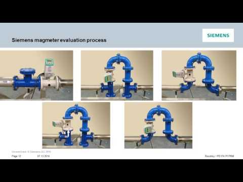
▶ Watch on YouTube: Using Magmeters in Zero Upstream and Zero Downstream Applications — covers grounding, pipe orientation, and installation requirements for electromagnetic flow meters in constrained spaces.
6. Output Signals, Communication Protocols, and Integration

A magmeter that measures accurately but cannot communicate its data into the client’s control system is an instrumentation dead end. Confirming communication protocol compatibility is a specification step that is routinely left to the commissioning engineer — and routinely costs $500–$1,500 per measurement point in protocol converter hardware when the meter and the control system turn out not to speak the same language.
O 4–20 mA analog output is the universal baseline — every PLC, DCS, SCADA input card, and data logger manufactured in the last 40 years can read it. It carries a single process variable (typically flow rate) and no diagnostic information. For simple monitoring applications and legacy control systems, it is fully adequate.
HART (Highway Addressable Remote Transducer — a digital signal superimposed on the 4–20 mA loop) enables two-way digital communication over the same two-wire loop: remote configuration, diagnostics, secondary variable transmission, and asset management from the control room — without additional wiring. For facilities that already have HART-capable DCS or SCADA infrastructure, HART is the most cost-effective path to advanced diagnostics. A single HART read covers flow rate, fluid velocity, empty-pipe status, electrode coating index, coil resistance, and transmitter temperature simultaneously.
Modbus RTU (over RS-485) is the most widely supported digital protocol in industrial automation globally — compatible with virtually every PLC platform including Siemens S7, Allen-Bradley, ABB, and Mitsubishi. Multi-drop RS-485 networks can connect up to 32 meters on a single cable pair, reducing wiring cost significantly on multi-point installations. Modbus TCP extends this over Ethernet to SCADA historians and cloud analytics platforms without a protocol gateway.
PROFIBUS PA is the standard fieldbus in European process plant DCS architectures (Siemens TIA Portal, ABB 800xA, Honeywell Experion). It provides full digital, multi-variable communication on a single intrinsically safe two-wire cable pair, eliminating marshalling cabinets on large projects.
Ethernet APL (Advanced Physical Layer) — the newest generation, delivering 10 Mbit/s two-wire Ethernet to the field device with intrinsic safety — is the future-proof choice for new plant construction. It enables web-based dashboards, remote firmware updates, and digital twin integration without a laptop visit to the field. For brownfield retrofits with established HART or Modbus infrastructure, the rewiring cost of APL migration is rarely justified until the next major plant upgrade. For reference on matching meter outputs to control system architectures, the Turbines Incorporated flow meter communication protocol guide covers 4–20 mA, HART, Modbus, and PROFIBUS comparison in practical terms.
| Protocolo | Physical Layer | Multi-Variable? | Remote Config? | Melhor para |
|---|---|---|---|---|
| 4–20 mA | Two-wire | Não | Não | Universal compatibility, legacy systems |
| Pulse/Frequency | Two-wire | Não | Não | Totaliser-based batch and billing |
| HART 7 | Overlay on 4–20 mA | Sim | Sim | Diagnostics, multi-variable, existing HART infra |
| Modbus RTU | RS-485 | Sim | Sim | Multi-drop PLCs, broad compatibility |
| Modbus TCP | Ethernet | Sim | Sim | SCADA historians, cloud analytics |
| PROFIBUS PA | Two-wire IS | Sim | Sim | DCS-centric European process plants |
| Ethernet APL | Two-wire Ethernet | Sim | Sim | New plant construction, digital twin ready |
O Jade Ant Instruments electromagnetic flow meter range supports configurable 4–20 mA, HART, and Modbus RS-485 outputs with user-selectable damping, low-flow cutoff, and onboard diagnostic reporting — covering the majority of industrial automation environments without protocol translation hardware.
7. Power Supply Options and Energy Efficiency
Power supply compatibility is a specification step that is easy to overlook in standard industrial applications — and critical in non-standard ones. For a skid-mounted chemical dosing system or a building-mounted HVAC application, 85–265 V AC universal supply is standard and unproblematic. For remote locations, the supply constraint is often the primary selection driver.
Battery-powered magmeters — specifically designed for water network monitoring where mains power is unavailable — are a genuine product category with real performance. Siemens’ SITRANS FM MAG 8000 and KROHNE’s WATERFLUX 3070 are both purpose-designed battery-operated meters for municipal water distribution monitoring, offering up to 15–20 years of battery life through duty-cycle measurement (logging flow at defined intervals rather than continuously). They support wireless data transmission via GPRS, NB-IoT, or LoRaWAN — feeding real-time flow data into utility network management systems without any physical cable infrastructure. For municipal utility clients managing remote pump stations, rural distribution mains, and district metered area inlets, battery-powered meters are the difference between deploying measurement where it is needed and deploying it only where power is available.
Low-voltage DC-powered meters (typically 12–36 V DC) are compatible with solar panel systems at remote monitoring sites — oilfield produced water management, mine site tailings dams, remote agricultural irrigation infrastructure — where grid power does not exist and generator running costs are prohibitive. For EPC firms specifying instrumentation for remote projects, the solar/battery power option on a flow meter eliminates the cable tray, cabling, junction boxes, and power distribution work that would otherwise be required for a mains-powered meter — a saving of $2,000–$8,000 per remote measurement point in installed cost.
For environmentally sensitive applications and ESG-reporting facilities, low-power transmitter designs (power consumption ≤2.5 W) contribute to Scope 2 emissions reduction at scale. Across a water utility running 200 flow meters continuously, the difference between a 10 W average-power meter and a 2.5 W low-power design is 7.5 W × 200 meters × 8,760 hours = 13,140 kWh per year — meaningful at carbon cost, and a genuine selling point for facilities under ISO 50001 energy management certification obligations.
8. Maintenance, Diagnostics, and Smart Features
The MRO team’s standard question about any piece of process instrumentation is: “What breaks, how often, and what does it cost to fix?” For electromagnetic flow meters, the honest answer is: almost nothing breaks — provided the original specification was correct. The measurement principle involves no moving parts, no wetted rotating components, no spring-loaded mechanisms, and no differential pressure cells. The primary failure modes are electrode coating (in fluids with high calcium or biological fouling potential), liner degradation (from chemical incompatibility or mechanical damage during installation), and transmitter electronics failure (typically after 10–15 years of continuous operation in demanding environments).
Modern magmeter transmitters include onboard diagnostic functions that transform the meter from a passive measurement device into an active asset health monitor. Empty-pipe detection (EPD) alerts the control system when the meter is not full of fluid — preventing false totalisation and protecting the transmitter from dry-running. Electrode coating index quantifies the electrical resistance buildup on the electrode surfaces before it affects accuracy, enabling proactive cleaning rather than reactive recalibration after the meter has already drifted outside specification. Coil resistance monitoring detects degradation in the magnetic field coils — a precursor to sensor failure that can be identified and scheduled for replacement during a planned shutdown rather than discovered during an unplanned one.
In-situ calibration verification — marketed under various brand names including Endress+Hauser’s Heartbeat Technology, Siemens’ SENSORPROM, and ABB’s SmartSensor — allows the transmitter to perform a self-verification sequence, comparing current performance against its factory calibration baseline, without removing the meter from service or interrupting the process. For food processing, pharmaceutical, and water utility clients subject to regulatory audit, an in-situ verification report generated quarterly provides continuous evidence of meter performance compliance — eliminating the annual “remove, send to lab, reinstall” calibration cycle that previously required process isolation.
For IoT-ready and Industry 4.0-aligned clients, the HART or PROFIBUS diagnostics data from a magmeter feeds directly into predictive maintenance platforms — OPC-UA enabled SCADA historians, cloud-based asset management tools, and digital twin models — that correlate meter health data with process variables to identify developing problems before they cause measurement failure. For an OEM skid builder whose client requests continuous remote monitoring of skid performance, the diagnostic outputs from a HART-enabled magmeter provide the data foundation for a service contract that generates recurring revenue long after the equipment sale closes. Jade Ant Instruments’ magnetic water flow meter maintenance guide provides practical maintenance intervals and diagnostic interpretation guidance for field technicians working across multiple meter brands and installation environments.
9. Total Cost of Ownership and Supplier Support
Purchase price is typically 25–35% of a magmeter’s 10-year total cost of ownership. Calibration, spare transmitter electronics, liner and electrode maintenance, and unplanned downtime cost — when quantified honestly — dominate the remaining 65–75%. For distributors building a commercially credible recommendation, presenting the 10-year TCO model rather than the unit price is the difference between winning on value and competing on margin.
A DN100 magmeter installed on a municipal wastewater line (hard rubber liner, 316L electrodes, 24/7 continuous operation) has the following 10-year cost structure:
| Categoria de custo | Premium Brand (e.g., E+H Promag) | Mid-Range Brand | Economy Brand |
|---|---|---|---|
| Purchase (meter + transmitter) | $3,500 | $2,200 | $1,200 |
| Installation (mechanical + electrical) | $800 | $800 | $800 |
| Calibration (3 intervals, 3-yr cycle) | $2,700 | $2,400 | $1,500 |
| Electrode / sensor maintenance | $500 | $500 | $600 |
| Spare transmitter board | $1,200 | $900 | $600 |
| Estimated unplanned downtime (10 yr) | $1,000 | $1,500 | $2,500 |
| 10-Year Total TCO | $9,700 | $8,300 | $7,200 |
The economy-brand meter has the lowest 10-year TCO in the municipal wastewater application — confirming that “buy cheap, pay more later” does not apply to well-specified, correctly installed electromagnetic flow meters in forgiving fluid environments. The premium brand’s diagnostic capability and self-verification reduce calibration cost and downtime risk — advantages that become decisive in chemical and pharmaceutical applications where a single unplanned measurement failure costs $10,000–$50,000. The right recommendation is not “buy the most expensive meter” or “buy the cheapest” — it is “match the meter’s capability level to the application’s risk level and the client’s maintenance philosophy.”
Supplier support quality is the non-quantifiable element that determines whether a distributor relationship delivers lasting value. The support attributes that matter most to the client segments described in this guide are pre-sale technical support (application engineering review, liner/electrode compatibility assessment, sizing calculations), calibration certificates with full traceability documentation, spare parts availability (not just list availability but actual stock in a regional distribution hub), and post-sale field support (the ability to send a technically qualified person to a commissioning problem, not a warranty claims process that requires three weeks of email correspondence).
10-Year TCO Breakdown — DN100 Wastewater Application

Purchase Price   ████████░░░░░░░░░░░░  36%
Calibration      ███████░░░░░░░░░░░░░  28%
Installation     ████░░░░░░░░░░░░░░░░  8%
Spare Parts      ████░░░░░░░░░░░░░░░░  18%
Downtime Risk    ███░░░░░░░░░░░░░░░░░  10%

Purchase price is less than 40% of what you will spend. Specify accordingly.
Instrumentos Jade Ant provides ISO 9001-certified electromagnetic flow meters across DN10–DN2000 with PTFE, hard rubber, ceramic, and polyurethane liner options, optional ±0.2% accuracy, and free pre-sale application-specific compatibility assessment. For OEM and EPC clients managing high-volume projects, OEM/ODM configuration — custom flange standards, private-label transmitters, non-standard communication protocol configurations — is available with project-specific lead time planning.
10. Sanitary, Hazardous, and Special-Duty Applications
Not every electromagnetic flow meter installation fits the standard industrial template of a flanged, mains-powered meter on a metallic pipeline in a non-classified area. Three application categories — sanitary/food-grade, hazardous area, and large-bore — require specific product attributes that must be confirmed at the specification stage.
Sanitary and food-grade applications in dairy, beverage, brewing, pharmaceutical, and personal care manufacturing require meters that comply with 3-A Sanitary Standards (North America) and EHEDG (European Hygienic Engineering and Design Group — the EU food-grade equipment design standard). The wetted parts — liner, electrodes, and body — must be FDA-compliant materials: PFA or PTFE liner, 316L stainless steel body, and electropolished internal surfaces with a roughness of Ra ≤ 0.8 µm to prevent microbial harbouring. Connections must be hygienic: Tri-Clamp (most common in North America), DIN 11851 (European dairy), or SMS 1145 (Scandinavian food). The meter must be fully drainable (no dead legs where product can be trapped between batches) and must survive CIP (Clean-in-Place) and SIP (Steam-in-Place) cycles — 130°C steam sterilisation with NaOH or peracetic acid cleaning agents. A standard industrial magmeter with a hard rubber liner and standard flanges installed in a dairy application will fail the first CIP audit. According to Soaring Instrument’s pharmaceutical flow meter guide, surface finish verification (electropolishing certification and Ra measurement records) is a documentation requirement for FDA cGMP facility qualification, separate from the meter’s functional performance specification.
Hazardous area installations in petrochemical, offshore, and chemical plant environments require ATEX (Europe, Ex-marked) or IECEx (international) certification on both the sensor and transmitter. The certification category (Gas Group IIA/IIB/IIC, Temperature Class T1–T6) must match the specific hazardous substance present in the classified area — not just “ATEX certified” as a generic claim. For SIL (Safety Integrity Level) applications where the flow measurement is part of a safety instrumented function, the meter must carry a SIL 2 hardware fault tolerance rating with documented PFD (Probability of Failure on Demand) data for inclusion in the SIF safety case. These are not supplier claims to be taken on faith — they require documentary evidence in the form of IECEx certification documents and SIL certificates from a TÜV or exida-approved assessment body.
Para large-bore applications above DN600, the cost difference between full-bore inline meters and insertion meters becomes commercially decisive. A full-bore DN1000 inline electromagnetic meter costs $25,000–$60,000 depending on liner and electrode specification. An insertion electromagnetic meter with a hot-tap fitting on the same DN1000 pipe costs $4,000–$8,000 — 80–85% less — at the cost of accuracy downgrade from ±0.2% to ±1–2%. For a raw water intake line on a municipal treatment plant where ±2% accuracy is fully acceptable for operational flow monitoring (billing accuracy is handled by a smaller, downstream custody transfer meter), the insertion meter at $6,000 installed is a completely defensible recommendation. Presenting this option to a client who was budgeting for a $45,000 inline meter demonstrates exactly the kind of value-added advisory role that builds long-term distributor relationships.
Glossário de termos-chave
Conductivity (µS/cm): A measure of a fluid’s ability to carry electrical current. Electromagnetic flow meters require ≥5 µS/cm. Most industrial liquids — water, acids, caustics, slurries — comfortably exceed this. Hydrocarbons, pure alcohols, and organic solvents do not.
EMI (Electromagnetic Interference): Electrical noise from VFDs, welding equipment, or nearby power cables that contaminates the millivolt-level signal in a magmeter. The primary cause of the 50% grounding-related failure rate in field service data. Prevented by correct grounding, grounding rings on non-conductive pipes, and signal cable separation.
EPD (Empty-Pipe Detection): A built-in transmitter function that detects when the pipe is not full of liquid. Prevents false totalisation and protects the transmitter from operating in air.
Faraday’s Law of Electromagnetic Induction: The physics principle underlying magmeters. A conductive fluid moving through a magnetic field generates a voltage proportional to its velocity. No moving parts, no obstruction in the flow path.
Grounding Ring: A conductive metal ring installed on the meter flange on non-metallic pipelines, creating a direct electrical connection between the process fluid and the plant’s earthing system. Cost: typically $80–$200 per ring. Value: eliminates the primary failure mode responsible for 50% of all magmeter field complaints.
HART (Transdutor Remoto Endereçável por Roteira): A communication protocol that superimposes a 1.2 kbps digital signal on the standard 4–20 mA loop, enabling two-way communication — remote configuration, diagnostics, and multi-variable data — without additional wiring.
In-Situ Verification: A transmitter self-test function that compares current meter performance against the factory calibration baseline without removing the meter from service. Eliminates the process isolation required for physical recalibration in many applications.
ISO 17025: The international standard for testing and calibration laboratory competence. A calibration certificate issued by an ISO 17025-accredited lab, referencing NIST or equivalent national metrology institute standards, provides the traceability documentation required for regulatory compliance audits.
Liner: The inner surface of a magmeter flow tube, chemically isolated from the outer carbon steel body. Material selection — rubber, PTFE, PFA, polyurethane, ceramic — determines chemical compatibility, abrasion resistance, temperature rating, and service life.
SIL (Safety Integrity Level): A reliability classification (SIL 1–4) for safety instrumented functions. SIL 2-rated flow meters carry certified probability of failure on demand data for use in formal safety cases under IEC 61508 and IEC 61511.
Turndown Ratio: The ratio of maximum to minimum measurable flow rate at the meter’s rated accuracy. A 100:1 turndown means a meter rated to 10 m/s velocity reads accurately down to 0.1 m/s — essential for applications with wide seasonal or batch-cycle flow variation.
The 7-Step Specification Checklist
Before any electromagnetic flow meter purchase order is placed, seven questions must be answered with documented specificity rather than assumed from application category:
Step 1 — Define the fluid: Confirm conductivity, chemical composition (including trace compounds), temperature range, and suspended solids content. If conductivity is below 5 µS/cm, a magmeter is not the correct technology.
Step 2 — Select the liner: Cross-reference the specific chemical and temperature against the manufacturer’s chemical resistance table. Never assume one fluoropolymer is interchangeable with another. Confirm vacuum-service rating if the process cycles between vacuum and positive pressure.
Step 3 — Select the electrode material: Start with 316L for water, move to Hastelloy C-276 for mixed acids and chlorinated media, titanium for seawater and hypochlorite, tantalum for hot concentrated acids, Pt-Ir for custody transfer and pharmaceutical API dosing.
Step 4 — Size the meter correctly: Calculate flow velocity at normal operating rate. Downsize one DN class if velocity falls below 1 m/s. Consider insertion type if bore exceeds DN400 and ±2% accuracy is acceptable.
Step 5 — Verify installation space: Confirm straight-run availability (5D upstream, 2–3D downstream as minimum), pipe orientation (avoid horizontal installation with air pocket risk), and access for the grounding rings required on non-metallic pipelines.
Step 6 — Specify the communication protocol: Confirm the client’s DCS or SCADA input card type before ordering. Confirm whether ATEX or IECEx certification is required. Confirm power supply availability and voltage.
Step 7 — Model the 10-year TCO: Include calibration intervals, spare transmitter cost, liner/electrode service life, and estimated downtime cost. Compare at least two brands on the TCO model, not on purchase price alone.
Application Case Studies
A 150 MLD municipal water treatment plant in Shandong Province installed 34 magmeters across raw water intake, coagulant dosing, filter backwash, and treated water distribution points. After 18 months, the plant reported zero unplanned meter outages and a 12% reduction in coagulant consumption attributable to more accurate dosing enabled by ±0.2% accuracy meters on the chemical feed lines. Annual chemical savings: approximately $52,000. The payback on the six dosing meters at $3,000 installed each was under 5 months.
A specialty chemical manufacturer in Jiangsu Province processing 15% hydrochloric acid through a DN80 meter switched from Hastelloy C-276 electrodes — which showed pitting at 22 months — to tantalum electrodes. A 36-month inspection of the tantalum installation showed no measurable corrosion. The same plant specified ceramic-lined magmeters on its titanium dioxide slurry lines after polyurethane liners at the same measurement points lasted only 8 months. The ceramic installations exceeded 4 years of service without liner replacement.
A water utility managing 12 district pumping stations replaced turbine meters generating $21,000 per year in combined maintenance costs with clamp-on and inline magmeters. First-year maintenance expenditure across all 12 stations: $3,200. The $17,800 annual saving paid back the $68,000 retrofit investment in under four years — before accounting for the operational intelligence gained from continuous pump performance data that the turbine meters could not provide.
Further Resources
Electromagnetic Flow Meter Selection Guide: Liner, Electrode & Sizing — Jade Ant Instruments →
Top 10 Magnetic Flow Meter Applications: Industry-Specific Performance Data →
Magnetic Water Flow Meter Maintenance Guide — Field Servicing and Calibration →
Common Flow Meter Specification Mistakes That Cost Distributors Money →
Contact the Jade Ant Instruments Engineering Team for a Free Application Assessment →
Perguntas frequentes
What is the minimum fluid conductivity required for an electromagnetic flow meter to work? Most commercial magmeters require a minimum conductivity of ≥5 µS/cm. Municipal tap water (300–800 µS/cm), most industrial acids and bases (1,000–100,000 µS/cm), and slurries all comfortably exceed this threshold. Deionised water below 1 µS/cm and hydrocarbon oils cannot be measured by standard magmeters. Some specialised high-sensitivity models claim operability down to 0.5–1 µS/cm for ultrapure water applications, but these require pre-confirmation with the specific manufacturer.
Can electromagnetic flow meters measure non-conductive fluids like oils or gases? No. The measurement principle requires an electrically conductive fluid to generate the flow-proportional voltage. For non-conductive liquids (hydrocarbons, alcohols, solvents), Coriolis or ultrasonic meters are the correct technology. For gas measurement, vortex, thermal mass, or ultrasonic meters are appropriate. Recommending the correct technology for non-conductive fluids — rather than attempting to force a magmeter specification — is itself a trust-building act with technically competent clients.
How much straight pipe run is required before and after a magmeter? Standard industrial magmeters require 5D upstream and 2–3D downstream of any flow disturbance — elbow, pump, valve, or reducer. Some models with integrated flow conditioners or specific compact designs are validated for 3D upstream. A small number of models — specifically KROHNE’s OPTIFLUX 2300 with OIML R49 approval and Siemens’ MAG 5100 W with MID MI-001 approval — are validated for 0D/0D installation in certain configurations. Always verify against the specific model’s installation manual rather than applying a generic standard.
What is the difference between inline and insertion electromagnetic flow meters? An inline meter is a full-bore spool piece installed in the pipeline — the fluid flows entirely through the meter body. It provides the highest accuracy (±0.2–0.5% of reading) and is the standard for applications requiring billing accuracy, dosing control, or regulatory compliance. An insertion meter is a probe inserted through a fitting in the pipe wall — it samples the flow profile at one or two points rather than across the full cross-section. It achieves ±1–2% accuracy, costs 60–80% less than an inline meter in large pipe sizes, and installs without full pipe isolation in hot-tap configurations. For DN400+ monitoring applications where ±2% is acceptable, insertion is the commercially superior specification.
How do I choose between flanged, wafer, and threaded connections? Flanged connections (ANSI, DIN, JIS) are the standard for industrial applications above DN25 — they are the most robust, the easiest to inspect and replace, and the most widely supported by piping systems in process plants, utilities, and OEM skids. Wafer connections (compressed between flanges, no independent bolting) are used in space-constrained skid applications where reducing installation envelope is a design priority; they are slightly more challenging to remove for maintenance. Threaded connections (BSP, NPT) are standard for small-bore meters below DN25 in lab, HVAC, and residential water metering applications. For food and pharmaceutical service, tri-clamp and DIN 11851 hygienic connections replace standard flanges.
Are electromagnetic flow meters suitable for sanitary or food-grade applications? Yes — but only meters specifically designed and certified for sanitary service. Standard industrial magmeters do not meet sanitary requirements. Sanitary magmeters must carry 3-A Sanitary Standards certification (North America) or EHEDG approval (Europe), use FDA-compliant PFA or PTFE liners and 316L stainless steel wetted parts, have electropolished internal surfaces to Ra ≤ 0.8 µm, and connect via Tri-Clamp or DIN 11851 hygienic fittings. They must survive CIP/SIP cycles at 130°C steam sterilisation temperature. Specifying a standard industrial magmeter in a dairy or pharmaceutical application is a compliance failure, not just a performance issue.
Can magmeters handle slurries or abrasive fluids? Yes — the full-bore, obstruction-free design is one of the magmeter’s strongest advantages in abrasive service. No impellers or probes to wear. Liner selection is the critical variable: polyurethane provides good abrasion resistance for moderate slurry service up to 50°C; ceramic (Al₂O₃, ~1,700 HV Vickers hardness) provides outstanding abrasion resistance for high-solids mining and cement applications. Solids concentrations exceeding 40% by weight are routinely measured by correctly specified magmeters — the key constraint is minimum fluid conductivity, which must still be ≥5 µS/cm in the continuous liquid phase of the slurry.
What happens if the pipe is not full? Will the meter still read accurately? No. A standard magmeter requires a completely full pipe for accurate measurement. If the pipe runs partially full — common in gravity-flow drainage channels, partially-emptied filling lines, or systems operating below their minimum design flow rate — the meter will over-report flow because it assumes a full-bore fluid cross-section in its calculation. The correct solution is to install the meter at a low point in the pipeline or in a vertical section with upward flow, and to configure the empty-pipe detection (EPD) alarm to alert the control system when partial-fill is detected. For genuine open-channel or partial-fill applications, a purpose-built area-velocity meter or flume-based flow measurement system is the appropriate technology.
How often do electromagnetic flow meters need calibration? In stable industrial service, 2–3 year calibration intervals are standard for process monitoring and control applications. Annual calibration is required for custody transfer, billing, and regulatory compliance applications regardless of the meter’s intrinsic stability. In-situ verification tools (Endress+Hauser Heartbeat Technology, Siemens SENSORPROM, ABB SmartSensor) generate a verification report without removing the meter from service — satisfying audit requirements for many regulated applications between full laboratory calibrations. The ATS flow meter calibration guide explains the distinction between calibration and verification and the documentation each provides for compliance purposes.
Can I retrofit an electromagnetic flow meter into an existing system? Yes — in most cases. The retrofit options are: (1) replace an existing spool piece inline meter with a magmeter of the same flange standard — a direct swap if the pipe size matches; (2) install an insertion magmeter through a hot-tap fitting on the existing pipe, requiring no process shutdown and no pipe modification beyond the hot-tap; (3) use a compact wafer-style magmeter where a full flanged spool piece would not fit in the available space. The constraint that eliminates options (1) and (3) is available straight-run on the existing pipeline — if the current meter location has inadequate straight-run due to its proximity to elbows or valves, the retrofit may need to relocate to a better position rather than installing in the same location.
What certifications should I look for when selling into regulated industries? For drinking water applications: NSF/ANSI 61 (materials in contact with potable water) and OIML R49 or MID MI-001 for metrological approval. For hazardous areas: ATEX (Zone 1/2, Europe) or IECEx (international equivalent), with the correct Gas Group and Temperature Class for the specific hazardous substance. For safety instrumented functions: SIL 2 certification with PFD data. For food/pharma: 3-A Sanitary Standards (North America) or EHEDG (Europe) with FDA-compliant materials declaration. For oil and gas custody transfer: API MPMS Chapter 5 (liquid hydrocarbons). For CE-marked equipment in the EU: MID (Measuring Instruments Directive) for meters used in regulated trade measurements. Always request copies of the original certification documents — not just datasheet claims — before quoting for a regulated application.
How does temperature affect electromagnetic flow meter performance? Temperature affects both the liner and the measurement electronics. Each liner material has a rated maximum operating temperature: hard rubber to 80°C, polyurethane to 50°C, PTFE and PFA to 150–180°C, ceramic to 180°C+. Exceeding the liner temperature rating causes irreversible deformation or delamination. The electronics rating (typically –20°C to +60°C ambient) must cover the installation environment, not the process temperature — the two are different in remote outdoor installations where ambient can reach –30°C in winter and +50°C in summer. Transmitters can be remote-mounted up to 10–30 metres from the sensor on a signal cable, positioning the electronics in a climate-controlled panel while the sensor handles the process temperature. For high-temperature process applications above 150°C, confirm with the manufacturer whether the transmitter requires remote mounting.
Is bidirectional flow measurement possible with an electromagnetic flow meter? Yes — bidirectional measurement is inherent to the operating principle. When the fluid reverses direction, the polarity of the induced voltage reverses, and the transmitter detects this automatically without any additional hardware. Forward and reverse totals are accumulated in separate registers, and reverse flow can be indicated on the local display and transmitted via all standard output protocols. This capability is particularly valuable in CIP systems (where cleaning solution flows forward through the process line and returns via the same pipe), district heating and cooling loops (where pump trips can cause reverse flow transients), and water distribution networks (where valve switching generates bidirectional flow events that must be included in the volume record for regulatory reporting).
What technical support should I expect from a manufacturer as a distributor partner? At minimum: pre-sale application engineering support (liner/electrode compatibility assessment, pipe sizing calculation, protocol selection guidance), calibration certificates with NIST-traceable reference standard documentation for every shipped meter, comprehensive installation and commissioning documentation in the relevant language, and post-sale technical support accessible by phone or email within one business day. Leading manufacturers also provide technical training programmes for distributor application engineers, marketing materials for client-facing presentations, online product selection and sizing tools, and regional stock of fast-moving spare parts. The quality of this support infrastructure is what determines whether a distributor can confidently recommend a product to a technically demanding EPC or OEM client — or must constantly escalate questions back to the manufacturer while the client waits.
Sources and further reading:
- Electromagnetic Flowmeter Market Report — Mordor Intelligence
- What Causes Errors in a Magnetic Flow Meter — Soaring Instrument 2024 Field Analysis
- Magmeter Grounding Technical Note — Emerson Automation Solutions
- Flow Meter Calibration Standards and NIST Traceability — Kobold USA
- Flowmeter Calibration Best Practices — ATS Laboratory
- Flow Meter Communication Protocols Explained — Turbines Incorporated
- Pharmaceutical Flow Meter Sanitary Design and FDA Compliance Guide — Soaring Instrument
- Jade Ant Instruments Electromagnetic Flow Meter Selection Guide