Clamp-On Ultrasonic Flow Meters: Measure Flow Without Cutting the Pipe
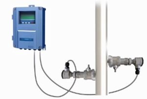
A clamp-on ultrasonic flow meter reads flow through the pipe wall. You do not cut the pipe. You do not drain the line. You do not stop the process.
On a DN100 water main, the meter costs about USD 3,400. The shutdown you avoid often costs more than that. This guide covers how the technology works, where it fails, and how to specify it for your own line.
The shutdown problem clamp-on meters solve
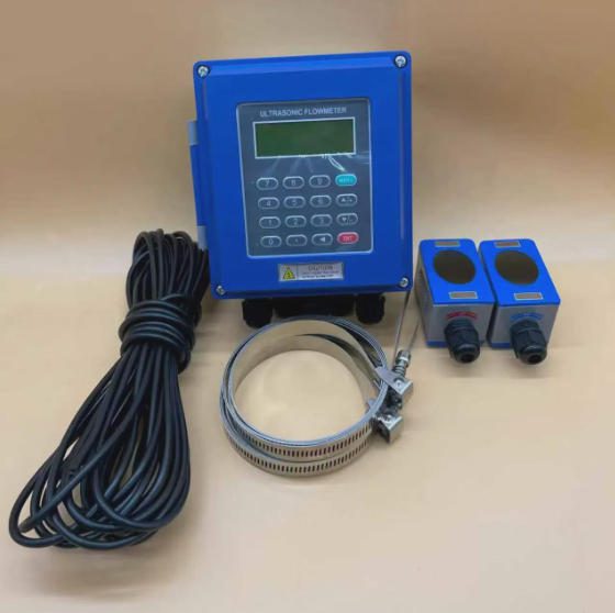
Quick definition: a clamp-on ultrasonic flow meter is a flow meter whose sensors sit on the outside of a pipe. The sensors send sound through the pipe wall and read the flow from the sound that comes back.
Traditional meters go inside the pipe. That means a spool piece, two flanges, a weld, a pressure test, and an outage. For a 6-inch line, a careful crew needs 4 to 8 hours on site before permits and restart checks. Multiply those hours by what the line earns.
One simple formula helps you judge the job:
Shutdown cost = hours stopped × lost output per hour.
Take a plant that loses USD 5,000 of output per hour. A 4-hour stop costs USD 20,000 before the meter reads a single number. The meter itself may cost USD 3,000.
Cutting a pipe also adds risk that never shows on a quote. Every new flange is a new place to leak. On hot, high-pressure, or hazardous lines, that risk stays with the plant for 20 years.
Jade Ant Instruments sells to five kinds of buyers, and each one feels this problem differently. OEM and skid-mount manufacturers lose margin to welding hours. Instrument distributors and importers lose deals when a customer cannot take an outage.
EPC and system integrators carry the commissioning schedule. Industrial terminal and MRO teams need answers without draining a line. Municipal and utility companies cannot interrupt supply at all.
How a clamp-on ultrasonic flow meter reads flow from outside the pipe
Two methods do the work. One suits clean liquids. The other suits liquids that carry solids or bubbles. Getting this choice right is most of the specification.
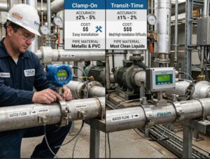
Transit-time is the first method. Two transducers send a pulse with the flow and one against it. Sound moving with the water arrives sooner.
The meter measures that gap in nanoseconds, and the gap is proportional to velocity. Flow then follows from pipe area: Q = A × v.
An example makes it concrete. A DN200 pipe has an inner area of about 0.0314 m². At 1.5 m/s, the flow is 0.0314 × 1.5 = 0.047 m³/s, or about 170 m³/h.
Doppler is the second method. It bounces sound off particles or bubbles and reads the change in frequency. It works in dirty water, slurry, and mixed flows. It does not work in clean water, because there is nothing to reflect the sound.
The path pattern is the third decision. The meter fires the signal in a W, V, or Z shape. W suits small pipe, V suits mid-size pipe, and Z suits large pipe where the signal must cross once in a straight line.
| Your liquid | Best method | Precisão típica | Main risk |
|---|---|---|---|
| Clean water, glycol, light oil | Transit-time | ±1% of reading, single path | Air bubbles in the line |
| Wastewater, slurry, pulp stock | Doppler | ±2% to ±5% of reading | Too few solids to reflect |
| Both, on one site | Dual-mode meter | Depends on the mode used | Wrong mode selected |
One number decides more than the electronics. A 1 mm error in measured pipe diameter can push volume flow error past 3%. Measure the outside diameter with a tape and the wall thickness with an ultrasonic gauge. Do not copy a wall thickness from a drawing.
The path pattern also sets accuracy. Read this short comparison of transit-time versus Doppler meters before you fix the model, because the two are not interchangeable on the same line.
Pipe material decides whether the signal gets through
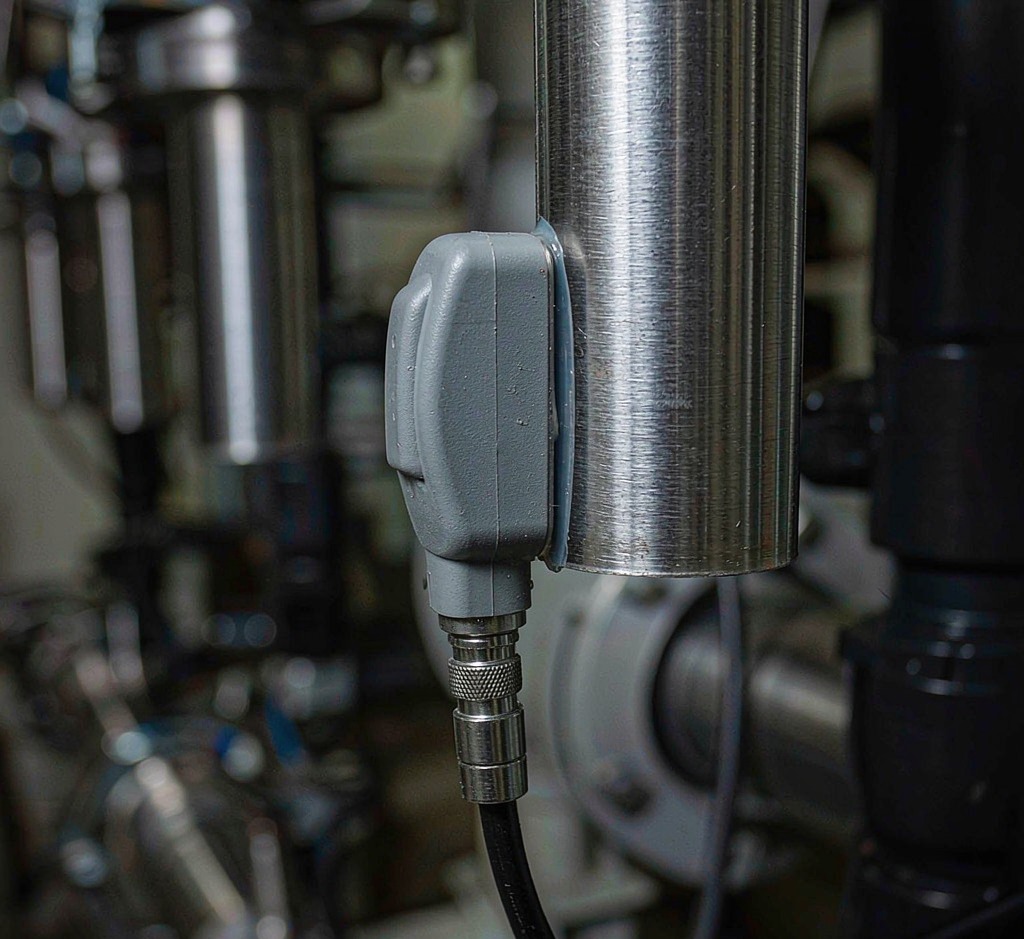
The pipe wall is part of the sound path. So the wall decides how much signal reaches the liquid and how much comes back.
Carbon steel is the common case, and it is friendly. Sound travels at about 3,200 m/s in steel, which is fast and predictable. Mill scale, paint, and bitumen coating are the usual problems. They trap air, and air kills the signal.
Stainless steel is the easiest metal. The surface is smooth, the wall is often thin, and the signal stays clean. Sanitary and high-purity lines are a good fit.
Cast iron and ductile iron are harder. The wall is thick and rough, and the outer surface may be graphitized. Use a lower frequency transducer and a Z path. Clean down to bare metal before you mount.
Plastic pipe gives a strong signal. PVC, HDPE, and GRP all carry sound well. The catch is dimensional tolerance. HDPE wall thickness varies along the pipe, and the pipe also changes shape under pressure. Measure at the exact spot where the transducers sit.
| Pipe material | Typical wall | Intensidade do sinal | What to watch |
|---|---|---|---|
| Carbon steel | 4–12 mm | Ótimo | Paint, scale, and rust under the sensor |
| Stainless steel | 2–6 mm | Very good | Thin wall plus high flow can clip the signal |
| Cast or ductile iron | 8–25 mm | Fair | Rough surface, use low frequency and a Z path |
| PVC, HDPE | 3–15 mm | Very good | Wall tolerance, liner, and pipe deflection |
Lined pipe needs one extra check. A bonded rubber or epoxy liner is fine when it touches the wall with no air gap. A loose liner breaks the sound path. The same rule applies to concrete or GRP pipe with a liner. If the pipe sounds dull when you tap it, stop and check the bond.
Jade Ant Instruments builds clamp-on ultrasonic flow meters for steel and plastic pipe from DN15 to DN6000. The transducer sets are matched to wall thickness, not just to pipe size.
Fluids that work, and fluids that break the reading
Ultrasonic meters do not care about electrical conductivity. That single fact decides many projects.
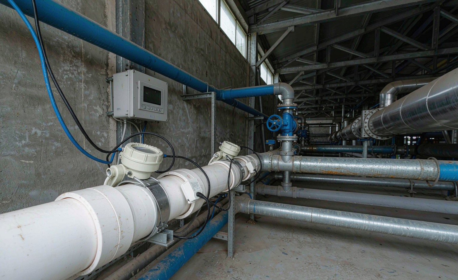
Magnetic flow meters need a conductive liquid, usually above 5 µS/cm. Deionized water, demineralized water, alcohols, glycols, and most oils fall below that line. Ultrasonic meters read them without trouble. This is why boiler makeup lines, CIP skids, and heat transfer loops often end up with a clamp-on meter.
Clean liquids are the easy case. Two conditions still hurt transit-time readings. Free gas above about 1% to 2% of volume scatters the signal. Heavy solids loading does the same. In both cases the meter drops out or reads low.
Slurries need the Doppler method, or a dual-mode meter that switches between methods. Abrasive slurry also wears an inline meter from the inside. A clamp-on sensor never touches the slurry, so wear stops being a maintenance item.
Temperature is the next limit. Standard clamp-on transducers cover about -40 °C to +200 °C. Above that, you need high-temperature probes and often a cooling standoff. Pressure matters less, because nothing enters the pipe. The wall carries the load, and the sensor only listens.
High-viscosity fluids such as heavy oil or polymer melt damp the sound. Signal strength drops, and accuracy drops with it. Ask for a low-frequency transducer and expect a shorter distance between sensors.
O ISA instrumentation standards group publishes the loop and signal conventions most plants still use. It is a useful reference when you write the specification.
Why OEMs and skid builders fit fewer welds
A skid is a sum of hours. Welding, testing, and paperwork are where those hours go.
A clamp-on meter removes parts from the bill of materials. No flanges. No spool piece. No tapped holes. No gaskets.
Each removed weld also removes a radiograph, a pickling pass, and a pressure-test point. On a skid with six flow points, that can take days out of the build.
Quick definition: BOM, or bill of materials, is the full parts list a skid is built from. Every line on it carries cost, lead time, and inspection.
The design also stays flexible. A sensor can move 2 m down the pipe in an afternoon. If a customer changes the pipe route, the meter follows. An inline meter would need a new spool.
Distributors and importers get a second benefit. One meter body covers many pipe sizes, so stock is simpler. A single unit can serve a DN80 line today and a DN150 line next month, with a different transducer set.
Jade Ant Instruments supports OEM flow accuracy support with factory-set pipe libraries. A skid builder can ship a meter that is already configured for the pipe it will sit on.
Commissioning without an outage: the EPC view
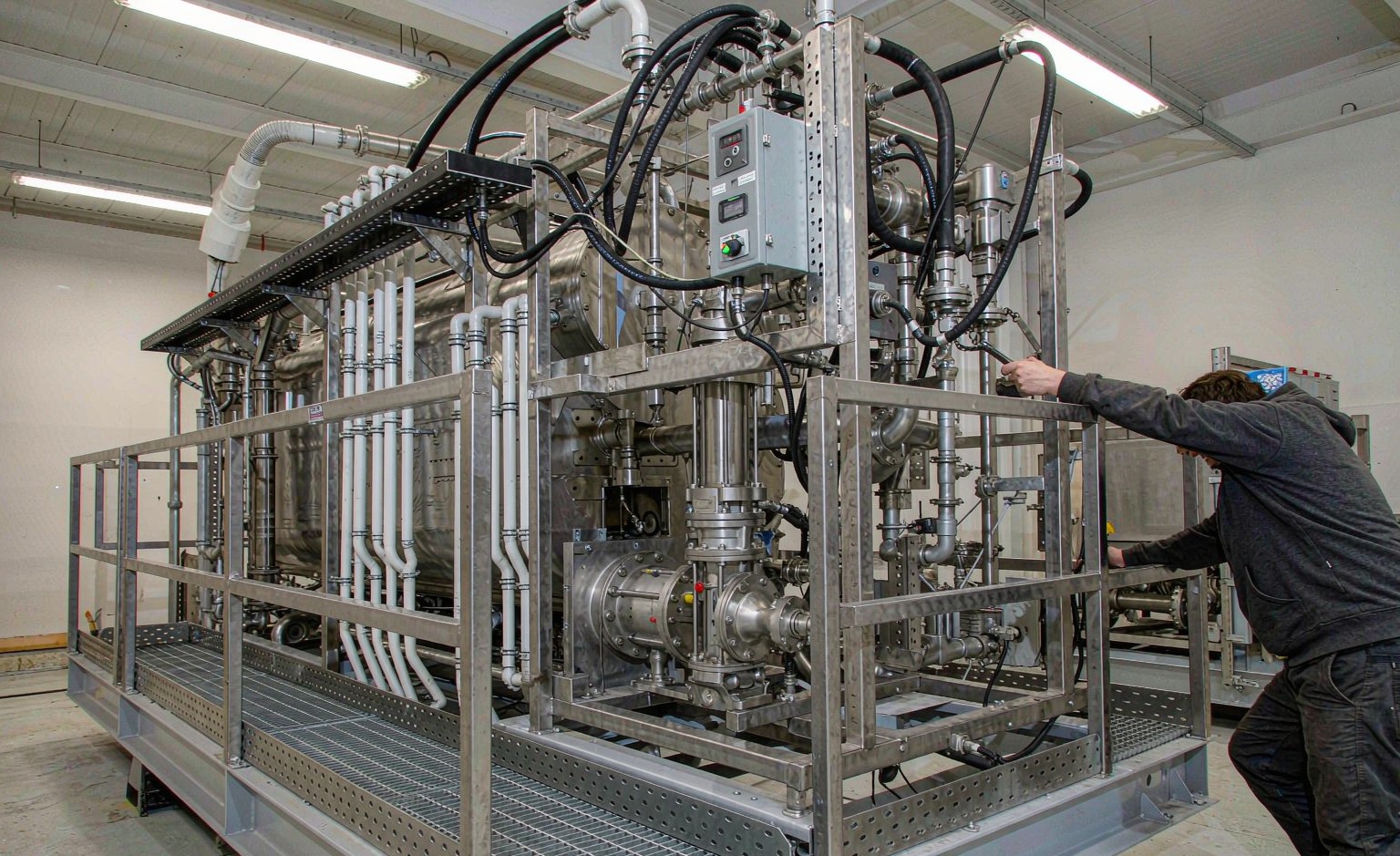
Commissioning is where schedules slip. A clamp-on meter moves most of that work into one visit with no outage window.
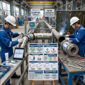
Five steps cover a normal installation:
- Pick a straight run. Allow 10 pipe diameters upstream and 5 downstream. Stay away from pump outlets, valve exits, and elbows.
- Measure the pipe. Record outside diameter to 1 mm, wall thickness with an ultrasonic gauge, and the material.
- Enter the data. The transmitter calculates transducer spacing and the path pattern.
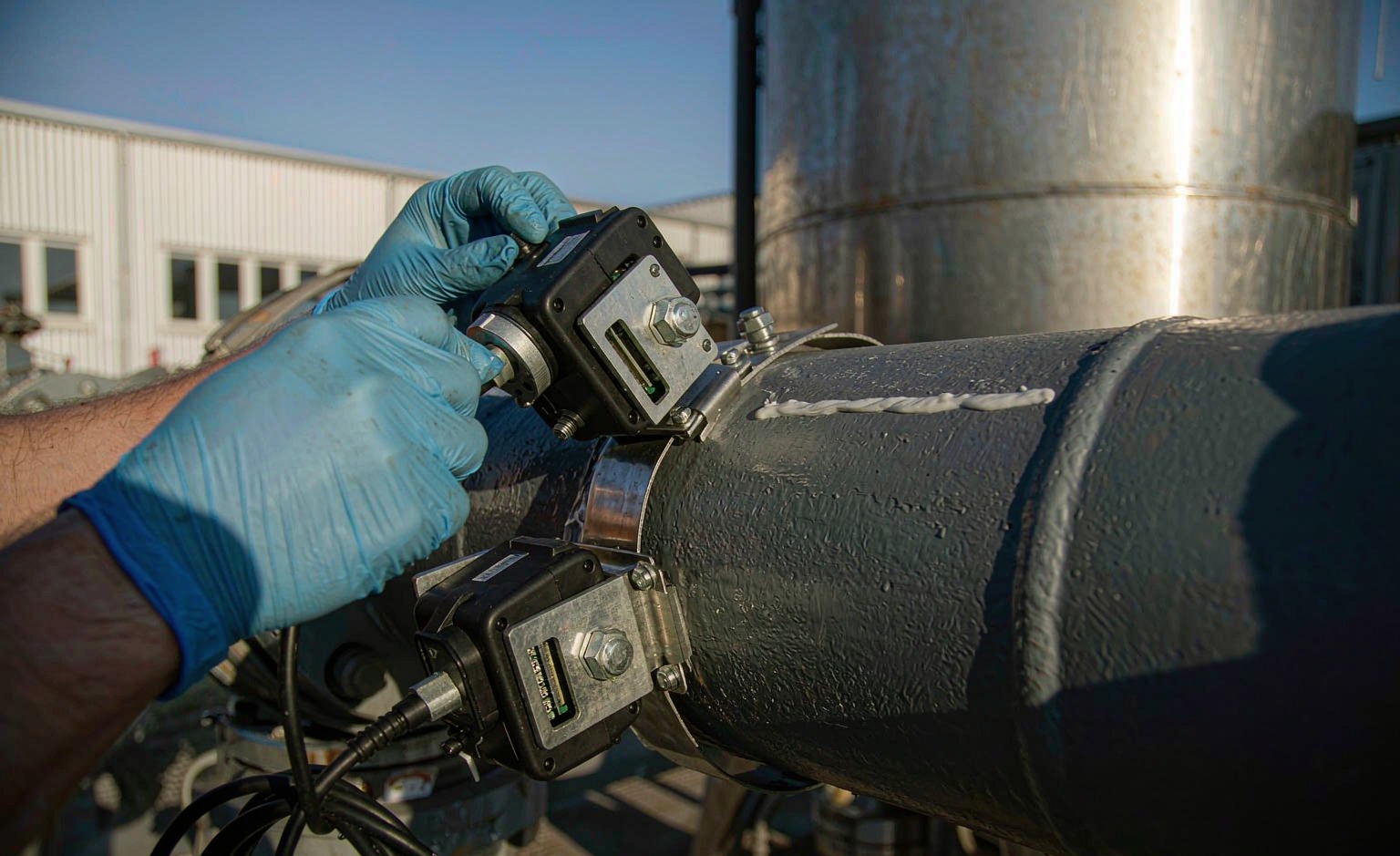
- Mount the sensors. Clean to bare metal, apply coupling gel 2 to 3 mm thick, and set the spacing the meter gave you.
- Check the signal. Aim for strength above 60%, quality above 60%, and a transit-time ratio near 100%.
A retrofit follows the same steps. That is the point. You can add flow data to a 20-year-old header without touching the process.
The output side is usually simple. Most plants want one analog signal and one digital link.
| Output | Best for | Typical use |
|---|---|---|
| 4–20 mA | Legacy PLC and DCS cards | Instant flow to a control room |
| Pulse | Totalizers and batch counters | Volume tracking and billing |
| Modbus RTU | Low-cost multi-drop networks | Several meters on one cable |
| HART | Setup over the existing loop | Configuration and diagnostics |
Modbus register maps come from the Modbus Organization, so point mapping stays predictable for an integrator. For plant-wide work, EPC integration planning covers tagging, loop drawings, and handover packs.
This short video shows the physical mounting better than any drawing. Watch where the technician places the transducers and how the straps sit on the pipe.
https://www.youtube.com/watch?v=A1ioGxeKzjI
What utilities gain: fewer invisible leaks, cleaner bills
In a water network, the meter is often the only witness. When it drifts, water disappears and nobody complains.
Clamp-on meters let a utility meter a district boundary or a trunk main without digging. The main stays live. Supply continues. A crew can install on a Tuesday morning and leave before lunch.
Battery-powered units make temporary district metering practical. You can compare two boundaries for a month, find the gap, and move the meter to the next zone. A fixed inline meter cannot follow that schedule.
Durability follows from the design. Nothing sits in the flow, so there is no impeller to foul, no electrode to coat, and no liner to fail. The parts that do age are the cable, the gel, and the electronics housing.
The energy side is quieter but real. An inline meter adds pressure drop that the pumps must overcome every hour of the year.
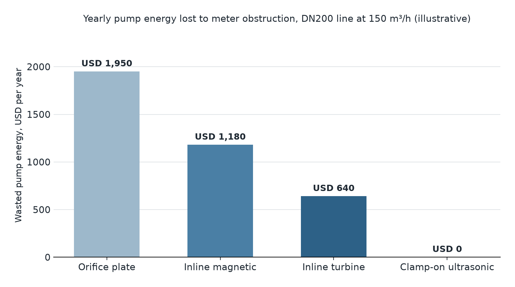
Those figures are illustrative. The ranking is not. A clamp-on meter adds no obstruction, so that column stays at zero, and the saving repeats every year. See how water and wastewater metering teams apply this to trunk mains and treatment plants. The AWWA water loss control resources cover the audit side, which is where the numbers usually start.
Maintenance for MRO teams: no wetted parts, no wear
A clamp-on meter has nothing to wear out in the flow. That changes the maintenance plan from replacement to verification.
The most common failure is not electronic. Coupling gel dries, cracks, or washes away. The reading drifts slowly, and nobody notices for months. Re-gel the sensors during the annual check, and the problem disappears.
The second common failure is movement. A sensor slides 5 mm on a hot pipe, the spacing changes, and the reading shifts. Mark the position with a paint pen at installation.
Troubleshooting follows the signal, not the display:
- A reading that falls to zero usually means air, a dry gel layer, or a sensor knocked loose.
- A steady bias usually means a wrong wall thickness or a wrong pipe material in the setup.
- A noisy reading usually means pump vibration or a pipe that is not running full.
Calibration is easier than most teams expect. You can compare against a portable clamp-on meter on the same pipe, or run a zero check with the line stopped and full. Neither job breaks the pipe seal. These field calibration and troubleshooting steps cover the checks in order, so a technician can clear the simple causes first. Jade Ant Instruments also ships replacement transducers and gel kits for units already in service.
Clamp-on versus inline: the trade-off in numbers
Both meters can be right. The decision turns on accuracy class, cost, and risk.
Inline meters still win on accuracy. A spool-piece ultrasonic or Coriolis meter reaches ±0.5% or better, and custody transfer usually demands it. A single-path clamp-on meter sits near ±1%. A dual-path clamp-on unit can reach ±0.5% to ±1% with good installation.
Cost moves the other way. The chart below compares one flow point on a DN100 water line over five years.
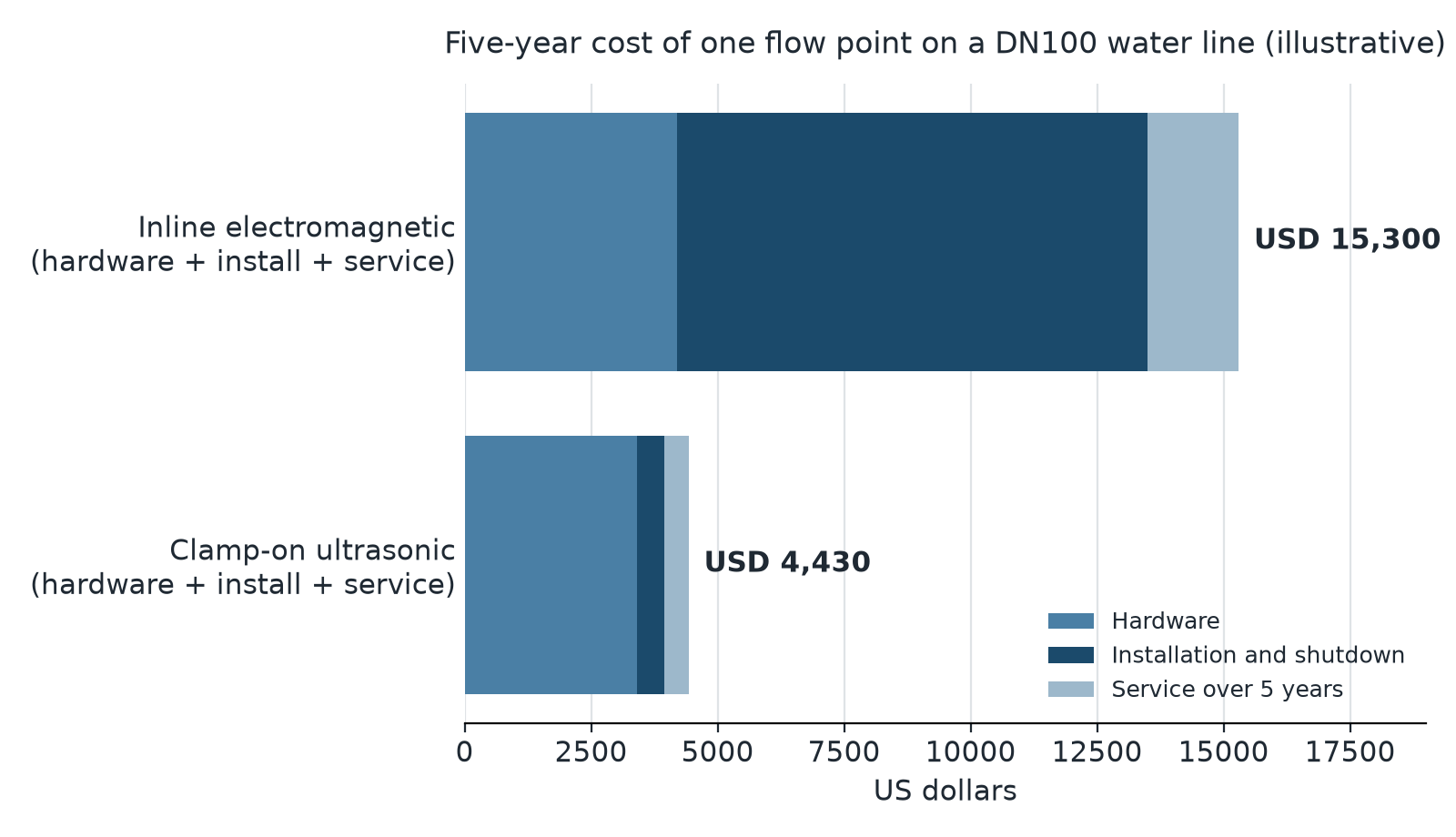
Those numbers are illustrative, built from typical hardware prices and a 4-hour outage. The shape holds on most brownfield sites: the meter price gap is small, and the installation gap is not.
Risk is the third column, and it is the one buyers forget. An inline meter adds two flanges, two gaskets, and a weld to a line that was already leak-tight. A clamp-on meter adds none.
| Decision factor | Clamp-on ultrasonic | Inline meter |
|---|---|---|
| Accuracy, typical | ±1% single path, ±0.5% dual path | ±0.5%, better with calibration |
| Installation time | 1–2 hours, no outage | 4–8 hours plus an outage |
| Pressure drop | Zero | Present, permanent |
| Leak points added | Nenhum | Two flanges per meter |
| Pipe size range | DN15 to DN6000 | Limited by spool availability |
| Transferência de custódia | Rarely accepted | Standard choice |
For a full side-by-side with sizing notes, read the clamp-on versus inline comparison before you lock the datasheet. The Hydraulic Institute also publishes pump efficiency guidance that helps you put a number on pressure drop.
Choosing non-invasive measurement with clear eyes
Clamp-on technology is not a compromise meter. It is a different trade. You give up a small amount of accuracy and some straight-run space. You get zero downtime, zero pressure drop, and no new leak points.
The fit is clearest in four cases. The line cannot stop. The pipe is large enough that an inline meter becomes expensive. The fluid would damage a wetted sensor. Or you need flow data on a pipe that was never designed for a meter.
Start with the pipe, not the price list. Material, outside diameter, wall thickness, fluid, temperature, and flow range decide the model. Get those six right and the rest is configuration.
Send us your pipe outside diameter, wall thickness, material, fluid, and expected flow range. We will confirm the transducer set and the mounting pattern for your line. We will also tell you if clamp-on is the wrong answer for it.
Terms You Should Know
| Termo | Plain meaning | Example |
|---|---|---|
| Fixação | A meter mounted on the outside of a pipe | Strapped to a DN300 main, no cut |
| Transducer | The sensor that sends and receives sound | Two units, one upstream, one downstream |
| Transit-time | Timing sound with the flow and against it | Reading clean cooling water |
| Doppler | Reading the frequency shift from moving particles | Reading wastewater with solids |
| V, Z, W path | How many times the sound crosses the pipe | Z path on a DN600 header |
| Coupling gel | Paste that carries sound between sensor and pipe | 2–3 mm layer, renewed each year |
| Straight run | Undisturbed pipe before and after the meter | 10D a montante, 5D a jusante |
| Relação de redução | How far flow can drop and still read | 400:1 on a good transit-time unit |
| Pressure drop | Energy lost as fluid passes an obstruction | Zero for clamp-on |
PERGUNTAS FREQUENTES
How does wall thickness affect the accuracy of a clamp-on sensor?
Wall thickness sets the sound path length, so a wrong value shifts every reading. Enter it from an ultrasonic gauge, not from a drawing. A 1 mm error on a thin wall can push flow error past 3%. On coated or lined pipe, include the coating in the setup.
Can clamp-on sensors measure flow in pipes with internal liners?
Yes, when the liner is bonded and has no air gap. Rubber, epoxy, and cement liners all carry sound if they touch the wall. A loose or blistered liner scatters the signal. Tap the pipe first. A dull, hollow sound means you should check the bond before mounting.
What is the maximum air or bubble content before measurement fails?
Transit-time meters usually hold on up to about 1% to 2% free gas by volume. Above that, the signal scatters and the reading drops or stops. Move to a Doppler or dual-mode meter, or shift the measurement point to a section where the pipe runs full and calm.
How do I set the distance between transducers?
The transmitter calculates it. You enter outside diameter, wall thickness, material, liner, and fluid, and the meter returns a spacing in millimetres plus a path pattern. Measure that spacing with a tape and mark it on the pipe. Do not guess, and do not copy a spacing from another line.
Do clamp-on sensors need a straight run of pipe?
Yes. Allow 10 pipe diameters upstream and 5 downstream for a normal installation. Pump outlets need more, often 30 diameters. Elbows, valves, and reducers distort the flow profile, and a distorted profile shows up as reading error rather than as noise.
How does the meter handle high-viscosity fluids like heavy oil?
It can, but signal strength falls as viscosity rises. Ask for a low-frequency transducer, and expect shorter spacing and a lower maximum flow. Preheat the line where you can. Very thick product may need Doppler or a different technology.
What is the typical lifespan of transducers in extreme temperatures?
Most standard transducers run 8 to 12 years at moderate temperature. Above 150 °C, cable and potting age faster, so 5 to 8 years is more realistic. High-temperature probes with a cooling standoff cost more, but they protect the electronics and the cable jacket.
Can one meter measure bidirectional flow?
Yes. Transit-time meters read negative velocity, so reverse flow shows as a negative number and a separate total. This matters on loop headers and loading lines where direction changes during the day. Check that the totalizer counts both directions.
Can I use one set of transducers across different pipe sizes?
Rarely. Transducer frequency and spacing are matched to wall thickness and pipe size. One electronics unit can hold several pipe setups, but each size usually needs its own pair. A DN50 set will not read a DN300 main, even with the right numbers entered.
How do I calibrate a clamp-on meter without access to the fluid?
Compare it against a second clamp-on meter on the same pipe, or run a zero check with the line stopped and full. Both confirm the setup without breaking the seal. Read signal strength, signal quality, and the transit-time ratio before you trust either comparison.