
Every time a facility picks the wrong flowmeter, it pays twice — once at purchase and again through downtime, inaccurate billing, or a premature replacement call. The global electromagnetic flowmeter market was valued at USD 14.61 billion in 2025 and is forecast to climb to USD 15.65 billion in 2026, with intelligent magmeter installations growing at a CAGR of 12.4% through 2033. The technology is winning in the market. Yet a significant share of field failures are not hardware defects — they are selection errors made before a single bolt is tightened.
This guide is written for OEM skid builders, instrument distributors and importers, EPC contractors, MRO managers, and municipal utility operators who need to get the specification right, the first time, every time. It covers everything from fluid compatibility and liner selection to communication protocols and 10-year total cost of ownership — backed by real field data, not spec-sheet language.
Start With the Application, Not the Datasheet
Before looking at a single product listing, the three most important questions to answer are: Is this a continuous or batch process? Is the meter for control-loop feedback or monitoring and totalization? And what does the duty cycle look like?
Continuous processes — water distribution, chemical dosing, cooling circuits — need meters optimized for stable, long-term accuracy with minimal drift. Batch processes — tank filling, CIP dosing, skid dispensing — require fast response times and reliable low-flow performance, because the measurement at the start and end of each batch is where revenue accountability lives.
Control-loop applications demand tighter accuracy (±0.2–0.5% of reading) and digital communication outputs that can talk back to a PLC in real time. Monitoring or totalization applications can often tolerate ±1–2% with a simple pulse output. Defining this upfront prevents over-specifying a meter that adds cost without adding value — and equally prevents under-specifying one that fails to meet the process need.
Duty cycle matters too. A meter running 24 hours a day in a wastewater plant faces different mechanical and chemical stresses than one that cycles on and off in a skid-mounted dosing system every few minutes. Duty cycle affects seal integrity, electrode fouling rate, and the long-term reliability of the transmitter’s internal components. Document it before specifying.
A real-world example makes this concrete. An OEM building chemical injection skids for offshore platforms specified a standard rubber-lined magmeter on a concentrated sulfuric acid line — because it was available from stock and within budget. The liner failed within four months from chemical attack. The fix was a PTFE-lined meter with Hastelloy C-276 electrodes, specified correctly from the start. The cost difference between the two configurations was under $300. The failure cost — emergency replacement, process downtime, and engineering review — exceeded $8,000. The selection error happened at the specification stage, not on the factory floor.
Matching Flow Velocity to Pipe Diameter
Electromagnetic flowmeters perform reliably within a velocity range of 0.3 to 10 m/s. Getting that range right during sizing is as important as getting the pipe connection right — and it is the step most commonly skipped when engineers simply match meter bore to nominal pipe size.
When velocity falls below 0.3 m/s, the signal-to-noise ratio drops. Readings become unstable. The meter technically works but produces data that drifts in ways that are difficult to diagnose remotely. This scenario is extremely common in oversized meters where the engineer has chosen a DN200 meter for a DN200 pipe without checking whether the actual flow rate at normal operating conditions produces a velocity within the measurable range.
When velocity exceeds 5–6 m/s in abrasive or slurry service, liner and electrode erosion accelerates. The meter still reads correctly in the short term, but mechanical wear shortens the liner’s service life dramatically — sometimes from 10+ years to under 3 years.
The correct approach is to calculate minimum and maximum expected flow rates first, then select the meter bore so that normal operating flow corresponds to a velocity of 1.5 to 3 m/s. For abrasive media, keep normal velocity below 3 m/s. The table below shows the practical flow range for each standard bore size when targeting that optimal velocity band.
| Pipe Nominal Bore (DN) | Recommended Flow Range (m³/h) | Optimal Velocity Target |
|---|---|---|
| DN 25 (1 inch) | 0.2 – 7 m³/h | 1.5 – 4 m/s |
| DN 50 (2 inch) | 0.9 – 28 m³/h | 1.5 – 4 m/s |
| DN 100 (4 inch) | 3.5 – 113 m³/h | 1.5 – 4 m/s |
| DN 150 (6 inch) | 8 – 254 m³/h | 1.5 – 4 m/s |
| DN 200 (8 inch) | 14 – 452 m³/h | 1.5 – 4 m/s |
| DN 300 (12 inch) | 32 – 1,018 m³/h | 1.5 – 4 m/s |
One of the most cost-effective and underused sizing techniques is line reduction — installing a smaller-bore meter between upstream and downstream reducers when the pipe carries a low flow rate. A DN200 pipe running at 0.08 m/s actual velocity (well below the 0.3 m/s minimum) can be metered accurately with a DN100 magmeter installed between a pair of concentric reducers. The meter costs 40–60% less than the DN200 unit, performs within specification, and fits into a standard maintenance spare-parts program. For OEM skid builders, this approach is standard practice and worth documenting in your design templates.
Liner Material: The Specification That Determines Service Life
The lining — the non-conductive, chemically resistant coating bonded to the inside bore of the flow tube — must resist the process fluid chemically, thermally, and mechanically. It is also what insulates the pipe wall from the induced electrical signal, which means a compromised liner is both a chemical failure and a measurement failure at the same time.
Getting the liner right is where most selection errors happen. Chemical resistance charts in manufacturer catalogs list compatibility by compound class, but real process fluids are rarely pure. A 30% sodium hydroxide (NaOH) solution at 60°C behaves very differently from a 5% NaOH solution at 20°C, and both differ from an NaOH solution with 3% sodium hypochlorite in a paper mill bleaching process. Always specify the complete fluid chemistry, including trace components and concentration ranges, before selecting liner material.
Hard rubber handles cold water, dilute acids, and weak alkalis well and remains the most economical choice for municipal water and general wastewater service, but it softens above 60°C and degrades rapidly in concentrated acid or oxidizing environments. Neoprene offers better abrasion resistance than hard rubber and suits neutral slurries and mining applications, but shares the same limitation against concentrated acids. PTFE is the go-to material for strong acids, alkalis, solvents, and food-grade media, handling temperatures to 130°C — but its semi-rigid structure makes it susceptible to physical deformation under vacuum or when abrasive solids are present at high velocity. PFA improves on PTFE by offering better conformance to the pipe bore and resistance to higher temperatures (up to 180°C), making it the standard choice for pharmaceutical API production, concentrated acid lines, and steam-cleaned process pipelines. Polyurethane delivers the best abrasion resistance of any standard liner material, making it the first choice for mining slurries, raw-water intake with significant sand content, and aggregate processing, but it cannot handle concentrated acids or alkalis. Ceramic (Al₂O₃) combines excellent abrasion and chemical resistance for the most aggressive combinations, though its brittleness rules it out for applications with physical impact loads or thermal shock.
| Liner Material | Max Temp | Best Applications | Avoid With |
|---|---|---|---|
| Hard Rubber | 60°C | Water, dilute acids, weak alkalis | Concentrated acids, oxidizers, >60°C |
| Neoprene (Soft Rubber) | 80°C | Slurries, neutral media, abrasive fluids | Strong solvents, concentrated acids |
| PTFE | 130°C | Strong acids, alkalis, solvents, food media | High-abrasion slurries above 3 m/s |
| PFA | 180°C | Concentrated acids, pharma, steam-cleaned lines | Abrasive slurries at high velocity |
| Polyurethane | 70°C | Abrasive mining slurries, raw water with sand | Concentrated acids or alkalis |
| Ceramic (Al₂O₃) | 180°C | Highly abrasive slurries, caustic applications | Physical impact, thermal shock |
Electrode Material: The Contact Point Where Failures Begin
The electrodes are the two small metal probes flush-mounted in the pipe wall that sense the millivolt-level signal generated by the moving conductive fluid. They are in direct, continuous contact with the process fluid. A wrong electrode choice means electrodes corroding, passivating, or fouling — and all three cause measurement errors that are difficult to distinguish from calibration drift without hands-on inspection.
Aço inoxidável 316L is the standard electrode for potable water, food media, and dilute acids or alkalis in the range of pH 5–10. It is chemically inert in most water-based applications and is the most economical choice. Hastelloy C-276 is the upgrade for oxidizing acids, chlorinated media, seawater, and mixed acid systems — it resists pitting corrosion in environments that attack stainless steel within months. Titânio handles chlorine, sodium hypochlorite, and hydrochloric acid particularly well, and is the standard electrode for seawater and chlorination system applications. Tantalum is the material of last resort for the most chemically aggressive environments — concentrated sulfuric acid, concentrated hydrochloric acid, and mixed acid (aqua regia) solutions — where no other metal alloy survives. Platinum is the food and pharmaceutical industry choice, offering the chemical inertness required for product contact in FDA-regulated and GMP-compliant processes.
A chemical plant running 30% NaOH at 55°C specified standard 316L stainless steel electrodes based on a generic chemical compatibility chart. Electrode pitting began within three months. Switching to Hastelloy C-276 eliminated the problem entirely. The cost difference at purchase was under $200. The replacement cost including sensor, labor, and process downtime exceeded $12,000. The decision was made at the specification stage.
For detailed liner-electrode compatibility matching across more than 40 industrial chemicals and process fluids, the electromagnetic flowmeter liner and electrode sizing guide from Jade Ant Instruments is one of the most practical reference tools available for distributors and OEM engineers working through application-specific selections.
The Conductivity Requirement: The Make-or-Break Test
Electromagnetic flowmeters operate on Faraday’s law of electromagnetic induction — a conductive fluid moving through a magnetic field generates a voltage proportional to its velocity. That physics requires an electrically conductive medium. The minimum fluid electrical conductivity for reliable operation in a standard magmeter is 5 μS/cm (microsiemens per centimeter).
Most aqueous industrial fluids easily exceed this threshold. Municipal tap water runs 50–500 μS/cm. Seawater runs approximately 54,000 μS/cm. Industrial wastewater typically falls between 300 and 3,000 μS/cm. Dilute acids and alkalis are typically 100–100,000+ μS/cm. All of these work without any special consideration.
What does not work — and this is the most expensive magmeter mistake in the industry — is specifying an electromagnetic flowmeter for a non-conductive fluid. Petroleum oils, diesel, petrol, LPG, benzene, most hydrocarbon solvents, and gases of all types have conductivity values near zero. The physics cannot generate a signal regardless of the meter’s brand, calibration history, or purchase price. Ultrapure water (DI water, pharmaceutical-grade purified water) at 0.5–2 μS/cm falls below the standard threshold and requires a specialized low-conductivity magmeter if an electromagnetic solution is needed — or, more often, a different technology entirely.
Before finalizing any magmeter specification, measure the actual fluid conductivity on-site. A handheld conductivity meter costs under $50 and takes 10 seconds to use. That 10-second check has saved engineers from six-figure specification errors more times than any datasheet review.
Pressure, Temperature, and Process Condition Ratings
Standard magmeters are rated to PN16 (232 psi) as a baseline, with PN25, PN40, and higher-pressure flanged designs available for process lines where system pressure exceeds standard ratings. Always confirm that the meter’s pressure rating includes an appropriate safety margin above the maximum expected process pressure — including water hammer, pressure surge, and transient peak conditions, not just normal operating pressure.
Temperature matters independently for the sensor and the transmitter. A PFA-lined sensor may be rated to 180°C, but the integral transmitter mounted directly on the sensor body is typically limited to 60–70°C ambient temperature. In high-temperature process applications, a remote-mount transmitter configuration — where the sensor and transmitter are connected by a shielded signal cable up to 30–100 meters long — keeps the transmitter electronics in a cooler, accessible location while the sensor operates in the hot process zone. This is standard configuration in steam-traced chemical lines, high-temperature slurry transfer, and hot process water applications.
Output Protocol and SCADA Integration
The meter generates accurate data. That data is only useful when it reaches the right system in the right format — reliably, without signal degradation or communication mismatch.
4–20 mA analog output is the universal standard, compatible with every PLC and DCS input card made in the past 40 years. It is the safest specification when the site’s control system is legacy or unknown. Pulse/frequency output provides digital pulses representing discrete volume increments — the standard interface for batch controllers, totalizers, and billing systems where accumulated volume is more important than real-time flow rate. HART (Highway Addressable Remote Transducer) overlays a digital signal on the existing 4–20 mA wiring, enabling two-way communication for remote diagnostics, transmitter configuration, and smart asset management without changing the field wiring — an enormous advantage in retrofit projects where rewiring is not in scope. Modbus RTU and Modbus TCP are the dominant protocols for modern SCADA systems, covering both serial (RS-485) and Ethernet connectivity. Most current SCADA platforms from Schneider, Rockwell, and Honeywell have native Modbus driver support. Profibus DP/PA is the fieldbus standard in Siemens-dominated automation environments, particularly in petrochemical, refining, and large-scale manufacturing plants. FOUNDATION Fieldbus appears in advanced pharmaceutical and chemical automation where bidirectional process data and device management are integrated at the fieldbus level.
For OEM skid builders, a 4–20 mA output with pulse backup covers the majority of skid control requirements. Specifying HART capability even when the immediate application doesn’t need it costs very little at purchase and gives the end-user future flexibility to add smart device management without replacing the instrument. For EPC contractors, aligning the output protocol specification with the DCS vendor’s native driver support at project kick-off avoids costly field-wiring changes during commissioning.
A detailed reference for flowmeter communication protocol selection — covering HART, Modbus, Profibus, Foundation Fieldbus, and 4–20 mA — is available through Turbines Incorporated’s flowmeter communication protocols guide.
Installation Environment, IP Rating, and Grounding
Where the meter is installed shapes what it can withstand over its service life — and a specification that ignores installation environment is incomplete regardless of how well it matches the fluid properties.
IP65 protects against dust and water jets, suitable for covered indoor installations with moderate washdown exposure. IP67 adds submersion protection to 1 meter for 30 minutes, appropriate for outdoor installations or locations with flooding risk during heavy rain or plant washdown. IP68 extends to continuous submersion at a manufacturer-specified depth, required for underground meter chambers and direct-burial applications in irrigation and water distribution networks. IP69K is the highest protection rating, specified for high-pressure, high-temperature steam and chemical cleaning — it is non-negotiable in food and beverage, dairy, and pharmaceutical manufacturing environments where CIP (Clean-in-Place) and SIP (Sterilize-in-Place) processes apply pressurized steam and hot caustic solutions directly to installed equipment.
In hazardous areas — defined by the presence of flammable vapors, combustible gases, or explosive dust — the transmitter and all associated signal cables must carry the appropriate regional certification. ATEX covers European installations; IECEx is the equivalent international certification; Class I Division 1 or 2 (UL or FM approved) is the North American standard. These certifications are not interchangeable across regions. Verify the correct certification for each installation country before purchasing.
Grounding is the most overlooked — and most impactful — installation variable for electromagnetic flowmeters. In stainless steel or carbon steel pipelines, the pipe itself provides the grounding path and no additional hardware is required. In non-metallic pipelines (PVC, FRP, HDPE, lined carbon steel), stray electrical currents from variable-frequency drives (VFDs), cathodic protection systems, or nearby welding equipment have no metal path to follow — so they travel through the meter’s signal circuit instead. The result is erratic readings, oscillating display values, or complete signal loss. Grounding rings mounted at both flanges, connected to the plant earth bus with a minimum 4 mm² copper conductor, with ground resistance below 10 Ω, eliminate this problem entirely. The cost of a grounding ring pair is typically under $200. The cost of three service calls to diagnose a grounding fault that hardware troubleshooting didn’t resolve can exceed $4,000 — as one Dutch food-processing plant discovered before a grounding ring installation fixed 8–12% reading fluctuations in minutes.

For the full set of installation best practices — including electrode orientation, downstream straight-run requirements, and pipe-full verification methods — Soaring Instrument’s magnetic flow meter piping requirements guide is a technically detailed reference for field engineers.
Video: How Electromagnetic Flowmeters Work
Before finalizing a specification, it helps to see the operating principle, installation requirements, and common failure modes demonstrated visually. The video below covers electromagnetic flowmeter working principles and installation logic in clear, accessible terms — recommended viewing for technical sales teams, procurement staff, and engineers encountering magmeter technology for the first time:
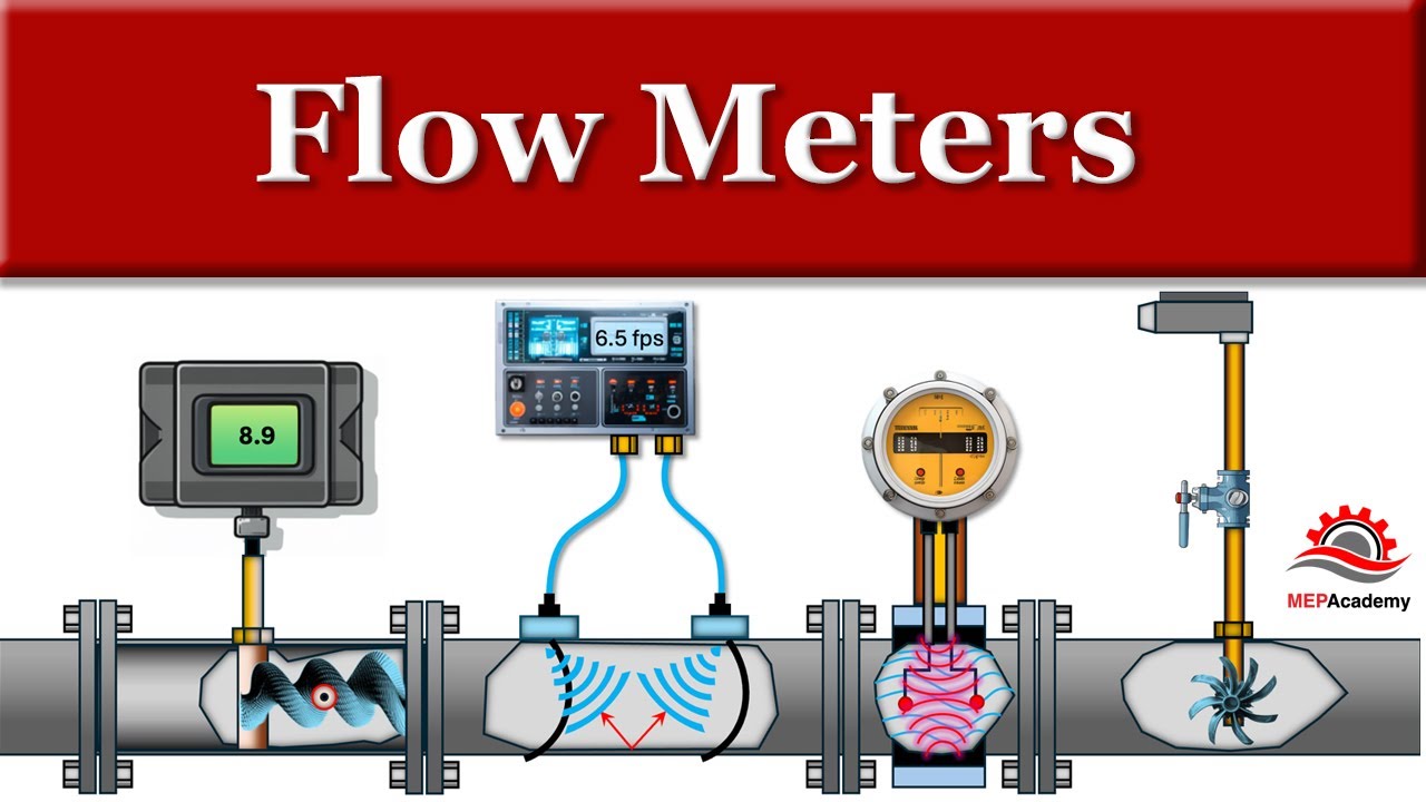
▶ Click to watch: How Electromagnetic Flow Meters Work — Full Explanation (YouTube)
Maintenance Requirements, Calibration Intervals, and Total Cost of Ownership
This section turns instrument specifications into financial decisions — which is the conversation that actually closes sales with MRO managers, procurement directors, and utility finance teams.
Electromagnetic flowmeters have no moving parts in contact with the process fluid. There are no turbine blades, no gears, no bearings to replace. In well-specified water and municipal applications, a properly installed magmeter runs reliably for 10 to 15+ years with an annual inspection that takes less than 30 minutes and generates no process downtime.
Contrast this with a mechanical turbine meter on the same line. Bearing replacement is typically required every 18–36 months in clean liquid service, and more frequently in any fluid with minor particulate content. Each replacement requires process isolation, draining the line, pulling the meter, replacing bearings or the rotor assembly, reinstalling and re-commissioning. A conservative estimate for three bearing replacements over 10 years — parts, labor, and 4–6 hours of process downtime per event — lands between $6,000 and $14,000 in operational cost on a mid-scale facility. That is before factoring in the calibration pulls that a mechanically wearing rotor requires every 12–24 months to catch K-factor drift.
A UK municipal water utility published a 10-year total cost of ownership comparison for 6-inch distribution line meters across their network, comparing installed mechanical turbine meters against electromagnetic replacements. The numbers are representative of what experienced engineers find consistently across similar applications.
| Categoria de custo | Mechanical Turbine Meter | Electromagnetic Magmeter |
|---|---|---|
| Purchase Price | $800 | $2,200 |
| Annual Maintenance — Parts + Labor | $320/year | $40/year |
| Calibration (every 2 years, 5 events) | $2,250 total | $1,400 total |
| Unplanned Downtime Events (10-year avg) | 3.2 events | 0.3 events |
| Estimated Downtime Cost (10 years) | $9,600 | $900 |
| 10-Year Total Cost of Ownership | $16,250 | $6,140 |
The magmeter costs 2.75× more at purchase. Over 10 years, it costs 62% less in total. This is the conversation that shifts a buyer from price-comparison mode to lifecycle-value mode — and it is the conversation your best customers are waiting to have.
Calibration intervals for electromagnetic flowmeters in general industrial service are typically 24 a 36 meses. Custody-transfer and billing applications require annual verification to satisfy regulatory or contractual obligations. Modern magmeters with HART or Modbus outputs support in-situ verification — checking measurement accuracy against internal reference diagnostics without removing the meter from the pipe. One European pharmaceutical facility extended calibration intervals from 12 to 36 months using in-situ Heartbeat Technology verification across 18 measurement points, saving approximately €12,000 per year in external calibration costs with full ISO 9001 documentation supporting the interval extension.
The comprehensive lifecycle analysis from Soaring Instrument on electromagnetic flow meter service life provides additional field data on typical failure modes, liner wear timelines, and the maintenance practices that sustain 15+ year service life across different industrial sectors.
Technology Comparison: Electromagnetic vs. Alternatives
The chart below compares electromagnetic flowmeters against four other common flow measurement technologies across five key performance dimensions, scored from 1 (weakest) to 5 (strongest) for typical industrial liquid applications.
TECHNOLOGY PERFORMANCE COMPARISON — INDUSTRIAL LIQUID METERING
(Score 1–5, higher = better performance in that dimension)

MEASUREMENT ACCURACY:
Electromagnetic (Mag)  ████████████████████ 5 — ±0.2% of reading
Coriolis Mass          ████████████████████ 5 — ±0.1% of reading
Vortex                 ████████████████     4 — ±0.5–1%
Turbine (clean liquid) ████████████████     4 — ±0.25–0.5%
DP / Orifice Plate     ████████████         3 — ±1–2%

ZERO-MAINTENANCE (no moving parts):
Electromagnetic (Mag)  ████████████████████ 5 — no moving parts
Coriolis Mass          ████████████████████ 5 — no moving parts
Vortex                 ████████████████     4 — no moving parts
DP / Orifice Plate     ████████████         3 — no moving parts (orifice erodes)
Turbine (clean liquid) ████                 1 — bearings, rotor wear

CHEMICAL / SLURRY TOLERANCE:
Electromagnetic (Mag)  ████████████████████ 5 — full-bore, wide liner choice
Coriolis Mass          ████████████████████ 5 — wide material options
Vortex                 ████████████         3 — clean fluids only
Turbine (clean liquid) ████                 1 — particulates destroy bearings
DP / Orifice Plate     ████████             2 — orifice edge erosion

INITIAL PURCHASE COST (higher score = lower cost):
Turbine (clean liquid) ████████████████████ 5 — $300–$1,200 (DN50)
DP / Orifice Plate     ████████████████     4 — $500–$1,500
Electromagnetic (Mag)  ████████████         3 — $800–$4,500
Vortex                 ████████████         3 — $800–$3,000
Coriolis Mass          ████                 1 — $3,500–$15,000+

10-YEAR TOTAL COST OF OWNERSHIP (higher score = lower TCO):
Electromagnetic (Mag)  ████████████████████ 5 — lowest TCO in most water/chemical apps
Coriolis Mass          ████████████████     4 — high CAPEX, near-zero maintenance
Vortex                 ████████████████     4 — competitive where applicable
DP / Orifice Plate     ████████             2 — frequent element replacement
Turbine (clean liquid) ████████             2 — bearing and calibration costs accumulate
Scores are generalized across typical industrial liquid applications. Results vary by specific process conditions, fluid properties, installation environment, and maintenance strategy.
Where Electromagnetic Flowmeters Are Deployed: Industry Distribution
The chart below shows the approximate distribution of magmeter installations across industrial sectors globally, based on 2025 market research data.
ELECTROMAGNETIC FLOWMETER APPLICATION DISTRIBUTION — 2025
(Percentage of global installed units by sector)

Water & Wastewater Treatment    ████████████████████████████████████ 35%
Chemical & Petrochemical        ████████████████████████████         27%
Food, Beverage & Pharma         ████████████████████                 17%
Mining & Minerals Processing    ████████████                         10%
Power Generation & Utilities    ████████                              7%
Other Industrial Sectors        ████                                  4%
Water and wastewater treatment remains the single largest sector, driven by aging infrastructure replacement programs, smart metering mandates, and tightening regulatory requirements on non-revenue water measurement. Many utilities in North America and Europe are replacing 20- to 30-year-old mechanical meters across their distribution networks on a systematic 10-year cycle — a sustained replacement demand that makes water utilities one of the strongest customer segments for distributors building a magmeter portfolio.
Chemical and petrochemical applications represent the fastest-growing segment, fueled by process automation upgrades, tightening environmental discharge monitoring requirements, and the shift toward continuous digital monitoring of aggressive and hazardous media that cannot be safely metered with moving-part instruments.
Sanitary and Hygienic Specifications: Food, Beverage, and Pharma
In food and beverage, dairy, and pharmaceutical manufacturing, the flowmeter is not just a measurement instrument — it is a component of the process boundary. Any surface in contact with product must meet hygienic design standards, support CIP/SIP cleaning cycles, and satisfy the regulatory requirements of the applicable food safety or pharmaceutical authority.
For these applications, the specification must address four additional dimensions beyond standard industrial requirements. Surface finish: the internal bore surface roughness must not exceed Ra 0.8 μm for food-grade applications and Ra 0.4 μm for pharmaceutical API production — rougher surfaces harbor biofilm in recesses that CIP chemicals cannot reach. Connection type: sanitary tri-clamp (ISO 2852) or DIN 11851 hygienic threaded fittings, not industrial flanges with bolt-circle bolt holes that create cleaning shadow zones. Liner and electrode: PFA liner with platinum or 316L SS electrodes, selected for both chemical compatibility with CIP agents (typically 1–3% caustic, 1–2% nitric or phosphoric acid) and product contact compliance. Enclosure rating: IP69K is mandatory for any location subject to direct CIP spray or steam sterilization.
In the US, 3-A Sanitary Standards certification indicates the meter meets the hygienic design requirements enforced by dairy and food processors. In Europe, EHEDG (European Hygienic Engineering and Design Group) certification serves the equivalent function. In pharmaceutical manufacturing regulated by the FDA or EMA, the full IQ/OQ/PQ (Installation, Operational, Performance Qualification) documentation package is required — including factory calibration traceability to NIST or equivalent national standard, dimensional inspection records, and material certificates for all wetted components.
Hazardous Area Specifications: ATEX, IECEx, and Class I Division
Applications involving flammable vapors, combustible gases, or explosive dust require explosion-protected instrumentation. The certification scheme depends on the installation region and the specific zone classification of the installation point.
ATEX Directive (EU): Equipment groups are classified by zone — Zone 0, 1, or 2 for gas/vapor hazards; Zone 20, 21, or 22 for dust hazards. The meter’s ATEX marking must specify at minimum the equipment category (II 1G, II 2G, or II 3G for gas zones), the gas group (IIA, IIB, or IIC), and the temperature class (T1 through T6). Using an II 2G meter in a Zone 0 classified area is a regulatory violation regardless of the certification label.
IECEx (International): The harmonized international counterpart to ATEX, used on projects in Australia, Middle East, Africa, and South America. ATEX and IECEx certificates are not automatically interchangeable — verify with the manufacturer whether both certificates are issued for the specific product configuration, or whether one must be re-applied for.
Class I Division 1 / Division 2 (North America): UL (Underwriters Laboratories) or FM (Factory Mutual) approved for use in classified locations per NEC Article 500. Division 1 covers locations where hazardous concentrations of flammable vapors exist under normal operating conditions; Division 2 covers locations where such concentrations are present only under abnormal conditions. Always reference the site’s electrical area classification drawing before specifying.
Compliance Documentation and Certification Requirements
OEM skid builders and EPC contractors operating in regulated industries or export markets need more than a working instrument — they need a documentation package that satisfies the requirements of the applicable regulatory authority, the end-user’s quality management system, and the project’s inspection and testing plan.
Standard documentation that should be requested at the time of purchase: factory calibration certificate with traceability to national standards (NIST in the US, PTB in Germany, NPL in the UK, NIM in China), material test certificate for all wetted metallic and non-metallic components, dimensional inspection record confirming face-to-face dimension and flange drilling, pressure test certificate (hydrostatic or pneumatic), conformity declaration (CE, UKCA, or applicable regional equivalent), and for hazardous area products, the ATEX or IECEx certificate with the specific certificate number and issuing notified body.
For pharmaceutical projects subject to 21 CFR Part 11 or EU GMP Annex 11, the transmitter must generate tamper-evident electronic records with time-stamped operator authentication. Most modern smart transmitters with HART or Modbus connectivity support this function through integration with a plant’s document management or SCADA historian system.
Supplier Capabilities: What to Look For Beyond the Datasheet
A flowmeter specification that looks identical on paper can deliver dramatically different outcomes depending on the supplier’s manufacturing quality, documentation capability, and post-sales technical support. For OEM skid builders, EPC contractors, and distributors building long-term supply relationships, supplier evaluation is as important as product evaluation.
Key supplier capabilities to assess: ISO 9001 certified manufacturing with documented calibration traceability, the ability to supply custom bore sizes and face-to-face dimensions for non-standard applications, OEM labeling and private-brand manufacturing capability for distributors and OEM builders, batch-lot material traceability for pharmaceutical and food-grade projects, technical application support that can answer liner-electrode selection questions for specific fluid chemistries, and a clear policy of manufacturer-direct pricing to distributors without undercutting distribution channels through direct end-user sales.
Instrumentos Jade Ant manufactures electromagnetic flowmeters from DN10 to DN2000 in full-bore and insertion configurations, covering all six standard lining materials and five electrode materials. ISO 9001 certified, with ATEX, CE, and SIL documentation available for hazardous area, European market, and safety-instrumented system requirements. Factory calibration certificates traceable to national standards are standard with every shipment. The engineering team provides free technical consultation on liner-electrode selection for specific fluid chemistries, custom bore sizing for non-standard applications, and OEM documentation packages for new-product qualification programs. Rush quotations within 12 hours are available for time-sensitive projects.
For distributors building a magmeter portfolio, the top 10 magnetic flowmeter applications guide provides a sector-by-sector account development roadmap — identifying where magmeter demand is strongest, which specifications recur most frequently in each sector, and what competitive positioning arguments win against lower-price alternatives.

Retrofit Opportunities: Replacing Mechanical Meters With Magmeters
Many distributors and MRO teams are sitting on a replacement opportunity their customers don’t know they have. Aging turbine meters, oval gear meters, and paddlewheel meters can often be replaced with magmeters using existing pipe flanges and cable trays — no major re-piping or control system redesign required.
Retrofit makes commercial sense when: the existing mechanical meter requires annual bearing replacement costing $300–$800 in parts and labor per event; measurement accuracy is declining despite recalibration because rotor wear has shifted the K-factor beyond correction range; the customer has added VFDs or other EMI-generating equipment near the meter since installation, causing unexplained reading fluctuations; or the customer is planning a SCADA integration upgrade and needs a smart digital output the existing meter cannot provide.
Before proposing a retrofit, four checks must be completed. Confirm fluid conductivity exceeds 5 μS/cm. Identify pipe material and determine whether grounding rings are required. Confirm flange drilling pattern (ANSI 150/300 or DIN PN10/16/25/40) and face-to-face dimension match, or specify a replacement with adapter flanges. Confirm minimum 5D upstream and 2–3D downstream straight run is available from the existing installation location — if not, evaluate whether the meter can be relocated 300–500 mm along the pipe.
For technology-level comparison of when magnetic, turbine, or ultrasonic meters represent the strongest replacement choice in a given application, the ultrasonic vs. magnetic vs. turbine flow meter decision guide covers the cross-technology selection logic with application-specific case examples. And for distributors wanting a broader view of where the common selection mistakes happen — and how to avoid them before they become warranty claims — the flow meter selection mistakes case study library documents real field failures with root-cause analysis and corrective specifications.

Quick-Reference Specification Checklist
Use this checklist before finalizing any electromagnetic flowmeter specification. Every unchecked box is a potential field failure waiting to happen.
Application Fundamentals
- Continuous or batch process defined?
- Control loop or monitoring/totalization role confirmed?
- Duty cycle documented?
Fluid Properties
- Fluid conductivity confirmed ≥ 5 μS/cm? (Test with handheld meter if unsure)
- Full fluid chemistry specified — including trace components and concentration ranges?
- Liner material chemically compatible with all process fluids in the rotation?
- Electrode material matched to fluid corrosivity?
- Abrasion level defined: clean, slurry, or heavily abrasive?
- Gas or vapor phase possible in the line at the meter location?
Process Conditions
- Maximum operating pressure within meter pressure rating (including surge/hammer margin)?
- Temperature range — operating, maximum, minimum — within lining and transmitter specifications?
- Flow velocity at normal operating conditions in the range 0.3–10 m/s (0.3–3 m/s for abrasive service)?
- Minimum detectable flow rate within the meter’s specification?
Installation Requirements
- Pipe always full at installation location? (Confirm with process engineer)
- Minimum 5D upstream / 2–3D downstream straight run available?
- Electrode position: 3 o’clock and 9 o’clock for horizontal installation?
- Grounding method confirmed for pipe material type?
- IP rating appropriate for washdown, submersion, or CIP exposure?
- Hazardous area zone classification verified? ATEX/IECEx/Division certification required?
Output and Communication
- Output format compatible with site PLC/DCS input card?
- Communication protocol aligned with site standard (HART/Modbus/Profibus)?
- Local display required? Remote-mount transmitter needed for high-temperature or vibration location?
- Pulse output needed for batch totalizer or billing system?
Commercial and Documentation
- Certifications required: CE, ATEX, IECEx, 3-A, EHEDG, PED, SIL — specify all?
- Factory calibration certificate with national standards traceability required?
- Material certificates for wetted components required?
- OEM labeling or private branding required?
- IQ/OQ/PQ documentation package required (pharma/food applications)?
Perguntas frequentes
What is the minimum fluid conductivity for an electromagnetic flowmeter to work accurately?
The minimum is 5 μS/cm for standard meters. Some specialized high-sensitivity units measure down to 0.5 μS/cm for applications like demineralized water. Always verify the specific meter model’s minimum conductivity specification — it varies between manufacturers and configurations. If the fluid conductivity is unknown, measure it on-site with a handheld conductivity meter before finalizing the specification.
Can electromagnetic flowmeters measure petroleum, diesel, or hydrocarbon solvents?
No. Electromagnetic flowmeters fundamentally cannot measure non-conductive fluids. Hydrocarbons, petroleum products, and most organic solvents have conductivity values near zero. The operating principle requires an electrically conductive medium — without it, no signal is generated regardless of meter brand, calibration, or firmware version. For these fluids, the correct technology is a Coriolis mass flowmeter, a turbine meter, or an oval-gear positive displacement meter depending on the required accuracy and flow range.
Do I need to match the flowmeter bore to the pipe size?
No — and this is one of the most important points in this guide. The meter bore should be selected to achieve a flow velocity of 1.5–3 m/s at normal operating flow, not to match the nominal pipe diameter. For large pipes carrying low flow rates, a reduced-bore magmeter with upstream and downstream concentric reducers is frequently the correct and more cost-effective specification. It performs better within its accuracy specification and costs significantly less than the full-bore equivalent.
What lining material should I specify for abrasive mining slurry applications?
Polyurethane is the best starting point for abrasive, non-corrosive slurries — ores, sand, tailings, raw aggregate — at temperatures below 70°C. For corrosive-and-abrasive combinations such as acid mine drainage or mineral acid leach slurries, ceramic (Al₂O₃) lining offers the best combination of abrasion and corrosion resistance. In both cases, keep flow velocity below 3 m/s to maximize liner service life.
Are electromagnetic flowmeters suitable for CIP/SIP-cleaned food and pharmaceutical processes?
Yes, when correctly specified. The required configuration is: PFA or PTFE lining, platinum or 316L SS electrodes, tri-clamp or DIN 11851 hygienic end connections, IP69K housing for CIP spray and steam cleaning resistance, and internal bore surface roughness Ra ≤ 0.8 μm. In the US, look for 3-A Sanitary Standards certification. In Europe, EHEDG approval. For pharmaceutical processes, GMP-compliant calibration documentation and IQ/OQ/PQ support are required.
Is vertical pipe installation acceptable for electromagnetic flowmeters?
Yes — vertical upward flow is often the preferred installation in slurry and solid-laden fluid applications. Upward flow keeps the pipe full and prevents solids from settling on the electrodes. Vertical downward flow is acceptable only when the pipe is confirmed continuously full. For horizontal installations, the electrodes must be at the 3 o’clock and 9 o’clock positions — not 12 o’clock (gas accumulates above the upper electrode) and not 6 o’clock (solids settle on the lower electrode).
How much straight pipe run is needed upstream and downstream of the meter?
The industry-standard minimum is 5 pipe diameters (5D) of unobstructed straight pipe upstream e 2–3D downstream. After elbows, partially open valves, pumps, or reducers, allow 10D or more upstream. Some specialized meter designs are validated for reduced straight-run installations — always verify with the specific manufacturer’s installation data sheet.
How often should electromagnetic flowmeters be calibrated?
For general industrial monitoring: every 24–36 months. For custody-transfer or regulatory compliance metering: annually. For low-criticality monitoring with modern in-situ diagnostic capability: calibration intervals can be extended to 5+ years under a risk-based ISO 9001 maintenance program, supported by traceable in-situ verification records. Turbine meters — for comparison — typically require calibration every 12–24 months because rotor bearing wear progressively shifts the K-factor between events.
What is the difference between flanged, wafer, and insertion-type magmeters?
Flanged meters bolt directly between pipeline flanges and are the standard for industrial applications up to DN2000, providing full-bore accuracy and the highest mechanical integrity. Wafer-style meters clamp between flanges using long bolts passing around the meter body — lighter, more compact, and lower cost than flanged for smaller bore sizes (DN15–DN300), suited for lower-pressure systems. Insertion-type meters insert a probe sensor through a tapping in a large-diameter pipe — used on DN300+ lines where full-bore meters become impractical or cost-prohibitive, accepting lower accuracy (±1–2%) in exchange for dramatically lower installation cost.
Can I specify HART output on an electromagnetic flowmeter even if the current SCADA doesn’t use it?
Yes — and it is usually worth doing. HART capability adds very little to the purchase cost and gives the end-user the future option to add smart device management, remote diagnostics, and transmitter configuration via HART handheld or HART-enabled asset management software without changing the field instrument or the existing 4–20 mA wiring. It is an inexpensive specification upgrade that protects the customer’s future flexibility and reduces the risk of a meter swap when the SCADA system is eventually modernized.
How do I troubleshoot a magmeter that shows zero or erratic readings?
Work through four checks in sequence. First: confirm the pipe is full — partial pipe is the most common cause of zero output. Second: check fluid conductivity — if process fluid has changed or been diluted below 5 μS/cm, no signal will be generated. Third: check ground resistance — a resistance above 10 Ω at the grounding ring indicates a grounding fault, which is the root cause of approximately 50% of magmeter field failures. Fourth: identify new EMI sources — check whether VFDs, welding equipment, or large motors have been installed near the meter since commissioning and whether the signal cable shielding is continuous and intact.
What certifications should I require for a magmeter going into a European hazardous area installation?
For European Zone 1 gas hazard locations, require at minimum: ATEX II 2G certification with the appropriate gas group (IIA, IIB, or IIC) and temperature class (T1–T6) for the process fluid involved, plus a CE Declaration of Conformity under the ATEX Directive 2014/34/EU. For global projects, also request the IECEx certificate — the international equivalent, which satisfies local authority requirements in Australia, Middle East, Africa, and many Asian markets. Always verify the exact zone classification against the site’s area classification drawing, not a general project description.
What support does Jade Ant Instruments provide for OEM skid-building projects?
Jade Ant Instruments supports OEM customers from specification through delivery with: custom bore and flange specification for non-standard applications, OEM private-label and custom-branding options, factory calibration certificates traceable to Chinese national standards (equivalent to NIST traceable on request), material test certificates for all wetted components, full ATEX and CE documentation for European-market skids, dimensional drawings in DXF/DWG format, and engineering consultation on liner-electrode selection for specific fluid chemistries. Rush quotations are available within 12 hours for standard configurations. Contact the team via the Jade Ant Instruments project enquiry page to discuss your project requirements.
Can electromagnetic flowmeters measure bidirectional flow?
Yes — this is one of the functional advantages of electromagnetic flowmeters over several competing technologies. Standard magmeters detect both forward and reverse flow automatically based on the polarity of the induced signal. The transmitter displays flow direction and rate simultaneously and can output separate signals for each direction. This makes magmeters well-suited for pump recirculation systems, distribution network balancing, tidal flow applications, and tank filling-and-draining cycles where flow reversal is part of normal operation.
What is the typical service life of an electromagnetic flowmeter in municipal water service?
In correctly specified and properly installed applications in clean municipal water, 15 to 20 years of reliable service is realistic. The most common causes of premature retirement are: wrong liner material selected (hard rubber specified on a slightly acidic or high-temperature line), grounding neglect allowing long-term low-level EMI damage to the transmitter, and physical housing damage from UV exposure or mechanical impact over time. Annual grounding verification, a 3-yearly impedance check on the electrodes, and keeping the transmitter housing seals intact are sufficient to sustain maximum service life with minimal intervention.
Ready to Specify the Right Meter for Your Next Project?
Getting the specification right from the start is the difference between a satisfied long-term customer and a costly warranty call six months after commissioning.
Instrumentos Jade Ant manufactures electromagnetic flowmeters from DN10 to DN2000, across all standard lining and electrode configurations, with ISO 9001 certification, ATEX and CE documentation, and direct technical support for OEM, EPC, and distributor customers worldwide. Same-day quotation on standard configurations. Free technical consultation on application-specific liner-electrode selection.
For distributors evaluating how electromagnetic flowmeters fit into a broader portfolio strategy, the leading flow meter manufacturers comparison guide maps supplier capabilities, product breadth, and market positioning across the major brands — a practical resource for building a competitive product mix without overlap or gaps.
The right flowmeter doesn’t just measure flow. It protects your client’s process, your technical reputation, and your margin.
Last updated: August 2026. Data references include Mordor Intelligence Electromagnetic Flowmeter Market Report 2025–2026, Fortune Business Insights Flow Meter Market Report 2025, Knowledge Sourcing Intelligence Electromagnetic Flow Meter Market Forecast 2026–2031, Soaring Instrument field analyses, and published industry installation standards (ISO, API, IEC, AGA).