Ultra Flow Meter Maintenance: A Practical Roadmap for Calibration, Drift Control and Field Troubleshooting

Image: Josefus2003, public domain, via Wikimedia Commons
Quick answer: An Ultra Flow Meter stays accurate when you record a clean baseline at commissioning, control grounding and shielding, and track a few diagnostic numbers over time. Most failures come from the installation around the meter. The meter itself is rarely the cause.
A note on the numbers in this guide: Field figures come from Jade Ant Instruments’ service records on electromagnetic (no-moving-parts) meters. Those meters behave like the Ultra Flow Meter in the ways that matter for maintenance. If your Ultra Flow Meter manual gives a different limit, follow the manual.
I. Introduction
A flow meter sits in the middle of money. It decides how much chemical goes into a reactor, what a customer pays for water, and whether a discharge report passes an audit. When its reading is off by 1%, every one of those numbers is off by 1%.
Here is what that costs on a real line. Take a water billing meter running 800 GPM around the clock with a +1% bias:
At a typical rate of 3.50 USD per 1,000 gallons, that is about 14,700 USD of unmetered water every year, from one meter.
The pain points we hear most
If you build skids, commission plants, keep them running, or supply the meters, these three problems will sound familiar:
- Unexpected downtime. ABB’s downtime research found that 83% of industrial decision-makers say an hour of unplanned downtime costs at least 10,000 USD. A meter fault that stops a dosing line gets expensive quickly.
- Calibration drift. The meter still shows a number. It just slowly stops being the right one.
- Field failures. A site visit for a 40 USD cable fault can cost thousands once travel and lost production are counted.
What this guide gives you
This is a maintenance roadmap for integrators and MRO teams. It follows the life of a meter in order: baseline, drift control, troubleshooting, hardware care, communications, scheduling, outdoor service, and handover. Instrumentos Jade Ant builds its meters for OEM and utility projects, and the field notes below come from that work.
Plain-English term: signal drift. A slow, steady change in a meter’s reading when the real flow has not changed. Think of a bathroom scale that adds 200 grams every few months.
II. Establishing a Professional Calibration Baseline
Precision begins at commissioning. If you never record how the meter behaved on day one, you cannot tell on day 500 whether it has changed.
Zero-point verification: remove offset errors first
Zero point is what the meter reads when nothing is flowing. It is the easiest test in this guide and the one most often skipped.
- Close both block valves so the pipe is full but still.
- Confirm zero flow. Pressure should hold steady with no decay.
- Read the meter. A good result is 0.00 ± 0.05% of full scale.
- Check the 4–20 mA output. It should sit at 4.000 ± 0.005 mA.
On a 600 GPM meter, the tolerance works out to a small number:
If the zero is outside that band, adjust it with the transmitter’s auto-zero function and write down both the “as-found” and “as-left” values. Jade Ant’s magnetic flow meter calibration tips walk through the full eight-step onsite sequence.
Industry insight: The zero check takes about ten minutes, yet it catches grounding faults, coated electrodes, and bad wiring in one test. A non-zero reading at confirmed zero flow is the simplest early warning you have.
Document the installation geometry
Straight run is the length of straight pipe before and after the meter that lets the flow settle. Elbows, valves, and pumps make the flow swirl, and swirl biases the reading.
At commissioning, photograph the meter in place and record these items on the commissioning sheet:
- Upstream and downstream straight run, in pipe diameters (about 5D upstream and 2–3D downstream is typical for this meter class)
- What sits upstream: elbow, partly open valve, reducer, or pump
- Electrode orientation (3 and 9 o’clock on horizontal pipe)
- Gasket bore versus pipe bore (within 0.5 mm)
- Flange alignment (concentric within 1.5 mm, about 1/16 inch)
This matters because installation errors dominate accuracy complaints. Jade Ant reviewed 1,847 field tickets from 2023 to 2025:
Source: Jade Ant Instruments field-service database, 2023–2025.
The three biggest bars (straight run, orientation, and grounding) add up to 61% and are all fixed at installation. Jade Ant’s Guia de práticas recomendadas para instalação de medidores de vazão covers each of them in detail.
Set a site-specific calibration schedule
Calibração adjusts a meter to match a trusted reference. Verification only checks whether it is still within tolerance. Do not use one word for both.
Start from the fluid and the stakes. Fouling-prone and billing-grade lines get checked more often.
| Service | In-situ verification | Bench (lab) calibration |
|---|---|---|
| Water billing | Every 12 months | Every 3–5 years |
| Wastewater | Every 6 months | Every 2–3 years |
| Chemical processing | Every 6–12 months | Every 1–2 years |
| Pharma / food | Every 3–6 months | Every 12 months |
| HVAC / chilled water | Every 24 months | Every 5 years |
Source: Jade Ant Instruments troubleshooting guide. Shorten any interval if your last as-found error was above 0.3%.

Image: Cjp24, public domain, via Wikimedia Commons
Whatever interval you choose, use a reference at least four times more accurate than the meter. For a 0.5% meter:
For traceability, NIST’s guidance on metrological traceability explains why a certificate needs an unbroken chain back to a national standard.
III. Advanced Strategies to Prevent Signal Drift
Drift has electrical causes and environmental causes. The first step is knowing which one you are fighting.
Shielding and grounding to defeat EMI in skid environments
EMI (electromagnetic interference) is electrical noise from motor drives, welders, and power cables. The meter’s electrode signal is only millivolts, so noise shows up directly as a flow reading.
Soaring Instrument’s field analysis found that about half of mag meter accuracy complaints trace back to grounding. Jade Ant’s own records agree: grounding faults caused 32% of failed calibrations.
A practical grounding and shielding routine for skids:
- Measure resistance from the process fluid to the plant earth bus. It should read under 10 Ω.
- On plastic, FRP, or lined pipe, install grounding rings on both flanges and bond them to earth. Chase Filter’s grounding ring explainer has clear photos for installer training.
- Use shielded twisted-pair cable and ground the shield at the transmitter end only.
- Keep signal cables 300 mm away from power cables above 120 VAC. Where they must cross, cross at 90 degrees.
- If noise persists, add a ferrite choke within 150 mm of the junction box.
Industry insight: On a new skid, the most common startup callback is a missing grounding ring on a plastic spool. Put the ring on the bill of materials for every non-metallic or lined line, so it cannot be forgotten on the shop floor.
Watch temperature swings and apply compensation
Temperature cycling slowly moves transmitter electronics. Jade Ant’s records show zero-offset creep of roughly 0.1–0.5% per year. Three habits keep it in check:
- Turn on any automatic temperature compensation your transmitter offers, and confirm the setting after every firmware or parameter change.
- Log ambient temperature inside outdoor enclosures. A sun-baked cabinet ages electronics faster.
- Repeat the zero check after big seasonal swings, not only on the calendar date.
Turbines, Inc. explains why all flow meters drift, and that drift is normal. What matters is how quickly you catch it.
Verify with a master meter or weigh scale on high-accuracy lines
For custody, billing, or dosing lines, compare against something better than the meter itself. Two common options:
- Master meter: a calibrated reference meter in series, ideally 4:1 more accurate.
- Weigh scale (gravimetric) test: divert flow into a tank on a scale and compare mass and time.
Portable clamp-on meters are handy but typically accurate to 1–3%, so use them for gross-error checks, not precision work. Jade Ant’s flow meter sensor calibration setup guide compares methods, tools, and intervals.
IV. Systematic Troubleshooting of Common Field Issues
MTTR (mean time to repair) is the average time from “something is wrong” to “it is fixed”:
For example, 5 repairs taking 30 hours in total gives an MTTR of 6 hours. A fixed diagnostic order often halves that, because you stop replacing parts that were never broken.
Noise versus signal in erratic readings
Before touching the meter, ask whether the flow itself is steady. Check the pump curve, valve position, and tank level. If a 5% wobble follows pump speed, it is a process effect, not a meter fault.
If the process is steady, the culprit is usually one of these:
| Symptom | Most likely causes, in order | First check |
|---|---|---|
| Fluctuating reading, steady flow | Air in pipe, grounding fault, drive noise, electrode coating | Confirm the pipe is full |
| Reads consistently high | Zero-offset drift, ground loop, wrong setting | Zero-flow check |
| Reads consistently low | Electrode fouling, partly full pipe, low conductivity | Electrode impedance |
| Zero with confirmed flow | Empty-pipe alarm, electrode short, power fault | Power and alarm log |
| Unstable only during production | Drive switching, welding nearby, big motor starts | Cable routing |
Source: Jade Ant Instruments troubleshooting guide.
Here is how often each root cause showed up in meters that failed their first calibration check:
Source: Jade Ant Instruments field-service and calibration database, 2023–2025.
Grounding and fouling together account for 58%. That is why the first two checks below target them.
Physical obstructions and coating build-up
Electrode fouling is a film of scale, grease, biofilm, or sludge that insulates the sensing contact from the fluid. The reading drifts low over weeks, often by 2–8%.
The transmitter usually tells you before the numbers do. Look for these electrode impedance values:
- Healthy: roughly 1–50 kΩ
- Coating: above 100 kΩ
- Short circuit: below 0.5 kΩ, which means a conductive deposit or damaged liner
An example: a dilute-acid dosing meter reads fine for two years, then starts reading 3–4% low after a raw-material supplier change upstream. You can often diagnose it from the control room. The impedance trend climbs, the zero at no flow is no longer zero, and the cause is a coating from the new chemistry.
Use onboard diagnostics to separate hardware failure from installation error
Open the transmitter’s diagnostic menu before opening any junction box. Here is how to read it:
| Alert | What it usually means | Action |
|---|---|---|
| Empty pipe detected | Air ingress or line drain-back | Check pipe fill and vents |
| Electrode impedance high | Active fouling | Schedule cleaning |
| Electrode impedance low | Deposit bridging electrodes | Inspect immediately |
| Coil current off by more than 5% | Coil or wiring resistance problem | Test coil and wiring |
| High noise level | EMI or two-phase flow | Check routing and air |
| Zero alarm | Zero drifted past limit | Re-zero at confirmed zero flow |
Source: Jade Ant Instruments troubleshooting guide.
A simple rule helps here. If diagnostics show a clean electrode, normal coil current, and low noise but readings are still wrong, the cause is almost always outside the meter: pipe fill, grounding, or the PLC scaling.
Jade Ant’s magnetic flow meter troubleshooting guide has a longer symptom-to-cause table. For a visual walk-through, this video covers the five most common faults:
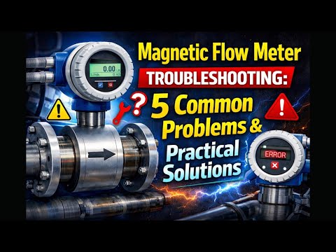
Video: “Magnetic Flow Meter Troubleshooting: 5 Common Problems & Practical Solutions.” Click the image to watch on YouTube.
V. Optimizing Hardware Integrity for Long-Term Reliability
Electronics only stay accurate when the metal, rubber, and bolts around them stay sound.
Inspect seals, gaskets, and connection points
Leaks hide in small places. A weeping cable gland can put moisture on the terminals, and moisture turns into a signal fault months later.
On every planned visit, check:
- Rust or blistered paint around flanges and bolts
- Water marks under cable glands and conduit entries
- Cracked display windows and loose junction boxes
- Gasket condition: never reuse a compressed gasket, and make sure its bore does not protrude into the flow
- Flange bolts, tightened in a star pattern in three passes (30%, 60%, then 100% of final torque)
Industry insight: A gasket change can shift the bore alignment by a fraction of a millimeter. Treat any gasket replacement as a trigger for a zero check afterward.
Manage vibration in high-pressure systems
Pump vibration loosens terminals, fatigues cables, and passes stress into the sensor body. Pipe stress can also distort flanges and eventually affect liner or electrode sealing.
Practical fixes, in order of cost:
- Support the pipe on both sides of the meter so the meter body carries no weight.
- Keep the meter at least five diameters from pumps and compressors when layout allows.
- Use flexible connectors or isolation mounts near reciprocating equipment.
- Use vibration-rated terminals and strain relief on remote cables.
Audit materials against the real fluid
O liner is the protective coating inside the tube, and the electrodes are the sensing contacts. Wrong choices cause a large share of chemical-service failures.
| Material | Typical role | Good for |
|---|---|---|
| Hard rubber | Liner | Water, wastewater, mild slurry |
| PTFE | Liner | Strong acids and alkalis |
| PFA | Liner | Pharma, food, high-purity water |
| Polyurethane | Liner | Abrasive mining slurry |
| Ceramic | Liner | Severe abrasion plus corrosion |
| Aço inoxidável 316L | Electrode | Water and mild chemicals |
| Hastelloy C | Electrode | Acid service and CIP cleaning |
| Titânio | Electrode | Seawater and chlorinated fluids |
Source: Jade Ant Instruments selection guides.
A telling sign of chemical attack is blistering: raised bubbles on the liner where fluid has soaked in and trapped vapor. If you see it, the liner material was wrong for that fluid. Audit materials after any process change, such as a new cleaning chemical, a pH adjustment, or a new supplier. Jade Ant’s liner and electrode selection guide maps materials to common fluids.
VI. Integration and Communication Stability
A perfect measurement is worthless if it arrives garbled. Check the path from the meter to the controller as carefully as the meter.
Verify the 4–20 mA loop and digital protocols
4–20 mA is a current signal where 4 mA means zero flow and 20 mA means full scale. HART (Highway Addressable Remote Transducer) puts digital data on the same two wires. Modbus is a common digital protocol that carries readings and diagnostics to a PLC or SCADA system.
A quick loop test takes about five minutes:
- Simulate 4.00 mA and 20.00 mA from the transmitter.
- Confirm the PLC shows zero and full-scale engineering units.
- Check scaling, channel status, and units. A working meter is often blamed for a wrong PLC scale.
- For HART, confirm loop resistance (about 250–1,100 Ω) and avoid T-junctions in the cable run.

Image: ASDFS, CC BY-SA 4.0, via Wikimedia Commons
For background on how HART works, see the HART protocol overview. For a broader comparison of 4–20 mA, HART, and Modbus, Turbines, Inc. has a clear protocol explainer.
Update firmware, then re-verify
Firmware can fix known bugs and improve how the meter processes its signal. But treat it as a maintenance event, not a free upgrade.
- Save a configuration backup before the update.
- Record the old and new firmware versions.
- Run a zero check and a multi-point verification afterward. Jade Ant lists firmware updates among the events that call for recalibration.
Tune damping to stop “hunting”
Damping smooths a noisy reading by averaging it over a time constant (τ). Hunting is when a control loop keeps overshooting because the signal is jumpy.
Time to settle after a step change is roughly:
With τ = 10 seconds, the reading takes about 30 seconds to settle. That is fine for a tank filling line, but too slow for a fast dosing loop. Raise damping a little at a time, and stop when the noise is gone. Too much damping hides real changes.
O datasheet reading guide from Jade Ant explains response time and output settings so you can match them to your loop.
VII. Preventive Maintenance (PM) Scheduling for MRO Teams
Corrective maintenance fixes what broke. Predictive maintenance fixes what is about to break. The second costs less over the life of the plant.
A tiered checklist: daily, monthly, annually
| Frequency | Tarefa | Time |
|---|---|---|
| Daily (control room) | Scan flow trends for flat lines, spikes, or new noise; check alarm log | 2 min per meter group |
| Monthly | Review electrode impedance and noise trends; check cable glands for moisture; confirm display and totalizer | 10 min per meter |
| Every 6 months | Zero-flow check; ground resistance below 10 Ω; terminal tightness | 30 min |
| Annually | In-situ verification against a reference; flange and gasket inspection; save configuration backup; update calibration records | 2–4 h |
| Every 3–5 years | Bench calibration, or sooner if as-found error exceeds 0.5% | 1–2 days plus lab time |
Jade Ant’s magnetic water flow meter maintenance guide adds cleaning methods by deposit type and a LOTO (lockout/tagout) sequence before any work on the pipe.
Cost matters when you choose a method. Here is what each type of check costs for a typical 4-inch meter:
Source: Jade Ant Instruments calibration guide.
The cheapest check is also the quickest, so use it often and save the lab for when the in-situ test fails.
Condition-based monitoring: act when performance dips
Condition monitoring means tracking a measurable parameter and acting when it changes meaningfully. For flow meters, you track a few diagnostic numbers instead of following the calendar.
Three triggers that justify a visit:
- Electrode impedance rises more than 50% above the commissioning baseline.
- Zero reading at no-flow moves outside 0.05% of full scale.
- Totalizer volume disagrees with an upstream meter or tank inventory by more than 1% over 24 hours.
Say you log impedance daily in your historian. A meter climbing from 50 kΩ to 80 kΩ in six months is heading for trouble. You clean it at the next planned outage, before it reaches 100 kΩ and starts under-reading. Jade Ant estimates that in a plant with 40–100 meters, this shift from emergency to planned work can save 30,000–80,000 USD per year in emergency service and downtime.
Spare-parts inventory for wear items
Keep the parts that fail in the field, not the ones that rarely fail:
| Spare | Why it is on the list |
|---|---|
| Grounding rings, correct size | Cheap, and a missing one stops the job |
| Signal cable, pre-terminated | Cable damage is a top-four cause of drift |
| Gasket and bolt sets | Never reuse compressed gaskets |
| Cable glands and seals | Prevent moisture faults |
| One spare transmitter per site or fleet | Swaps a day-long fault into an hour |
| Configuration backup file | Makes any swap quick |
For meters that have moving parts, the list is longer. Rotor bearings, for example, wear out and need replacing every few years. That wear is one reason a turbine-style design costs more to maintain:

Image: Ruben Castelnuovo, CC BY-SA 3.0, via Wikimedia Commons
Jade Ant’s Coriolis flow meter maintenance checklist is a good template if your plant runs mixed meter types and you want one CMMS format.
Keep a maintenance log you can sort
Copy this into a spreadsheet. The columns let you spot trends instead of just recording events.
| Date | Meter tag | Service | Zero reading | Impedance (kΩ) | Action | Next due |
|---|---|---|---|---|---|---|
| 2026-05-03 | FIT-204 | Filtered water | 0.01% FS | 48 | Zero check, terminal inspection | 2026-11-03 |
| 2026-05-03 | FIT-311 | Wastewater return | 0.09% FS | 96 | Cleaned electrodes, flushed line | 2026-08-03 |
| 2026-06-10 | FIT-118 | Chemical dosing | 0.02% FS | 62 | Re-torqued flange, checked ground | 2026-12-10 |
VIII. Environmental Adaptation for Utility and Municipal Systems
Outdoor and underground meters face rain, heat, lightning, and floods. They are also the hardest to reach, so a failure costs more.
Protect electronics with the right enclosure rating
An IP rating tells you how well an enclosure keeps out dust and water. The IP code uses two digits: the first for dust, the second for water. In the US, NEMA types serve a similar purpose, though the two systems are not exactly equal.
| Location | Suggested minimum | Why |
|---|---|---|
| Indoor, dry plant room | IP65 | Washdown splashes |
| Outdoor, exposed | IP66 or NEMA 4X | Rain jets, UV, corrosion |
| Underground vault that can flood | IP68 | Continuous immersion |
Jade Ant’s electromagnetic meters are available at IP65 as standard and IP68 for submersible use, as listed on the Intelligent Electromagnetic Flow Meter specification page. Whatever the rating, keep cable glands tight, face cable entries downward, and add a drip loop.
Manage surge on long cable runs
Long cables act like antennas for lightning and switching surges. Industry practice for municipal sites:
- Fit surge protectors on both power and signal lines.
- Bond the protector to a low-resistance earth, since a surge device with a poor ground does very little.
- Keep the earth path short and straight.
- Check protector status lights on every six-month visit.
Hold accuracy through changes in fluid and air content
For magnetic-type meters, viscosity does not change the reading, but other things do. Pay attention to:
- Conductivity. Keep it above about 5 µS/cm. Municipal drinking water typically sits at 50–500 µS/cm, which is comfortable.
- Air. Bubbles give unstable, usually low readings. Mount the meter on a vertical upward run or a low point that stays full, and keep it away from pump suctions and high-point vents.
- Solids and chemistry. Coagulants, lime, or polymer changes upstream can start new coating. Add a verification after any dosing change.
Utility teams comparing options can use Jade Ant’s water flow meter selection tips e o magnetic versus ultrasonic comparison for wastewater to match technology to site conditions.
IX. Quality Assurance for OEM and System Integrators
You can only promise “as-delivered performance” if you can prove it later. These three habits make that proof easy.
Build a complete handover package
A good package means the customer’s team never has to call you for basic facts. Include:
- Factory calibration certificate with traceability statement
- As-found and as-left commissioning data, including zero check and a 5-point verification (0%, 25%, 50%, 75%, 100% of span)
- Photos of the as-installed meter, grounding, and cable routing
- Configuration backup file and parameter list
- Maintenance manual and the PM checklist from Section VII
- Spare parts list with part numbers
O Endress+Hauser calibration management white paper is a useful outside reference for what auditors expect to see.
Add remote monitoring for proactive support
Remote diagnostics turn “the line is down, come now” into “we saw the impedance rising, here is the fix.” Jade Ant offers remote diagnostic support through HART pass-through, so engineers can read transmitter diagnostics without a site visit.
For sites with no wiring to a control room, wireless meters report on their own. Smart ultrasonic flow meters with wireless and touchscreen features are one option when running cable is not practical.
Close the loop between field failures and design
Every field failure is a design note. Keep a simple feedback loop:
- Log each failure with its root cause using the same six categories as the pie chart in Section IV.
- Review the log each quarter with the design team.
- Turn repeating causes into design rules. For example, “grounding ring on every non-metallic spool” or “signal cables on a dedicated tray.”
Industry insight: An OEM that tracks root causes will usually find two or three repeat offenders. Fixing those in the next skid revision can cut warranty callbacks faster than any inspection program.
X. Conclusion
Routine checks, structured troubleshooting, and systemic reliability work together. The baseline tells you what normal looks like, the diagnostics tell you when it changes, and the PM schedule tells you who acts and when.
What good maintenance is worth
The numbers are clear. A +1% bias on an 800 GPM line is about 14,700 USD a year. A 10-minute zero check can catch it. A grounding ring costs a small fraction of a service call. Moving from emergency to planned work saves tens of thousands of dollars in a mid-size plant.
Standardize across your installed base
Do not leave these protocols to individual technicians. Put them on paper:
- One commissioning sheet with zero check, geometry, and 5-point verification
- One PM checklist, loaded into your CMMS
- One spare kit per site
- One root-cause log, reviewed every quarter
If you want help applying this to your own fleet, the Jade Ant Instruments contact page is the fastest way to reach the technical team. You can also browse more field guides on the Jade Ant flow meter blog.
Glossário de termos-chave
4–20 mA loop: A current signal where 4 mA equals zero flow and 20 mA equals full scale. Example: 12 mA means 50% of span.
Calibration vs. verification: Calibration adjusts the meter. Verification only checks it. Example: a yearly zero check is verification, and a lab flow-rig run is calibration.
Condition-based monitoring: Acting on measured changes (like rising impedance) instead of on the calendar.
Damping: Averaging that smooths a noisy reading. Too much hides real flow changes.
Electrode / liner: The electrode is the sensing contact, and the liner is the tube’s inner coating.
EMI: Electrical noise from drives, motors, and welders that can disturb weak signals.
Grounding ring: A conductive ring between flanges that gives the fluid a stable electrical reference. Required on plastic and lined pipe.
HART / Modbus: Digital protocols. HART shares the 4–20 mA wires, and Modbus carries data to PLC and SCADA systems.
Hunting: A control loop that keeps overshooting because its input signal is jumpy.
IP rating: A two-digit code for dust and water protection, such as IP68 for continuous immersion.
MTTR: Mean time to repair, the average time from fault to fix.
Straight run: The length of straight pipe before and after a meter that lets flow settle.
Zero point: The reading at confirmed zero flow. It should be 0.00 ± 0.05% of full scale.
Perguntas frequentes
1. How often should we perform a full recalibration versus a field verification, and how do we verify without removing the meter?
As a baseline, verify in the field once a year and calibrate on a bench every three to five years. Shorten both for fouling-prone fluids, billing lines, or GMP-regulated processes, and anytime your last as-found error exceeded 0.3%. You can verify without pulling the meter in four ways: use the transmitter’s built-in diagnostics, run a clamp-on ultrasonic cross-check at three to five stable flow points, do a tank fill or drawdown test, or compare totalizer volume against an upstream meter. These in-situ checks usually confirm performance within 1–2%, not the 0.2% a lab can show.
2. What are the most common causes of sudden signal drift, and does incorrect straight pipe make it worse?
In Jade Ant’s data, the top causes are grounding faults (32%), electrode fouling (26%), and zero-offset drift (18%). Sudden shifts usually point to grounding, cable moisture, or a process change such as a new chemical upstream. Short straight runs cause a different problem: a steady bias, often 1–5%, that never changes. If every verification shows the same offset at every flow point, look at the pipe layout first. Two elbows in different planes right before the meter are the worst case, and a flow conditioner or a moved meter fixes it.
3. How do we distinguish between a sensor failure and a process-related flow disturbance?
Check the process first: pump curve, valve position, and tank level. If a reading wobble follows pump speed, it is the process. Next, read the diagnostics. A clean electrode, normal coil current, and low noise level mean the sensor is healthy. If you still doubt it, compare against a clamp-on reference or a tank test. Agreement within about 1% confirms the meter and points back to the process or the PLC scaling.
4. What is the recommended grounding procedure to prevent EMI in skid-mounted systems?
Bond the meter body to the plant earth bus and measure fluid-to-earth resistance, which should be under 10 Ω. On plastic, FRP, or lined pipe, fit grounding rings on both flanges and bond them to earth. Use shielded twisted-pair cable grounded at the transmitter end only, keep signal cables 300 mm from power cables, and cross at 90 degrees if needed. If noise remains, add a ferrite choke near the junction box. Put the grounding rings on the skid’s bill of materials so they are never missed.
5. Can firmware updates resolve accuracy issues, or is physical recalibration always necessary?
Firmware can fix software bugs, such as a scaling error or a communication glitch. It cannot fix a coated electrode, a corroded ground, or a damaged liner. Save the configuration first, then run a zero check and a multi-point verification afterward. Jade Ant lists firmware updates among the events that call for a re-check. If verification fails after the update, the cause is physical, and recalibration or cleaning is the next step.
6. How does fluid aeration affect the long-term reliability of the meter?
Air bubbles do not usually damage a meter, but they cause unstable and usually low readings, and an empty-pipe alarm in severe cases. Over time, repeated drain-back can leave deposits on the electrodes. Prevent it by mounting the meter where the pipe always stays full, such as a vertical upward run, and by keeping it away from pump suctions and high-point vents. If air is chronic, fix the source with a vent or deaerator instead of adding damping.
7. What are the signs that the meter’s internal lining or sensor is wearing out?
Watch for four signs. First, electrode impedance trending upward month after month. Second, a non-zero reading at confirmed zero flow. Third, a sudden error above 2% with no process change, which may mean liner separation. Fourth, blistering, cracking, or swelling seen during an inspection. In abrasive service, a slow decline in accuracy at high flow is typical for liner erosion. Compare each reading to your commissioning baseline, and send the meter for inspection when two signs appear together.
8. How should we handle maintenance for meters installed in inaccessible municipal locations?
Design for few visits. Choose IP68 enclosures for flood-prone vaults, fit surge protection, and use remote diagnostics over HART or Modbus so you read impedance and alarms from the office. Run in-situ verification with a clamp-on reference, which avoids removing a large meter from a live main. Schedule the physical inspection every two years or at failure, and keep a spare transmitter in the nearest depot. For sites without wiring, wireless meters report on their own.
9. Which spare parts should be kept in stock to minimize downtime for MRO companies?
Keep grounding rings in the right sizes, pre-terminated signal cables, gasket and bolt sets, cable glands and seals, and one spare transmitter per site or fleet. Add the latest configuration backup so a swap takes an hour instead of a day. These parts are inexpensive, and together they cover the causes behind most calibration failures.
10. How do we integrate Ultra Flow Meter diagnostics into an existing SCADA alarm system?
Map the diagnostic registers the meter exposes over Modbus or HART into your PLC or historian. Start with four tags: electrode impedance, coil drive current, noise level, and empty-pipe status. Set alarms at warning and action levels. For example, warn at 50% above the commissioning impedance and raise an action alarm near 100 kΩ. Log the values daily so you can trend them. Test each alarm by simulating a fault, and keep the register map in the handover package so the next engineer can find it.