What an Ultrasonic Natural Gas Flow Meter Actually Measures: A Technical Guide for OEMs, EPCs, and Utility Operators
Why the Measurement Fundamentals Matter More Than the Spec Sheet
An ultrasonic natural gas flow meter can achieve ±0.1% accuracy under ideal conditions, with a turndown ratio exceeding 50:1 and no moving parts to wear out. Those numbers look excellent on a datasheet. They mean very little, however, unless the engineering team understands what the meter is actually measuring — and where the measurement chain can break down.
The most expensive gas metering disputes — billing discrepancies between industrial buyers and suppliers, failed custody transfer audits, commissioning rework on EPC projects — almost always trace back to the same root causes:
- A gas composition change that the meter wasn’t told about
- A pressure or temperature compensation input that had drifted without anyone noticing
- An acoustic path configuration that wasn’t matched to the pipe size or flow profile
- A SCADA integration where the output signal was being scaled incorrectly
This guide works through the complete measurement chain: from the acoustic physics at the sensor, through the derived calculations in the flow computer, to the engineering units appearing on your SCADA screen. It is written for OEM skid-mount manufacturers, EPC system integration teams, instrument distributors, industrial MRO departments, and municipal utility operators — the professionals who are accountable for what that number on the screen actually means.
📌 Key terms are defined on first use. A full glossary appears at the end of this guide.
The Core Measurement Principle — Transit-Time Ultrasonic Technology
How It Actually Works
An ultrasonic natural gas flow meter contains pairs of piezoelectric transducers — crystal-based devices that convert electrical pulses into ultrasonic sound waves and vice versa — mounted at opposing diagonal positions on a pipe section.
Here is what happens in a single measurement cycle, which repeats thousands of times per second:
Step 1: Transducer A fires an ultrasonic pulse diagonally across the gas stream toward Transducer B. The pulse travels avec the flow direction (downstream), so it arrives faster than it would in still gas.
Step 2: Transducer B fires a pulse back toward Transducer A. This pulse travels against the flow direction (upstream), so it arrives slightly slower.
Step 3: The meter’s electronics measure the transit time difference (Δt) between the downstream and upstream pulses — a time gap that is typically in the range of nanoseconds to microseconds depending on pipe diameter and gas velocity.
Step 4: From this time difference, the meter calculates the average gas velocity along that acoustic path using the following relationship:
$$V_{gas} = \frac{D}{2 \cdot \cos\theta} \cdot \frac{\Delta t}{t_{up} \cdot t_{down}}$$
Où :
- $$V_{gas}$$ = average gas velocity along the acoustic path
- $$D$$ = pipe internal diameter
- $$\theta$$ = angle of the acoustic path relative to the pipe axis
- $$t_{up}$$ = upstream transit time
- $$t_{down}$$ = downstream transit time
- $$\Delta t$$ = transit time difference ($$t_{up} – t_{down}$$)
This is the transit-time differential method — and it is the foundational physics behind every ultrasonic gas flow meter in industrial service.
What the Physics Tells Us About Measurement Limits
The elegance of this principle is also the source of its vulnerabilities:
- The calculation depends on knowing the pipe internal diameter precisely. A 0.5% error in the D value produces a 1% volumetric flow error — which is why AGA-9 (the American Gas Association standard for multipath ultrasonic meters used in custody transfer) requires the meter bore ID to match the upstream pipe ID within ±1%.
- The acoustic path angle (θ) is fixed at manufacturing and must be accurately known. Mechanical damage or transducer port corrosion can alter the effective acoustic path — producing a systematic measurement error that cannot be detected without a reference meter comparison.
- Signal quality degrades when liquid droplets, solids, or heavy gas condensate are present in the gas stream — because these materials absorb, reflect, and scatter ultrasonic energy in ways that corrupt the transit-time measurement.
Section 2: Single-Path vs. Multipath — Why the Architecture Matters
A multipath meter measures velocity at several positions across the pipe cross-section simultaneously — giving a far more accurate picture of the actual flow profile than a single measurement chord.
The transit-time principle applies equally to single-path and multipath meters, but their capabilities diverge significantly in practice.
| Fonctionnalité | Single-Path Meter | Multipath Meter (2–8 chords) |
|---|---|---|
| Accuracy (typical) | ±1–2% | ±0.2–0.5% (AGA-9 grade: ±0.3%) |
| Rapport de réduction | 10:1–20:1 | 50:1–100:1 |
| Flow profile sensitivity | High — one chord measures one velocity | Low — multiple chords average across the profile |
| Asymmetric flow profile handling | Pauvre | Excellent |
| AGA-9 custody transfer eligibility | Not eligible | Eligible |
| Diagnostic capability | Limited | Full — path-by-path comparison |
| Typical application | General utility, check metering | Custody transfer, fiscal metering, high-accuracy process |
| Relative cost | Plus bas | Plus élevé |
Industry insight: A single-path meter mounted after a bend or flow disturbance will measure the velocity at one location across the pipe cross-section — which may be significantly higher or lower than the true cross-sectional average. A 4-path or 8-path meter averages velocity measurements at multiple positions using Gaussian integration (a mathematical technique for approximating the true cross-sectional average from a finite number of sample points), dramatically reducing the sensitivity to non-uniform flow profiles.
For OEMs designing gas measurement skids where installation space is constrained and straight-run piping requirements cannot always be met, a multipath meter with flow conditioning upstream is often the most cost-effective path to high accuracy — even though the unit cost is higher.
What the Meter Outputs — Raw Data vs. Derived Values
This is where most integration problems begin. Understanding the difference between what the meter directly measures and what it calculates is essential for correct SCADA configuration, billing system integration, and troubleshooting.
Direct Measurements (Physics-Based, High Confidence)
- Average gas velocity (m/s or ft/s) along each acoustic path — this is what the transit-time physics actually produces
- Speed of sound in the gas (m/s) — calculated from the average of upstream and downstream transit times; highly sensitive to gas composition
- Signal quality / SNR (Signal-to-Noise Ratio) for each acoustic path — a diagnostic indicator of transducer and path health
Derived Calculations (Dependent on Additional Inputs)
- Actual volumetric flow rate (m³/h or ACFH — Actual Cubic Feet per Hour): velocity × pipe cross-sectional area. Accuracy depends on pipe bore diameter accuracy.
- Corrected/standard volumetric flow rate (Nm³/h or SCFH): actual flow × (P/P_ref) × (T_ref/T), where P is line pressure, T is line temperature, and the subscript ref denotes reference conditions. This calculation is only as accurate as your pressure and temperature inputs.
- Mass flow rate (kg/h or lb/h): standard volumetric flow × gas density at reference conditions. Requires accurate gas composition input for density calculation.
- Energy flow (MJ/h or BTU/h): mass flow × calorific value of the gas. Requires gas composition for heating value calculation.
Critical integration point: In many SCADA integrations, the engineer configures the DCS (Distributed Control System — the central process control platform) to receive the meter’s 4–20 mA output and scale it to a flow range. If that scaling was done using the actual flow range but the downstream billing system expects standard flow, a systematic temperature- and pressure-dependent error will appear in every billing period — with no alarm, no fault code, and no obvious diagnostic indicator.
Gas Composition — Not Just a Calibration Input, a Live Measurement Variable
This section addresses the most consistently misunderstood aspect of ultrasonic gas metering — and the source of some of the most expensive measurement disputes in the industry.
The Speed-of-Sound Connection
Ultrasonic transit-time meters inherently measure the speed of sound in the gas as part of the flow calculation. The speed of sound is directly related to gas composition:
$$c = \sqrt{\frac{\gamma \cdot R \cdot T}{M}}$$
Où :
- $$c$$ = speed of sound (m/s)
- $$\gamma$$ = ratio of specific heats (varies with gas composition)
- $$R$$ = universal gas constant
- $$T$$ = absolute temperature (K)
- $$M$$ = molar mass of the gas mixture (varies with gas composition)
The practical consequence: different gas mixtures transmit sound at different speeds, and the ultrasonic meter’s flow calculation relies on knowing the correct speed of sound for the gas being measured.
How Composition Errors Translate to Flow Errors
| Gas Composition Change | Speed of Sound Change | Approximate Flow Measurement Error (uncompensated) |
|---|---|---|
| Pure methane → 5% CO₂ substitution | ~−3% | ~+3% (meter overestimates flow) |
| 95% methane → 5% nitrogen addition | ~−2% | ~+2% |
| Summer composition → winter composition (typical NG variation) | ±0.5–1% | ±0.5–1% |
| Pipeline natural gas → 10% hydrogen blend | ~+5% | ~−5% (meter underestimates flow) |
Source: Speed of sound relationships derived from fundamental gas thermodynamics (DIVA Portal, 2003; MDPI Machines, 2025)
A 3% composition-driven measurement error on a 10,000 MMBtu/month industrial supply account at $4/MMBtu represents $12,000/month in billing discrepancy — $144,000/year — from a process change that no alarm detected.
Solutions for Accurate Composition-Dependent Measurement
Option 1 — Gas Chromatograph Integration: A process gas chromatograph (GC) — an instrument that continuously analyzes gas composition by separating individual molecular components — feeds live composition data to the flow computer. The flow computer uses this data to calculate the correct gas density, calorific value, and speed of sound in real time. This is the gold standard for high-value custody transfer and energy metering applications.
Option 2 — Speed-of-Sound Cross-Check: Advanced multipath meters calculate the measured speed of sound from the transit-time data and compare it to the expected speed of sound based on the programmed gas composition. A growing discrepancy between measured and expected speed of sound is an early warning of composition drift — triggering an alert before the flow error becomes financially significant.
Option 3 — Fixed Composition with Periodic Audit: For applications where gas composition is stable and well-characterized, a fixed composition input is acceptable — provided the actual composition is verified regularly (at minimum, quarterly) and the flow computer configuration is updated when composition changes.
For OEM skid designers, integrating a GC or an on-line calorific value analyzer at the meter run is the highest-value design decision for any custody transfer or energy metering application. The gas flow meter selection guide at Jade Ant Instruments covers technology matching criteria including composition measurement integration options.
Pressure and Temperature — The Two Inputs That Can Quietly Break Your Measurement
Pressure and temperature transmitters on a gas metering skid are part of the measurement chain — not accessories. A drifted PT sensor producing a 2% pressure reading error creates a 2% corrected flow error on every meter in the run.
Why Pressure Matters More Than Most Teams Think
Line pressure has a direct, linear effect on gas density. At higher pressure, more gas molecules occupy the same volume — so correcting the actual volumetric flow to standard conditions requires an accurate pressure input.
For a natural gas line operating at 50 bar(g), the absolute pressure is approximately 51 bar. A pressure transmitter that has drifted 0.5 bar high (a 1% reading error in absolute pressure terms) produces a 1% error in corrected volumetric flow and billing — invisible, systematic, and compounding over every billing period.
Best practices for pressure measurement in ultrasonic meter runs:
- Mount the pressure tap downstream of the meter and at the same elevation as the meter centerline — avoid taps in turbulent zones upstream
- Use pressure transmitters with drift specifications verified annually — typical industrial grade PT drift is ±0.1% of span per year; custody transfer grade should be ±0.05%
- For high-value fiscal metering, install dual redundant pressure transmitters with a flow computer that monitors their agreement and alarms on divergence
Temperature: The Silent Compensation Variable
Temperature affects gas density in the opposite direction from pressure: higher temperature means lower density. An RTD (Resistance Temperature Detector — a precision temperature sensor whose electrical resistance changes predictably with temperature) that reads 2°C high in a 20°C gas stream produces approximately a 0.7% error in corrected volumetric flow.
In practice, the larger temperature error risk is thermal stratification — the variation of gas temperature across the pipe cross-section. In large-diameter pipelines carrying gas at significantly different temperatures from the soil or air surrounding the pipe, the temperature at the RTD well (typically a thermowell inserted into the pipe wall) may differ meaningfully from the bulk gas temperature. AGA-9 recommends locating the temperature element within 2D downstream of the meter for this reason.
Acoustic Path Configurations — Matching Meter Design to Your Application
The geometric arrangement of the acoustic paths inside an ultrasonic gas meter — how many paths, at what angles, and in what pattern — determines the meter’s performance across different pipe sizes, flow conditions, and installation environments.
The Three Primary Path Geometries
Z-Path (Diagonal, Across Diameter) Sound travels from one side of the pipe to the other in a single diagonal pass. Used in larger diameter meters (DN150 and above) where pipe bore allows sufficient acoustic path length for high signal quality. Simpler and more robust in contaminated gas environments because the transducers are mounted in the pipe wall with minimal intrusion.
V-Path (Reflective, Single-Bounce) Sound travels diagonally to the opposite pipe wall, reflects, and travels back to the receiving transducer. Used in smaller pipe diameters where Z-path geometry doesn’t provide sufficient acoustic path length. Slightly more sensitive to pipe wall fouling at the reflection point.
W-Path (Reflective, Double-Bounce) Sound bounces twice inside the pipe before reaching the receiver. Maximizes acoustic path length in small-diameter pipes. More sensitive to contamination at reflection surfaces.
Selecting Path Count for Your Application
| Demande | Recommended Path Count | Reason |
|---|---|---|
| Transfert de propriété / comptage fiscal | 4–8 paths | Maximum profile integration, AGA-9 eligibility, full diagnostics |
| High-accuracy process control | 4 paths | Good profile integration at lower cost |
| Check metering / allocation | 2–4 paths | Adequate accuracy for non-fiscal applications |
| Surveillance générale des services publics | 1–2 paths | Cost-effective for non-critical consumption monitoring |
| Flare gas / wellhead (challenging conditions) | Specialized multipath | High signal strength, tolerance for wet gas and debris |
For OEM and skid-mount manufacturers: AGA-9 requires a minimum of 4 acoustic paths for custody transfer applications. Pre-certified meter-run configurations that meet AGA-9 straight-run, bore-matching, and signal quality requirements can be ordered as complete assemblies — reducing project schedule risk by eliminating field-level compliance verification.
Integration for EPC and System Integration Teams
Output Signal Options and Their Trade-Offs
| Output Type | What It Carries | Meilleur cas d'utilisation | Key Limitation |
|---|---|---|---|
| 4–20 mA | Single variable (typically corrected flow) | Simple DCS input, long cable runs | One variable per wire pair; no diagnostics |
| Pulse output | Totalized flow (accumulated volume) | Revenue metering, batch control | Limited to totalized values; susceptible to noise |
| HART (superimposed on 4–20 mA) | Primary variable + diagnostics on same cable | Retrofits where 4–20 mA wiring exists | Requires HART-capable DCS input card |
| Modbus RTU (RS-485) | Multiple variables + full diagnostics | Multi-parameter monitoring; SCADA integration | Requires serial communication card; polling latency |
| PROFIBUS PA / FOUNDATION Fieldbus | Full digital, power over bus | Advanced process automation, DCS integration | Higher infrastructure cost; requires bus power supply |
Industry insight from EPC field experience: The most common commissioning delay in gas metering projects is a mismatch between the meter’s default output configuration and the DCS input card’s expected signal range or Modbus register map. Specify and verify the complete signal chain — meter output → cable → marshalling panel → DCS input card → tag engineering unit — at the FEED stage, not at Site Acceptance Testing.
Configuration Checklist Before First Flow
Before gas is introduced to a commissioned meter run, verify:
- Meter bore ID matches the pipe ID within ±1% (AGA-9 requirement for custody transfer)
- Gas composition is correctly entered in the flow computer — verify against the most recent GC analysis report
- Reference conditions for corrected flow calculation match the contract (0°C / 1.01325 bar for Nm³/h, or 60°F / 14.696 psia for SCFH)
- P&T transmitter calibration certificates are current — verify live readings against portable reference instruments
- Flow computer output engineering unit matches the SCADA tag configuration
- Path signal quality (AGC gain or SNR) for all acoustic paths is within manufacturer’s specified range at operating gas pressure
- Meter diagnostic flags are clear — no signal quality alarms, no path failures, no configuration errors
Le ultrasonic flow meter industrial applications resource at Jade Ant Instruments covers commissioning considerations across upstream, midstream, and downstream applications.
Operational Reliability — What “No Moving Parts” Actually Means in Practice
The absence of moving parts is one of the most frequently cited advantages of ultrasonic gas meters. But “no moving parts” does not mean “no maintenance” — it means a different maintenance profile from mechanical meters.
What Degrades Over Time
Transducer face fouling: Even without moving parts, the acoustic transducer faces can accumulate hydrocarbon deposits, siloxane compounds (from biogas streams), or iron oxide from pipe scale. These deposits attenuate the acoustic signal — reducing SNR and eventually compromising measurement. Multipath meters can detect this early: a single path showing growing AGC gain relative to the other paths is the diagnostic signature of transducer fouling on that path.
Bore fouling and internal coating: A thin film of oil, wax, or scale on the inner bore of the meter changes the effective pipe ID and flow profile. Unlike turbine meters where rotor drag is immediately apparent, bore coating in an ultrasonic meter develops silently. The diagnostic signature is a gradual, path-correlated change in the velocity profile ratio — detectable with good historical trend data, invisible without it.
Electronics and signal processing: Modern ultrasonic meters have mean time between failure (MTBF — the statistical average operating time between equipment failures) exceeding 20 years for the electronics under normal operating conditions. However, high-pressure hydrogen service, high-vibration environments, and extreme temperature cycling compress this lifespan. Verify temperature and pressure ratings against actual operating conditions, not just normal operating conditions.
Remote Monitoring Capabilities
Advanced multipath meters provide continuous path-level diagnostics that can be transmitted to a SCADA historian:
- Individual path velocity and SNR — trending these over time reveals contamination and calibration drift months before they affect measurement accuracy
- Measured vs. expected speed of sound — the earliest indicator of gas composition change or flow computer configuration error
- Profile factor (ratio of average velocity to peak velocity) — a stable baseline value that shifts when installation conditions change, such as a new valve installed upstream without updating the meter configuration
Industry-Specific Applications and Compliance Requirements

Midstream compressor stations represent the highest-stakes ultrasonic metering environment — large diameter pipes, high pressure, high flow velocity, and fiscal measurement obligations that require AGA-9 compliance.
Upstream: Wellhead and Flare Gas
Wellhead gas measurement is technically challenging: composition varies with reservoir depletion, water vapor and condensate are common, and flow rates range from very low during startup to high during production. Clamp-on ultrasonic meters (which measure through the pipe wall without process penetration) are widely used for non-fiscal wellhead allocation — they can be installed without a planned shutdown and repositioned as measurement points change.
Flare gas recovery measurement uses dedicated multipath meters designed for the specific challenges of high velocity (near sonic in some flare systems), wet gas, and wide composition variation. Standard natural gas meters are not suitable for flare applications without explicit vendor confirmation of the operating envelope.
Midstream: Compressor Stations and Custody Transfer Pipelines
This is where ultrasonic meters dominate. Large-diameter pipelines (DN 200 to DN 1200 and above) with high volumetric throughput make the zero-pressure-drop advantage of ultrasonic meters enormously valuable: an orifice plate meter at a major pipeline custody transfer point causes enough pressure drop to require compression horsepower that costs more annually than the meter itself.
AGA-9 governs multipath ultrasonic meters in custody transfer applications in North America. Key requirements include:
- Minimum 4 acoustic paths
- Meter bore ID within ±1% of adjacent pipe ID
- Upstream straight run: 10D minimum (manufacturer-specific; some require 20D after double elbows out-of-plane)
- Downstream straight run: 3–5D
- Flow calibration at an accredited facility with traceable uncertainty documentation
Downstream: City Gate Stations and Industrial Fuel Gas
At city gate stations — the metering points where transmission pipeline gas is delivered into distribution networks — ultrasonic meters are increasingly replacing turbine meters in new installations and retrofits. The key advantage in this application is the wide turndown ratio (the ratio of maximum to minimum measurable flow, within specified accuracy). Municipal gas demand swings dramatically between summer low-demand and winter peak-demand periods. A turndown ratio of 50:1 to 100:1 means the same meter that handles peak winter flow also accurately measures summer minimum flows — without range changes or parallel meter installations.
For LNG (Liquefied Natural Gas) regasification terminals, specialized cryogenic ultrasonic meters rated for −160°C operation handle the low-temperature dense-phase gas at the output of the regasification process. Standard meters are not rated for these temperatures.
Meeting Global Standards
| Standard | Jurisdiction | Demande |
|---|---|---|
| AGA Report No. 9 (2017 rev.) | North America | Multipath USM custody transfer |
| ISO 17089-1 | International | Ultrasonic meters for gas, general requirements |
| OIML R137 | International/EU | Legal metrology requirements for gas meters |
| API MPMS Chapter 5.8 | North America | Ultrasonic metering for liquid custody transfer |
| EN 12261 | European Union | Gas meters — turbine gas meters (relevant for comparison) |
| ASME B31.8 | North America | Gas transmission and distribution piping |
Future-Proofing Your Metering Strategy
Hydrogen Blending: The Measurement Challenge No One Can Ignore
Research from the NY State Energy Research and Development Authority (NYSERDA, 2022) and a 2026 ScienceDirect study on hydrogen-blended natural gas confirm that hydrogen’s significantly lower molecular weight and higher speed of sound require active compensation in ultrasonic meters:
- Hydrogen has a speed of sound approximately 4× higher than methane at equivalent conditions
- A 10% hydrogen blend increases the gas mixture’s speed of sound by approximately 5% relative to pure natural gas
- An ultrasonic meter programmed for pure natural gas composition, measuring a 10% hydrogen blend without composition update, will underestimate flow by approximately 4–5%
The meters best positioned for hydrogen service are those with:
- Firmware-upgradable flow algorithms that can handle extended gas composition inputs (hydrogen fraction %)
- High-frequency transducers rated for the acoustic properties of hydrogen-rich gas
- AGA-9 or ISO 17089 compliance with verified performance at hydrogen blend percentages expected in the application
For RNG (Renewable Natural Gas — biomethane produced from organic waste sources) applications, the primary composition challenges are higher CO₂ content than pipeline natural gas and variable water vapor content. Many existing AGA-9 meters can handle RNG with proper composition configuration — but the flow computer must be set to the actual RNG composition, not the default pipeline gas template.
Total Cost of Ownership vs. Alternatives
For large-diameter gas metering (DN 200 and above), the TCO (Total Cost of Ownership — the full lifetime cost including purchase, installation, maintenance, and operational losses) comparison consistently favors ultrasonic meters over orifice plates and turbine meters in high-throughput applications:
| Catégorie de coûts | Plaque à orifice | Turbine Meter | Ultrasonic Multipath |
|---|---|---|---|
| Initial purchase cost | Low ($500–$3,000) | Medium ($3,000–$12,000) | High ($8,000–$50,000+) |
| Installation cost | Medium (impulse lines, dp cell) | Low–Medium | Low (no impulse lines) |
| Annual calibration | High (plates wear/need replacement) | Medium (bearing wear) | Low (no moving parts) |
| Pressure drop / energy loss | Élevé (permanent) | Moyen | Near-zero |
| Maintenance interval | 6–12 months (plates) | 1–2 years (bearings) | 3–5 years (no moving parts) |
| Typical operational lifespan | 15+ years (plate replaces) | 10–15 years (bearing replacement) | 20+ years |
| Wet/dirty gas tolerance | Bien | Poor (bearing damage) | Moderate (with diagnostics) |
For a 20-inch (DN500) custody transfer pipeline with 500 MMBtu/day throughput, the pressure drop avoided by using an ultrasonic meter instead of an orifice plate represents approximately $80,000–$150,000/year in avoided compression energy cost — more than the price difference between the two meters in the first year of operation.
🎬 Video: How Ultrasonic Gas Flow Meters Work — Transit-Time Principle Explained
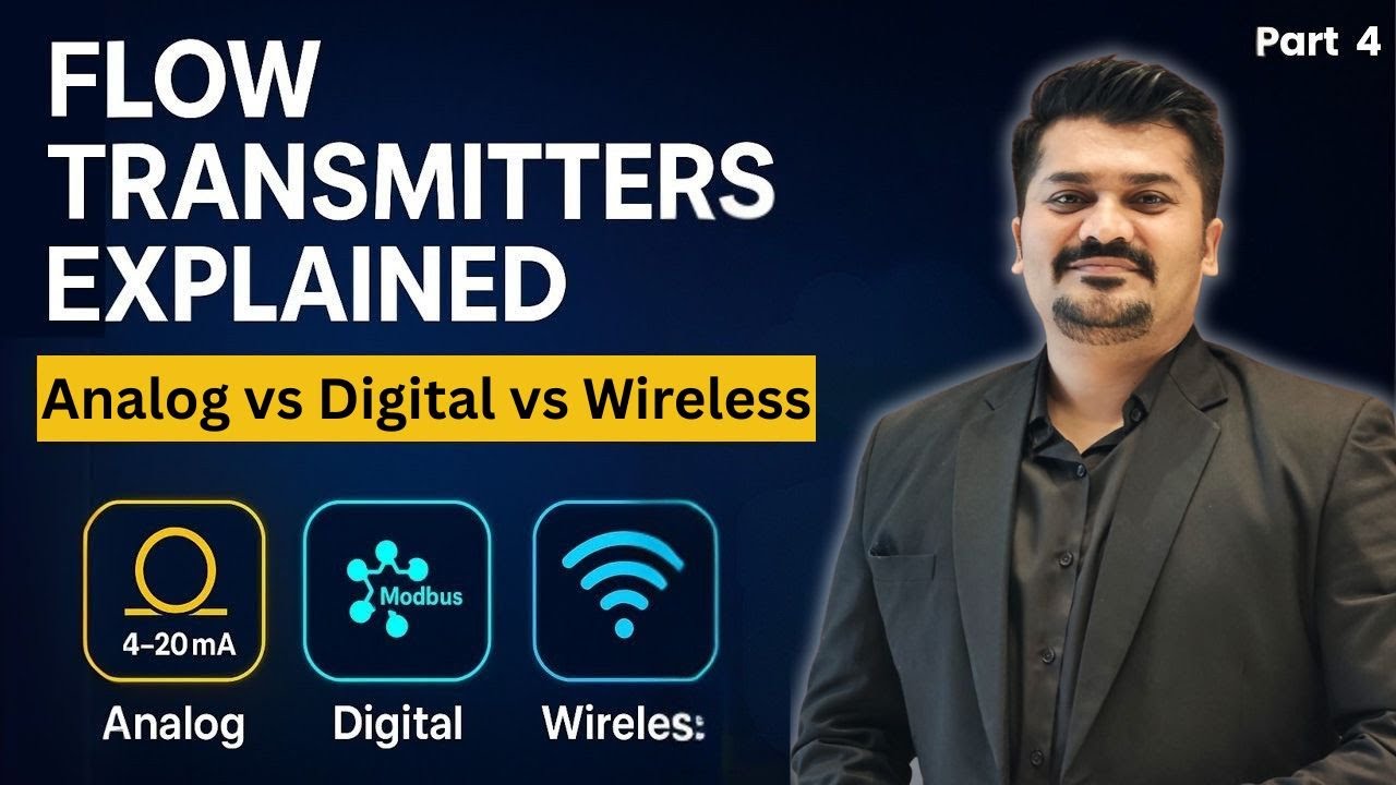
This video breaks down the transit-time measurement principle, signal output types (4–20 mA, Modbus, HART), and integration basics for engineers working with ultrasonic flow data in industrial automation and SCADA systems.
Selecting the Right Ultrasonic Gas Flow Meter: Decision Framework
Use this framework as a starting point for meter selection conversations — it reflects the actual decision criteria used by OEMs, EPCs, and utility procurement teams in high-stakes applications.
| Decision Factor | Key Questions | Impact on Meter Selection |
|---|---|---|
| Application criticality | Fiscal/custody transfer or process monitoring? | Custody transfer requires AGA-9/OIML multipath (≥4 path) |
| Pipe diameter | DN50–DN1200? | Determines path geometry (Z, V, W) and path count |
| Gas composition | Stable pipeline gas or variable/RNG/H₂ blend? | Stable: fixed composition input; Variable: GC integration |
| Pressure rating | Line pressure and test pressure? | Verify ANSI/DIN flange class and body pressure rating |
| Turndown requirement | Max-to-min flow ratio in your operating cycle? | High turndown (>20:1) requires multipath ultrasonic |
| Installation constraints | Available straight-run upstream/downstream? | Limited straight run → multipath with flow conditioning |
| Communication protocol | HART, Modbus, FOUNDATION Fieldbus, or 4–20 mA? | Must match existing DCS/PLC I/O infrastructure |
| Hazardous area | Class I Div 1/2 (NEC) or Zone 1/2 (ATEX/IECEx)? | Requires Ex-certified electronics and housing |
| Environmental rating | Outdoor/wet conditions? | IP66/IP67 rated housing and conduit entry |
| Calibration access | On-site verification possible or must remove meter? | Some designs support in-situ verification via diagnostic output |
Jade Ant Instruments works directly with OEM skid manufacturers, EPC specification teams, and instrument distributors on ultrasonic gas meter selection, sizing, and pre-configured metering package assembly. For technology comparison across ultrasonic, Coriolis, turbine, and other gas measurement technologies, the comprehensive flow meter technology comparison guide provides a structured decision framework matched to application requirements.

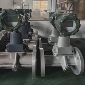
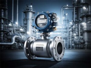
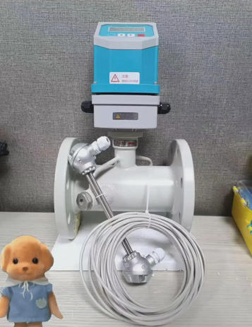
The acoustic transducer ports on an ultrasonic meter are its only interface with the gas — their placement angle, spacing, and alignment determine measurement performance across the meter’s entire operating range.
Glossaire des termes clés
| Terme | Définition en langage clair |
|---|---|
| AGA-9 | American Gas Association Report No. 9 — the industry standard for multipath ultrasonic meters used in natural gas custody transfer measurement |
| AGC | Automatic Gain Control — an electronic circuit that adjusts amplification to maintain a consistent signal level; in ultrasonic meters, increasing AGC indicates degrading transducer signal |
| Chord / Chordal path | The straight-line acoustic path between a pair of transducers in an ultrasonic meter; a 4-chord meter has 4 independent path measurements |
| Transfert de garde | Any gas measurement point where gas ownership or financial responsibility changes hands between parties — the highest-accuracy, most regulated measurement category |
| DCS | Distributed Control System — a central platform that monitors and controls process instruments across a facility |
| Energy flow | The heating value content of gas flowing per unit time (MJ/h or BTU/h) — requires both accurate mass flow and accurate gas composition for heating value calculation |
| Calculateur de débit | Electronic device that combines meter velocity output with pressure, temperature, and composition inputs to calculate corrected volumetric flow, mass flow, and energy flow |
| Gaussian integration | A mathematical technique that approximates the cross-sectional average velocity from a finite number of chord measurements — used by multipath ultrasonic meters to calculate volumetric flow |
| GC | Gas Chromatograph — an instrument that continuously analyzes the individual molecular components of a gas mixture and reports their concentrations |
| HART | Highway Addressable Remote Transducer — a communication protocol that overlays digital data on a standard 4–20 mA analog signal |
| MTBf | Mean Time Between Failure — statistical average operating time between failures; a reliability metric for equipment |
| Nm³/h | Normal cubic meters per hour — gas volume corrected to 0°C and 1.01325 bar reference conditions |
| OIML R137 | International Organization of Legal Metrology Recommendation No. 137 — global standard for gas meters used in legal metrology (billing and fiscal) applications |
| Piezoelectric transducer | A device that converts electrical pulses to ultrasonic sound waves and vice versa — the acoustic element in an ultrasonic flow meter |
| Profile factor | The ratio of average gas velocity (measured across all acoustic paths) to peak velocity (at pipe centerline) — a diagnostic indicator of flow profile symmetry |
| RTD | Resistance Temperature Detector — a precision temperature sensor used for gas temperature compensation in flow calculations |
| SCFH | Standard Cubic Feet per Hour — gas volume corrected to 60°F and 14.696 psia reference conditions (US standard) |
| SNR | Signal-to-Noise Ratio — the ratio of acoustic signal strength to background noise; low SNR indicates contamination, transducer issues, or wet gas |
| Speed of sound | The velocity at which acoustic waves propagate through a gas — dependent on gas composition, temperature, and pressure; the foundation of ultrasonic transit-time measurement |
| Rapport de réduction | The ratio of maximum to minimum measurable flow rate within specified accuracy; a 50:1 turndown means the meter measures accurately from 2% to 100% of its rated maximum flow |
| Transit time | The time an ultrasonic pulse takes to travel between two transducers; the difference between upstream and downstream transit times is the primary measurement variable |
| Z-path / V-path / W-path | Acoustic path geometries in ultrasonic meters: Z = single diagonal pass; V = single reflection; W = double reflection |
Questions fréquemment posées
1. How does an ultrasonic gas flow meter measure flow without moving parts?
It uses pairs of piezoelectric transducers to send ultrasonic sound pulses across the gas stream — one in the flow direction and one against it. Gas moving through the pipe carries sound downstream slightly faster than upstream. The meter measures the time difference between these two travel times (typically in nanoseconds) and converts it to gas velocity using the known acoustic path length and geometry. No rotors, bearings, or diaphragms are involved.
2. Can ultrasonic meters handle wet gas or entrained liquids?
Standard transit-time ultrasonic meters are designed for dry, single-phase gas service. Wet gas — gas carrying liquid droplets or condensate — scatters and absorbs the acoustic signal, degrading SNR and potentially causing path signal loss. For wet gas applications, specialized meters with high-power transducers, reflective multipath geometry, and signal processing designed for wet conditions are available. For general pipeline service, a correctly designed gas scrubber or coalescing separator upstream of the meter is the preferred solution.
3. What is the minimum straight-run requirement to ensure accuracy?
AGA-9 specifies a minimum of 10 nominal pipe diameters (10D) of straight, unobstructed pipe upstream of a multipath ultrasonic meter, and 3D downstream, for installations with standard upstream disturbances (single elbows, reducers). Double elbows out-of-plane increase the upstream requirement to 20D or more. These are minimums — manufacturers may specify additional straight run for specific disturbances. Flow conditioners (perforated plate devices that homogenize the velocity profile) can reduce straight-run requirements, but must be included in the calibration flow direction.
4. How often does an ultrasonic meter need recalibration in field service?
For custody transfer meters, AGA-9 and most regulatory frameworks require periodic verification every 1–3 years — the exact interval depends on jurisdiction, meter size, and operating conditions. For process control and utility metering, 3–5 year intervals are typical for stable clean-gas service. The key advantage of multipath ultrasonic meters is that continuous path-level diagnostic data can demonstrate meter health between calibrations — and in some regulatory frameworks, documented diagnostic stability can extend the calibration interval.
5. Why does my meter show drift when gas composition changes?
Because ultrasonic meters calculate flow using the speed of sound in the gas, and the speed of sound changes with gas composition. If the flow computer is programmed with a fixed gas composition but the actual gas blend has changed — higher CO₂ content, more nitrogen, a hydrogen blend — the meter’s speed-of-sound calculation will be wrong, and the flow output will be systematically offset. The fix is to update the gas composition in the flow computer and, for applications with significant composition variability, integrate a gas chromatograph for continuous composition tracking.
6. Can I use one ultrasonic meter for both natural gas and hydrogen-blended streams?
Many modern multipath ultrasonic meters are firmware-configurable for hydrogen-blended service, but you must verify several things: that the meter’s transducer frequency is appropriate for the speed of sound in the hydrogen blend (which is significantly higher than natural gas), that the flow computer can accept hydrogen fraction as an input variable, and that the meter’s pressure and temperature ratings cover the operating conditions of the hydrogen service. Consult your meter manufacturer with the specific blend percentage and operating conditions — do not assume a natural gas meter is hydrogen-compatible without written vendor confirmation.
7. What input parameters are critical for correct flow calculation?
The flow computer requires four categories of input for accurate corrected flow calculation: (1) gas velocity from the acoustic transit-time measurement; (2) line pressure from a calibrated pressure transmitter; (3) line temperature from a calibrated RTD; and (4) gas composition — either from a fixed programmed value or from a continuous gas chromatograph. An error in any one of these inputs produces a proportional error in the corrected flow output. The acoustic velocity measurement itself is typically the most stable and accurate element; pressure and temperature inputs are the most common sources of systematic drift.
8. How do pressure and temperature transmitters affect overall metering accuracy?
Directly and proportionally. For corrected (standard) volumetric flow, the calculation is: actual flow × (P/P_ref) × (T_ref/T), where P and T are measured values. A 1% pressure measurement error produces approximately a 1% corrected flow error. A 3°C temperature error in a line operating at 20°C (absolute temperature 293K) produces approximately a 1% corrected flow error. In custody transfer applications, specifying PT transmitters with ≤0.1% total error band (accuracy, drift, and temperature coefficient combined) is essential for achieving the overall metering system uncertainty target.
9. Is AGA-9 compliance mandatory for all custody transfer applications?
In North America, AGA-9 compliance is the industry-accepted standard for natural gas custody transfer using ultrasonic meters, and it is referenced in many gas sales contracts and regulatory permits as a contractual requirement. It is not a government regulation in the same way that legal metrology frameworks (like OIML R137 in Europe) are — but a meter that is not AGA-9 certified will face resistance in any fiscal metering application where the counterparty or regulator expects AGA-9 compliance. For international projects, determine which standard governs at the project location: AGA-9 (North America), ISO 17089 (international), or OIML R137 (legal metrology applications in many countries).
10. What diagnostic tools are available to verify meter health remotely?
Modern multipath ultrasonic meters provide extensive remote diagnostic data via HART, Modbus, or dedicated diagnostic software: path-level signal quality (SNR or AGC gain), measured speed of sound vs. expected speed of sound, velocity profile symmetry (profile factor), path velocity ratios (comparing individual paths to detect single-path anomalies), accumulated totals for each path (to identify path-level bias), and electronics health indicators. Advanced users connect this data to SCADA historians and run trend analysis to detect gradual degradation months before it affects measurement accuracy — essentially implementing condition-based maintenance for their metering infrastructure.
11. How do I integrate ultrasonic flow data into my existing DCS or SCADA system?
The most common integration path for existing systems is 4–20 mA for the primary flow variable (corrected volumetric flow) combined with HART for secondary variables and diagnostics — this works on existing wiring infrastructure. For new installations or where multi-variable access is required, Modbus RTU via RS-485 provides access to the full range of flow variables, totals, and diagnostic parameters in a single cable. FOUNDATION Fieldbus or PROFIBUS PA provide the highest integration depth in advanced DCS environments but require bus infrastructure. Whichever protocol you specify, verify the exact Modbus register map or HART DD (Device Description) file with the meter manufacturer before DCS configuration begins.
12. What are the differences between multipath and single-path ultrasonic meters?
A single-path meter uses one pair of transducers and measures gas velocity at one position across the pipe — fast, low-cost, but highly sensitive to flow profile distortion and limited to lower accuracy (±1–2%). A multipath meter uses 4–8 pairs of transducers arranged at different positions across the pipe cross-section, averaging velocity measurements using Gaussian integration to produce a much more accurate cross-sectional mean velocity. Multipath meters also provide path-level diagnostics — comparing individual paths to detect contamination, flow disturbance, or individual transducer degradation. AGA-9 custody transfer applications require multipath meters.
13. Can ultrasonic meters be used for bidirectional flow in pipeline reversals?
Yes — this is one of the definitive advantages of ultrasonic meters over turbine and orifice meters. Because the transit-time measurement principle measures both upstream and downstream transit times simultaneously, the meter can determine flow direction and magnitude equally well in either direction. The flow computer must be configured for bidirectional operation, and the output system must handle positive and negative flow values correctly. Many pipeline systems that experience seasonal flow reversal (where gas flows in the opposite direction depending on regional supply and demand conditions) have replaced turbine meters specifically because turbine meters cannot handle reverse flow without damage.
14. What causes signal loss in ultrasonic meters, and how can it be prevented?
Path signal loss (where one or more acoustic paths produces insufficient SNR for reliable measurement) is caused by: (1) transducer face fouling from hydrocarbon deposits or particulate — prevented by upstream gas conditioning (filtration, coalescing separation); (2) liquid slugs or wet gas episodes — detected by SNR trend monitoring and prevented by process design (scrubbers, appropriate operating temperature above dew point); (3) acoustic noise from turbulent flow at very high velocities or from nearby control valves — mitigated by velocity-appropriate meter sizing and valve placement at minimum 5D from the meter; (4) internal bore coating — detected by profile factor trending and prevented by gas quality management upstream.
15. How do I size the right ultrasonic meter for high-pressure transmission lines?
Size the meter for the actual flow velocity, not just the volumetric flow rate. At high operating pressure, gas density is high — so the same mass flow rate produces a much lower actual velocity than at lower pressure. Recommended velocity ranges for ultrasonic meters are typically 0.5–30 m/s for standard applications, with some high-velocity designs rated to 40 m/s. A meter sized for maximum flow should produce a velocity in the upper third of its rated range at maximum flow, and should remain above the minimum velocity threshold (typically 0.5 m/s) at the minimum design flow. For high-pressure applications, also verify the meter’s pressure body rating (ANSI Class 600, 900, or 1500) and the transducer pressure seals against both operating and hydrostatic test pressure requirements.
16. Are there cost advantages over turbine or Coriolis meters in large-diameter lines?
Significant ones, for large pipe sizes. In lines DN200 and above, turbine meter cost scales roughly with pipe cross-sectional area — a DN500 turbine meter suitable for high-pressure custody transfer costs $30,000–$60,000 and requires annual bearing inspection. The equivalent ultrasonic multipath meter costs $15,000–$40,000 and has a 3–5 year maintenance interval. The pressure drop advantage is even more economically significant at high throughput: an orifice plate on a major transmission pipeline may cause enough pressure drop to require $80,000–$150,000/year in additional compression energy. An ultrasonic meter creates negligible pressure drop — that energy savings alone typically pays the cost difference within 12–18 months.
17. What certifications are needed for use in hazardous (Class I Div 1) areas?
For North American applications in Class I Division 1 locations (environments where flammable gases are present under normal operating conditions), the meter must carry UL or FM approval for the specific gas group (Group C/D for natural gas, Group A/B for hydrogen). For international applications, ATEX Zone 1 certification (European) and IECEx certification (international) are the equivalents. Verify that the certification covers the entire meter assembly — electronics housing, conduit entries, and all cable connections — not just the meter body. For Class I Division 1 applications with hydrogen-blended gas, explicitly confirm with the manufacturer that the certification covers hydrogen (Gas Group A/B in NEC classification) rather than only natural gas (Group D).
18. How does fouling or coating inside the pipe affect measurement accuracy?
Internal bore fouling changes the effective pipe ID (which directly affects the volumetric flow calculation) and alters the velocity profile near the pipe wall (which affects the accuracy of Gaussian integration in multipath meters). A 2mm buildup on the interior of a DN200 meter (which has a 200mm nominal bore) reduces the flow area by approximately 4% — producing approximately a 4% flow overestimation if the meter is still calculating based on the original bore area. Bore fouling is best detected by trending the profile factor (ratio of average to centerline velocity) — this changes as the wall boundary layer becomes irregular from fouling deposits.
19. Can ultrasonic meters operate reliably in low-flow or turndown-intensive applications?
Multipath ultrasonic meters excel in turndown-intensive applications — their 50:1 to 100:1 turndown ratio is one of the features that makes them the preferred choice for city gate stations with large seasonal demand variation. At very low flow velocities (below approximately 0.3–0.5 m/s depending on model), signal-to-noise performance degrades and measurement uncertainty increases. For applications where very low flows must be accurately measured, specify a smaller meter diameter to maintain adequate velocity (velocity = flow rate ÷ pipe area; smaller pipe → higher velocity at the same flow rate) and verify the manufacturer’s minimum velocity specification against your minimum design flow condition.
20. What support do manufacturers provide for configuration and commissioning?
Leading ultrasonic gas meter manufacturers provide: factory pre-configuration of the flow computer with application-specific settings (gas composition, reference conditions, output scaling) reducing on-site commissioning time; dedicated commissioning software for verifying path diagnostics, signal quality, and configuration parameters; factory-witnessed flow calibration with uncertainty documentation for AGA-9 or ISO 17089 compliance; remote diagnostic support during commissioning via secure connection to the meter’s communication port; and application engineering support for sizing, selection, and integration design. Jade Ant Instruments provides application engineering support for ultrasonic gas flow meter selection, pre-commissioning configuration, and field troubleshooting guidance as part of the supply relationship — not as a post-sale service engagement.
External references used in this guide:
- Cherokee Tulsa — What Is an Ultrasonic Gas Flow Meter?
- AGA Report No. 9 — Measurement of Gas by Multipath Ultrasonic Meters (AFMS)
- Flowell — Ultrasonic vs. Differential Pressure Flow Meters: TCO Comparison
- Fuji Electric Americas — How Multipath Ultrasonic Flowmeters Improve Accuracy in Large Pipelines
- Emerson — Hydrogen Measurement with Ultrasonic Flow Meters
- Mustang Sampling — Measurement and Analysis in the Evolving RNG Market
- Turbines Incorporated — What Is Flow Meter Turndown and Why It Matters
- Industrial Monitor Direct — Flow Meter Straight Run Requirements
- Kobold USA — International Standards for Instrumentation in Hazardous Areas
- Jade Ant Instruments — Ultrasonic vs. Magnetic vs. Turbine Flow Meter Guide