When Your Customers’ Operations Depend on Accuracy: Why Gas Flow Meter Troubleshooting Matters to Your Bottom Line
Your phone rings at 7:45 AM. A plant manager you’ve supplied for three years tells you their gas flow meter is showing readings 9% below what their supplier is billing them for. Production is running. The accounting team is escalating. They need answers, and they need them from you — not from a manufacturer’s generic support line.
That moment — not the initial sale — is where distributor reputations are made or destroyed.
Gas flow meter troubleshooting isn’t a skill that belongs exclusively to the end-user’s maintenance team. For distributors and agents who supply flow instrumentation, the ability to diagnose problems quickly, guide customers through systematic checks, and know when to escalate versus when to resolve in-house is a direct commercial advantage. Every service call you handle competently is a customer retained. Every call you fumble is a competitor’s opening.
This guide is written entirely for flow instrumentation distributors and agents — the people in the channel between manufacturers and industrial end-users. It covers the systematic diagnostic approach, the most common failure patterns by type, and the operational strategies that transform reactive troubleshooting into a proactive service capability that differentiates your business.
1. Understanding the Root Causes: Why Gas Flow Meters Fail
The Four Primary Failure Categories Affecting Your Customer Base
Before touching a diagnostic tool, understand this: the overwhelming majority of gas flow meter failures fall into four categories. Knowing which category a problem belongs to before you start troubleshooting cuts resolution time by 60–70% and prevents the most common diagnostic error — fixing the symptom while missing the actual cause.
Calibration Drift and Accuracy Loss
Calibration drift — the gradual deviation of a meter’s measured output from its true value — is the single most reported issue in gas flow instrumentation field service. It is also the most misunderstood, because drift is rarely catastrophic. It accumulates slowly, often over months, until the measurement error crosses a threshold that becomes operationally or commercially visible.
Why meters lose calibration over time: Gas flow meters are exposed to process conditions that progressively alter their measurement characteristics. In thermal mass flow meters (devices that infer mass flow from the heat transfer between a heated element and the gas stream), long-term exposure to process gas contaminants — even trace amounts of oil vapor, moisture, or particulate — gradually coats the sensing element and alters its thermal response. A meter that measured ±1% accuracy on commissioning day can drift to ±3.5% accuracy 18 months later with no visible change in operation. In turbine meters, bearing wear changes the relationship between rotor speed and actual volumetric flow — a K-factor (the calibration constant expressing pulses per unit volume) that was set at 847 pulses/liter on calibration day may be functionally operating at 831 pulses/liter a year later without triggering any alarm.
How environmental factors contribute: Temperature cycling — particularly in outdoor installations or facilities near furnaces — causes thermal expansion and contraction of meter body components. In vortex flow meters (which measure flow by counting the frequency of vortices shed from a bluff body in the flow stream), dimensional changes in the bluff body alter the Strouhal number relationship used to calculate flow velocity. This is not a manufacturing defect; it is physics. It means meters in thermally demanding environments need more frequent recalibration than meters in stable environments.
What accuracy tolerances matter for different gas types: For natural gas custody transfer (where ownership changes between parties), the standard API MPMS Chapter 5 requires measurement uncertainty of ±0.25% or better. For general plant utility gas monitoring, ±2% is often acceptable. For regulatory emissions reporting under EPA 40 CFR Part 75, accuracy requirements vary by pollutant but are typically ±5% of measured value. Knowing your customer’s tolerance threshold helps you determine when drift constitutes an urgent problem versus a scheduled maintenance item.
Red flags that indicate recalibration is overdue: Watch for these patterns in customer reports — consistent discrepancy between the gas meter and their supplier’s invoice (not fluctuating, but persistently one direction); new discrepancies after a process change that altered gas temperature or composition; or readings that were stable for two years and have begun drifting gradually over the last three months.
Sensor and Detection Malfunctions
Sensor failures are distinct from calibration drift. Where drift is gradual and often reversible through recalibration, sensor degradation is progressive structural damage to the measurement element itself.
Common sensor degradation patterns: Thermal mass flow sensors develop contamination layers — oil vapor deposits, fine particulate coatings, or moisture films — that insulate the heated sensing element and reduce its sensitivity to gas velocity changes. In ultrasonic gas flow meters (which use sound wave travel time to measure velocity), the transducer faces can accumulate deposits in applications involving gas streams carrying hydrocarbon aerosols, which attenuate the acoustic signal and reduce signal-to-noise ratio.
How contamination affects sensor performance: A contaminated thermal sensor doesn’t fail abruptly; it produces readings that appear plausible but are systematically low, because the contamination layer requires more heat input to maintain the sensor’s target temperature differential — altering the relationship between heater power and gas mass flow. Customers experiencing this often attribute the low readings to process changes rather than sensor degradation, delaying diagnosis.
Temperature and pressure fluctuations as hidden culprits: Rapid thermal cycling — common near compressor discharge points or heat exchanger outlets — causes mechanical fatigue in piezoelectric sensing elements used in vortex and ultrasonic meters. Pressure surges from pump starts or valve operations create hydraulic shock that can physically damage delicate sensor assemblies.
Why preventive sensor maintenance saves your customers money: A scheduled sensor cleaning on a thermal mass flow meter costs approximately $200–400 in labor and materials. An unplanned sensor replacement after contamination-induced failure costs $800–2,500 for the sensor plus $1,500–5,000 in downtime depending on industry. The financial argument for preventive sensor maintenance is not subtle — it’s a 5:1 to 10:1 return on investment that your customers will appreciate having quantified for them.
2. Diagnostic Protocol: The Systematic Approach Your Customers Expect
Establishing a Baseline Before Troubleshooting Begins
The most common mistake in gas flow meter diagnostics is jumping to a solution before fully understanding the problem. A meter showing erratic readings could be caused by six completely different issues — blockage, electrical interference, incorrect gas type programmed, failing sensor, upstream flow disturbance, or a legitimate process change. Each has a different fix. Guessing is expensive.
Gathering Critical Information from Your Customer
Start every diagnostic engagement with a structured information-gathering conversation. This is not bureaucracy; it is the fastest path to the right answer.
Essential questions about meter history and installation:
- What is the meter model, serial number, and installation date?
- When did the problem first appear — and did anything change in the plant the day before or week before it started?
- Has this meter been recalibrated since installation, and if so, when?
- Has anyone made configuration changes to the meter recently?
Understanding the specific gas type and flow range: What gas is being measured? At what operating pressure? At what temperature? What is the normal operating flow rate, and what was it reading when the problem started? These parameters determine which failure modes are physically plausible.
Identifying recent operational changes: “Nothing changed” is almost never true. Probe deeper — was there a new compressor installed upstream? Did the gas supplier change the blend? Was there a plant shutdown and restart? Was there a welding or cutting operation in the adjacent piping? Each of these can trigger measurement anomalies that look like meter failure but are process changes.
Documenting ambient conditions: For outdoor installations or facilities in climates with significant seasonal temperature swings, note the current and recent ambient temperature range. A meter calibrated in summer and now operating in a cold winter environment may be experiencing temperature effects that explain the discrepancy.
Performing Pre-Diagnostic Checks
Before any instrument testing, complete this visual and functional checklist with your customer or field technician:
Visual inspection checklist:
- Is the meter body physically undamaged — no dents, cracks, or corrosion on the body or process connections?
- Are all cable entries and conduit connections sealed properly — no evidence of moisture ingress?
- Is the flow arrow on the meter body aligned with the actual direction of gas flow in the pipe?
- Are all display screens and indicator lights functioning normally?
- Is there any visible condensation on the display or inside the electronics housing?
Verifying power supply and electrical connections:
- Confirm supply voltage at the meter terminals against the nameplate specification (typically 24VDC ±10% or 110/230VAC).
- Check that all wiring connections are secure and that terminal screws have not vibrated loose.
- Verify grounding: poor earth grounding is a leading cause of erratic signal outputs in electronically compensated gas meters.
Confirming installation alignment and positioning: Check that the required upstream and downstream straight-pipe runs are maintained (most gas flow meters require 10–20 pipe diameters upstream and 5 pipe diameters downstream of straight, undisturbed pipe). Any valve, elbow, tee, or reducer within this distance can disturb the velocity profile and introduce measurement error.
Testing display and data transmission: Compare the local display reading against the output at the receiving instrument (DCS, PLC, flow computer). A discrepancy between what the meter displays and what the control system receives indicates an output signal issue — not a measurement accuracy problem.
3. Tackling Calibration Errors: The Most Common Complaint
Identifying When Calibration Is Actually the Problem
Recognizing Calibration Drift Symptoms
Calibration errors are deceptively straightforward to identify — when you know what distinguishes them from other failure types.
Unexplained reading discrepancies: If a meter consistently reads 6% lower than the supplier’s invoice across multiple billing periods, and the discrepancy is stable rather than fluctuating, calibration drift is the most likely cause. The key word is “consistently.” Calibration drift produces systematic bias — always in the same direction, roughly the same magnitude. Sensor blockage or electrical noise produce erratic readings. Know the difference.
Inconsistent measurements across similar operating conditions: If a meter reads accurately at mid-range flow but shows increasing error at low or high flows, the problem is often a linearization error in the calibration — the calibration curve that translates the raw sensor signal into a flow reading is not accurately representing the meter’s behavior across its full range.
Comparison testing against known standards: The most reliable calibration verification is a portable reference meter — a clamp-on ultrasonic meter on the same pipe section, or a master meter in a test loop — run simultaneously with the suspect meter. A 3% discrepancy between the reference and the installed meter is measurable and actionable. Without a reference, you’re relying on customer reports rather than independent measurement.
When recalibration is the solution versus when it’s a symptom: If recalibration restores accuracy and the meter holds calibration for 12+ months, the issue was simple drift. If the meter returns out of calibration within weeks of recalibration, something is causing accelerated drift — contamination, thermal stress, or a failing sensor element. Recurring calibration failures require investigation of root cause, not repeated recalibration.
Step-by-Step Recalibration Procedures
Pre-calibration preparation: Before recalibration, the meter and its sensing elements must be clean. On thermal mass flow meters, this means inspecting and if necessary cleaning the sensor (follow the manufacturer’s specific cleaning procedure — solvent type and method vary by sensor design). On ultrasonic meters, inspect the transducer faces and clean if contaminated. Attempting to calibrate a contaminated sensor produces a calibration that accurately represents the contaminated sensor’s performance — not the clean sensor’s performance.
Using reference standards appropriate for your customer’s gas type: Calibration for natural gas service is not valid for compressed air service because the acoustic properties, heat capacity, and viscosity of these gases are fundamentally different. Meters must be calibrated with their actual service gas, or with a certified substitution gas and an appropriate conversion factor applied. This is a common mistake that distributors must understand and communicate clearly.
Documenting baseline readings before adjustment: Always record the “as-found” reading before any calibration adjustment. This establishes the magnitude of drift that occurred since the last calibration — information that informs maintenance interval decisions and provides documented evidence if warranty claims arise.
Post-calibration verification and acceptance criteria: After calibration adjustment, verify accuracy at three flow points: minimum (approximately 10% of maximum rated flow), midrange (50%), and maximum (100%). All three should be within specification before issuing a calibration certificate. A meter that passes at midrange but fails at low flow has not been properly calibrated.
Creating calibration records your customers can trust: Every calibration should produce a certificate that includes: meter identification (model, serial, tag number), calibration date, calibration standard used (with traceability reference), as-found deviation, adjustment made, as-left reading at each test point, technician name, and next recalibration due date. Customers who receive this documentation — without having to ask for it — have a tangible measure of your professionalism.
4. Sensor Troubleshooting: Diagnosing Detection Problems

When Sensors Stop Responding Accurately
Common Sensor Failure Patterns and What They Mean
Thermal sensor degradation in high-temperature applications: Thermal mass flow meters (also called calorimetric meters) use paired resistance temperature detector (RTD) elements — one heated, one at ambient — to infer mass flow from the heat carried away by the gas. At elevated temperatures (process gas above 200°C), the heated element’s resistance characteristics shift with thermal cycling, eventually producing a permanent offset. Customers typically report this as “the meter reads low even at high flow” — because the sensor’s sensitivity is reduced, it reports less mass flow than is actually occurring.
Pressure sensor drift and hysteresis issues: In gas flow meters with integrated pressure sensors for compensation (more on this in Section 6), piezoresistive pressure sensors develop hysteresis — a condition where the sensor’s output depends not just on the current pressure but on the recent history of pressure changes. A sensor that reads accurately when pressure is increasing may read 0.5–1.5% low when pressure is decreasing through the same range. This creates apparent measurement oscillation that is actually a sensor characteristic rather than a process event.
Ultrasonic sensor blockage and acoustic interference: Ultrasonic gas flow meters measure the time difference of acoustic pulses traveling upstream and downstream through the gas. When hydrocarbon liquid dropout — condensate forming on the pipe wall — contacts the transducer faces, acoustic coupling changes, signal amplitude drops, and the meter’s signal processing algorithms struggle to distinguish valid measurement signals from noise. The symptom is erratic readings or “flow loss” errors even when actual flow is present and continuous.
Vortex shedding sensor fouling in contaminated gas streams: Vortex flow meters measure flow by counting the frequency of vortices shed from a bluff body obstruction in the pipe. The piezoelectric or capacitive sensor that detects these vortices is located inside the bluff body or on the pipe wall adjacent to it. In gas streams carrying traces of compressor oil, heavy hydrocarbon vapor, or pipe scale, this sensor face gradually accumulates deposits that dampen the sensor’s mechanical response to vortex pressure pulses — reducing sensitivity until, at sufficient deposit thickness, the meter stops detecting vortices at low flow rates entirely.
Practical Testing Procedures for Sensor Validation
Resistance and continuity testing for electrical sensors: For RTD-based thermal sensors, measure resistance at the sensor terminals and compare against the manufacturer’s reference table for the current ambient temperature. A PT100 RTD should read approximately 100Ω at 0°C and 138.5Ω at 100°C. Deviation greater than ±0.5Ω from the reference table at a known temperature indicates sensor degradation.
Response time verification: Apply a step change in flow (by briefly throttling a downstream valve and then releasing) and observe how quickly the meter reading responds and stabilizes. A healthy sensor reaches 90% of the new steady-state value within the manufacturer’s specified response time (typically 1–3 seconds for thermal meters, <1 second for vortex and ultrasonic). Sluggish response — taking 10+ seconds to stabilize after a flow change — indicates a contaminated or degraded sensor.
Comparative testing against backup meters: The most operationally practical sensor validation is a parallel measurement — a portable clamp-on ultrasonic meter on the same pipe section, reading simultaneously. A comparison at three flow rates takes 30 minutes and produces definitive evidence of whether the installed meter’s sensor is reading correctly.
When sensor replacement is more cost-effective than repair: If resistance testing confirms sensor degradation and cleaning does not restore performance to specification, the decision framework is: replacement sensor cost versus the ongoing cost of operating on an out-of-spec meter. For a gas billing meter accumulating 0.5% error per month on a $50,000/month gas bill, the monthly billing error is $250. A $600 replacement sensor pays back in 2.4 months. Frame this calculation for your customer; they will make the right decision.
5. Flow Obstruction and Blockage Issues: Quick Wins for Your Customers
Clearing the Path: Identifying and Removing Obstructions
Obstruction is the most immediately resolvable category of gas flow meter failure — and often the most satisfying for your customer, because the fix is definitive and the meter returns to normal operation immediately. It is also the most preventable, which makes recurring obstruction issues a signal that the customer’s upstream filtration and system preparation practices need attention.
Recognizing Blockage Symptoms
Sudden, unexplained flow rate drops: If a meter goes from normal readings to near-zero or abnormally low readings within a short time (hours to a day), obstruction is the leading hypothesis. Calibration drift doesn’t happen overnight. Sensor degradation is gradual. A sudden step-change in reading points to a physical event — contamination arriving at the meter, condensation forming on a transducer face, or scale detaching from the upstream pipe and lodging in the meter body.
Pressure buildup before the meter: A portable pressure gauge tapped immediately upstream of the meter, compared against the normal operating pressure, will confirm obstruction. If upstream pressure is elevated above normal and downstream pressure is depressed, something is restricting flow through the meter body. The pressure differential across the meter quantifies the severity of the restriction.
Inconsistent readings that improve after shutdown: Some obstructions — particularly condensate films on ultrasonic transducer faces — partially resolve when the meter is de-energized and the transducer surfaces return to ambient temperature. If a customer reports that their meter reads poorly during operation but appears to recover after shutdown, condensation-related obstruction is likely.
Gas quality indicators that suggest contamination: If your customer’s gas stream periodically carries entrained liquid (natural gas systems during cold snaps, steam systems during pressure fluctuations, compressed air systems with inadequate dryers), these liquid slugs will arrive at the meter and either coat sensor surfaces or, in extreme cases, fill the meter body temporarily. Gas quality records or moisture content data from the supplier can confirm whether liquid contamination is plausible.
Safe Removal Procedures
Proper isolation and depressurization protocols: Before any internal inspection or cleaning of a gas flow meter, the line must be properly isolated, depressurized, purged, and gas-freed according to the site’s lock-out/tag-out procedures. This is non-negotiable. Document this requirement explicitly in every troubleshooting instruction you provide to customers.
Identifying what’s blocking the sensor:
- Scale and pipe debris: Brown or gray granular deposits — iron oxide scale from upstream pipework, mill scale from new installations — accumulate in the low-velocity zones of the meter body.
- Compressor oil deposits: Amber or dark brown viscous residue on thermal sensor elements or ultrasonic transducer faces. The source is almost always inadequate oil/gas separation downstream of the compressor.
- Condensate (liquid water or hydrocarbon): Clear to slightly colored liquid pooling in the meter body. Common in natural gas systems, particularly during ambient temperature drops.
- Pipe thread sealant or PTFE tape fragments: Surprisingly common in new installations where thread sealant was over-applied or wrapped incorrectly.
Cleaning procedures appropriate for different meter types: Ultrasonic transducer faces can be cleaned with isopropyl alcohol and a lint-free cloth — never abrasive materials. Thermal mass flow sensor elements require manufacturer-specified cleaning agents and procedures; incorrect solvents can strip sensor element coatings. Vortex bluff bodies can typically be cleaned with a soft brush and appropriate solvent, with the body removed from the process pipe per the manufacturer’s procedure.
When to recommend system-wide filtration improvements: Recurring obstruction is a system problem, not a meter problem. If a customer experiences contamination-related meter issues more than once per year, the answer is an upstream coalescing filter or gas conditioning unit — not repeated meter cleaning. Position this recommendation not as an upsell but as a genuine solution: “Your meter will keep experiencing this until we address what’s coming down the pipe.”
6. Temperature and Pressure Compensation: The Often-Overlooked Factor
How Environmental Conditions Mask Real Problems
Understanding Compensation System Failures
Temperature and pressure compensation — the process by which a gas flow meter corrects its volumetric measurement to a standard reference condition (typically 0°C or 15°C, at 1 atm) — is one of the most critical and most frequently misunderstood elements of gas flow measurement. When compensation works correctly, it is invisible. When it fails or is incorrectly configured, it produces systematic errors that can look like meter failure, calibration drift, or sensor problems — frustrating troubleshooting efforts until the compensation system is specifically interrogated.
Gas is compressible: its volume changes with both temperature and pressure. A cubic meter of natural gas at 10 bar and 40°C contains approximately 9.3 times the mass of gas as a cubic meter at 1 bar and 20°C. A flow meter measuring volumetric flow at actual process conditions without applying correction will report volumes that change with process temperature and pressure — even when the actual mass flow hasn’t changed at all.
When built-in temperature compensation stops working: Gas flow meters with integrated temperature sensors use an RTD or thermocouple inserted into the gas stream to provide real-time temperature data for compensation calculation. If this temperature sensor fails — or more commonly, develops drift — the compensation continues to operate, but with incorrect temperature input. The meter will report volumetric flow that is systematically high in cold conditions (because it’s compensating for a temperature warmer than actual) and systematically low in warm conditions. Customers experiencing a problem that is “worse in winter” should immediately trigger a temperature sensor check.
Pressure-dependent measurement errors: A 30% pressure swing produces approximately a 30% mass flow error in uncompensated systems. In natural gas distribution networks where line pressure varies between 200 mbar (low-pressure distribution) and 4 bar (medium-pressure), uncompensated or incorrectly compensated measurement can produce errors exceeding 20 times the meter’s intrinsic accuracy specification. The compensation system is not a refinement — it is fundamental to accurate gas measurement.
Gas density variations that affect mass flow readings: Thermal mass flow meters measure mass flow directly, inferring it from heat transfer characteristics. Those characteristics are specific to the gas being measured — a meter calibrated on pure methane will read incorrectly on a natural gas blend with significant propane or ethane content, because the heat capacity and thermal conductivity of the blend differ from methane. This is not a meter failure; it is a configuration issue. But customers experience it as a measurement problem.
Why your customer’s readings don’t match their supplier’s: The most common cause of customer-supplier measurement discrepancy is a difference in measurement reference conditions. The customer’s meter may be reporting volume at actual operating conditions; the supplier’s metering station is reporting volume corrected to standard conditions. If neither party’s technical team recognizes this, the investigation can consume days and damage relationships unnecessarily. Always check measurement reference conditions before investigating meter performance.
Verifying Compensation Accuracy
Testing temperature sensor functionality: Using a calibrated handheld thermometer at the temperature sensor insertion point, compare the measured temperature against the value shown on the meter’s diagnostic display. A discrepancy greater than ±1°C for standard measurement applications (±0.5°C for billing applications) indicates the temperature sensor requires recalibration or replacement.
Validating pressure transducer readings: Connect a calibrated reference pressure gauge to the nearest accessible pressure tap and compare against the value shown in the meter’s diagnostic menu. Pressure transducer drift of more than ±0.5% of span requires recalibration.
Comparing compensated versus uncompensated readings: Most modern gas flow meter displays allow you to switch between actual flow (uncompensated) and standard flow (compensated) display modes. Running both simultaneously, while monitoring process temperature and pressure with reference instruments, is the definitive test of whether the compensation system is functioning correctly.
Adjusting compensation settings for seasonal variations: In applications where the gas temperature varies significantly by season — outdoor installations, gas supply to seasonal heating systems — verify that the meter’s compensation is being applied dynamically (using live temperature data from its sensor) rather than using a fixed temperature value programmed at installation. A fixed compensation value set during summer commissioning will produce systematic under-reporting of mass flow in winter, when actual gas temperature is lower.
7. Electrical and Communication Issues: When It’s Not the Meter Itself
Troubleshooting Power and Signal Problems
Diagnosing Electrical Failures
One of the most valuable insights experienced field technicians develop is this: most “meter failures” are not meter failures. They are power supply problems, grounding faults, cable damage, or communication configuration errors. Before assuming the measurement device has failed, eliminate the electrical and communication infrastructure as sources of the problem.
| Symptôme | Most Likely Electrical Cause | First Check |
|---|---|---|
| Display blank, no readings | Power supply failure | Verify voltage at meter terminals |
| Erratic, jumping readings | Grounding fault or EMI | Check earth continuity, cable shielding |
| Reading frozen at last value | Signal cable break | Check cable continuity, connector integrity |
| DCS shows wrong value vs display | Output scaling error | Check 4–20mA output calibration at meter |
| Communication timeout errors | Protocol mismatch or address conflict | Verify baud rate, parity, device address |
| Intermittent signal loss | Connector corrosion | Inspect all connectors for moisture/oxidation |
Voltage supply verification and grounding issues: Measure DC supply voltage at the meter terminal block with a calibrated multimeter. For 24VDC loop-powered meters, acceptable range is typically 18–30VDC. Voltage below 18VDC causes erratic operation in many meters; voltage above 30VDC can damage electronics. Grounding quality matters enormously for signal accuracy — an ungrounded or poorly grounded flow meter in an industrial facility with variable-speed drives or welding equipment nearby is subject to electrical interference that produces apparent reading fluctuations.
Battery backup functionality: For remotely installed or wireless gas meters with battery backup, note that battery life is temperature-dependent. A battery rated at 5 years at 20°C may only last 2.5 years at sustained ambient temperatures below -10°C. Check battery voltage against the manufacturer’s replacement threshold before concluding the meter itself has failed.
Connector corrosion and weatherproofing failures: Outdoor installations, particularly in coastal environments or facilities with significant chemical vapor in the atmosphere, are prone to connector corrosion. Green or white powder on cable entry connectors, discoloration of terminal block screws, or moisture inside the electronics housing are all indicators of weatherproofing failure. Clean corroded terminals with contact cleaner, re-seal weatherproof cable entries, and document the date to anticipate future maintenance.
Cable integrity and shielding problems: Signal cables carrying the 4–20mA output from a gas flow meter must maintain their shielding integrity to reject electrical interference. Damaged shielding — from mechanical abrasion, rodent damage, or heat exposure — allows pickup of noise from adjacent power cables, variable-frequency drives, or radio frequency sources. The symptom is characteristically a 50Hz or 60Hz ripple superimposed on the signal, visible as a constant small oscillation in the displayed reading.
Resolving Data Transmission and Display Issues
Serial communication protocol verification: Industrial gas flow meters communicate via standardized protocols — HART (Highway Addressable Remote Transducer), Modbus RTU/TCP, or PROFIBUS. HART allows digital diagnostic data to be overlaid on the standard 4–20mA signal; Modbus and PROFIBUS are fully digital communication buses. Communication failures between meter and control system are almost always caused by configuration mismatches: wrong baud rate, incorrect parity setting, wrong device address, or bus termination errors. Check all four parameters systematically before concluding that hardware has failed. For a detailed reference on communication protocol troubleshooting, Turbines Incorporated’s communication protocols guide is a practical technical resource.
Wireless signal strength and interference problems: WirelessHART and Zigbee-based wireless gas meters are increasingly common in hard-to-wire locations. When customers report intermittent communication with wireless meters, the investigation sequence is: signal strength at the meter (check the RSSI value in the diagnostic menu), obstacles between the meter and gateway (metal cabinets, structural steel, equipment added since installation), and radio frequency interference sources (new wireless equipment, changed operating schedules for existing RF sources).
Display error codes and what they actually mean: Every major gas flow meter manufacturer uses a system of alphanumeric error codes displayed when the meter detects an anomaly. These codes are invaluable diagnostic shortcuts — but only if you have the code translation table. Ensure your technical support files include the error code reference for every meter brand you supply. Common code categories: power supply fault (Exx), communication fault (Cxx), sensor out of range (Sxx), flow out of range (Fxx). Knowing the category immediately focuses the investigation.
8. Installation and Configuration Errors: Prevention as Your Advantage

Insufficient upstream straight-pipe run is the single most common installation error — and it produces systematic measurement error from day one that is never “fixed” by recalibration.
How Improper Setup Creates Problems Down the Road
Identifying Installation-Related Issues
Installation errors are unique among failure categories because they are present from commissioning day — but their consequences often don’t manifest until weeks or months later when the customer notices a pattern they can no longer explain away.
Flow direction reversal: This is more common than it should be, particularly in multi-vendor projects where drawings change between engineering and construction phases. A gas flow meter installed backwards will typically read zero or a very low value, because its measurement algorithm depends on signal direction. Some meter types — bidirectional ultrasonic meters — will actually produce a reading, but with the wrong sign, and potentially without triggering any alarm. Always verify flow direction alignment during commissioning, and include a flow direction verification step in your pre-delivery checklist documentation.
Incorrect meter orientation affecting measurement accuracy: Many gas flow meters have specific orientation requirements. Thermal mass flow meters typically require the heated sensor to be on the downstream side of the sensor pair in a horizontal installation — inverting this relationship changes the thermal response characteristics. Vortex meters require correct orientation relative to the bluff body geometry to maintain their calibrated performance. Condensate in some gas streams can also pool in the bottom of a horizontal pipe section, coating sensors in a way that a vertical installation would avoid.
Inadequate straight-pipe requirements causing flow disturbance: A gas flow meter measures velocity at a specific cross-section of pipe and extrapolates total volumetric flow based on the assumption of a fully developed velocity profile. When an elbow, valve, tee, or reducer is located too close to the meter inlet, the velocity profile is distorted — higher velocity in some zones, lower in others — and the meter’s single-point or limited multipoint measurement does not represent the true average. The result is systematic measurement error that no amount of calibration can correct, because the problem is not with the meter’s measurement of the local velocity — it is with the representativeness of that local measurement. Consult the manufacturer’s straight-pipe requirements (typically expressed as multiples of pipe diameter: “10D upstream, 5D downstream”) before confirming any installation design.
Vibration and mounting issues: Vortex flow meters are the technology most sensitive to external vibration. A plant engineer installing a vortex meter on a pipe bracket adjacent to a reciprocating compressor may create an installation where the compressor’s vibration frequency couples into the vortex meter’s sensor, producing phantom readings. If a customer reports that their gas meter reads flow when the process is shut down, external vibration exciting the vortex sensor is a strong candidate cause.
Configuration Mistakes That Haunt Your Customers
Wrong gas type programmed: Thermal mass flow meters, Coriolis meters, and some ultrasonic meters with density computation require the gas type or gas properties (heat capacity, density at reference conditions, viscosity) to be programmed into their configuration. A meter programmed for pure methane operating on a propane/butane LPG service will report mass flow that is systematically incorrect — not because it is measuring poorly, but because it is converting its raw sensor signal to engineering units using the wrong physical constants.
Incorrect flow unit conversions: A meter programmed to report in Nm³/h (Normal cubic meters per hour, at 0°C and 1 atm) but connected to a SCADA system expecting Sm³/h (Standard cubic meters per hour, at 15°C and 1 atm) will produce a systematic 5.5% discrepancy between the field device reading and the control system display — not because either system is wrong, but because they are using different reference conditions. This error is invisible to both systems and only becomes apparent when a third party performs an independent measurement.
Improper range settings: A gas flow meter configured for a maximum range of 500 Nm³/h operating in a process that regularly demands 650 Nm³/h will produce clipped readings at or above its maximum output without triggering a visible alarm on all systems. Equally problematic: a meter configured for 1,000 Nm³/h maximum operating normally at 50–80 Nm³/h is using only 5–8% of its measurement range — where many meter technologies have their worst accuracy performance and highest susceptibility to noise.
Outdated firmware causing compatibility issues: Industrial gas flow meters are increasingly software-dependent. Firmware versions before certain release dates may lack support for specific HART version commands, may have known accuracy issues in certain operating conditions (documented in manufacturer technical bulletins), or may be incompatible with newer PLC or DCS system integration software. Maintaining an active firmware currency program for meters you supply — and informing customers about relevant updates — is a service differentiator that most distributors overlook. Explore Jade Ant Instruments’ common flowmeter mistakes guide for further insights on configuration and specification errors that cost distributors money.
9. Building a Troubleshooting Action Plan: Empowering Your Team
Creating a Repeatable Process Your Customers Trust
Developing Your Distributor Troubleshooting Checklist
A troubleshooting process that lives in one experienced technician’s head is a liability. When that person is unavailable, on leave, or leaves your business, the institutional knowledge walks out the door with them. A documented, structured troubleshooting process is a business asset — it enables consistent service quality regardless of which team member handles the call, and it demonstrates to customers that your service capability is organizational, not individual.
The decision tree below covers the diagnostic sequence for the most common gas flow meter complaint categories:
| Symptôme | Start Here | If Clear, Check Next | If Still Unclear |
|---|---|---|---|
| Reading suddenly dropped to near zero | Obstruction/blockage | Power supply and connections | Sensor failure |
| Reading consistently high or low (stable) | État de l'étalonnage | Compensation configuration | Wrong gas type configured |
| Reading erratic, jumping | Grounding/electrical noise | Upstream flow disturbance | Sensor degradation |
| Reading frozen, no change | Communication fault | Cable continuity | Meter electronics failure |
| Reading correct at mid-flow, wrong at low/high | Calibration at range extremes | Range configuration | Linearization error |
| Customer bill vs. meter discrepancy | Reference condition mismatch | Compensation verification | Independent reference measurement |
Required tools and equipment for field diagnostics: Every distributor technical team handling gas flow meter support should maintain access to: a calibrated digital multimeter (with 4–20mA measurement capability), a portable HART communicator, a clamp-on portable ultrasonic meter for reference measurement, a calibrated handheld pressure gauge, a calibrated thermocouple or RTD reference thermometer, and the calibration certificate reference files for the major meter models in your portfolio.
When to escalate to manufacturer support: Escalate when: the diagnostic sequence has ruled out all field-resolvable causes and the fault appears to be an internal electronics or firmware issue; when the meter is within warranty and internal inspection is required; when firmware updates are needed; or when the application is custody transfer grade and any configuration change must be manufacturer-certified. Having a named technical contact at each of your key manufacturers — not just a general support line — reduces escalation resolution time significantly.
Documentation standards that protect both you and your customer: For every troubleshooting engagement, maintain a written record that includes: customer name and facility, meter identification (model, serial, tag), problem description as reported by customer, diagnostic steps performed with dates and results, conclusion reached, action taken, and outcome verification. This record is your defense in warranty disputes, your input to trend analysis, and your institutional memory.
Training Your Team for Faster Resolution
Essential knowledge for your technical support staff: Every person handling customer technical calls should understand the operating principles of the meter technologies you carry — not at the level of a design engineer, but at the level of “what does this technology actually measure, and what makes it get it wrong.” A technician who understands that a vortex meter counts vortex shedding frequency will intuitively recognize that anything affecting that frequency — external vibration, low flow rates below the Reynolds number threshold, or upstream turbulence — is a plausible cause of anomalous readings. That intuition comes from understanding the physics, not from memorizing symptom-cause tables.
Building confidence in remote diagnostic capabilities: The majority of gas flow meter problems can be at least partially diagnosed remotely — without a site visit. A systematic remote diagnostic call, conducted by a knowledgeable support person using structured questions and walking the customer through their meter’s diagnostic display and output readings, can identify the problem category (calibration, sensor, electrical, configuration) and often the specific cause. Investing in training your team on remote diagnostic techniques reduces costly site visits and dramatically improves customer response time.
Creating a knowledge base for recurring issues: When the same problem pattern appears in multiple customer sites, document it. “Thermal sensor contamination in compressed air service at [customer industry type] — symptom, diagnosis steps, resolution, prevention.” This accumulated case library becomes your team’s most valuable training resource — and a service differentiator you can share with customers as application-specific guidance. The Ressources pour le dépannage des débitmètres de gaz chez Jade Ant Instruments provide a useful technical foundation to complement your own case documentation.
Setting response time expectations with your customers: Define and publish your technical support response commitments — for example, initial response to any technical support inquiry within 2 business hours, remote diagnostic assessment within 4 hours, site visit scheduling within 48 hours for priority customers. Customers who know what to expect are more patient. Customers who receive faster service than they expected become advocates.
10. Preventive Maintenance: Turning Troubleshooting into Opportunity
How Regular Maintenance Reduces Emergency Calls and Builds Loyalty
Establishing Preventive Maintenance Programs
Reactive troubleshooting is the most expensive way to handle gas flow meter performance. Every emergency call represents a customer who was already in trouble — operations impacted, trust already strained, cost already incurred. Preventive maintenance converts that model: your customers pay you proactively to prevent problems, rather than reactively to fix them.
Recommended inspection intervals for different meter types:
| Type de compteur | Contrôle de fonctionnement | Cleaning | Calibration Verification |
|---|---|---|---|
| Débit massique thermique | Tous les trois mois | Tous les six mois | Annually (standard) / Semi-annually (billing) |
| Débitmètre à vortex | Tous les six mois | Chaque année | Chaque année |
| À ultrasons (en ligne) | Tous les six mois | Chaque année ou selon les besoins | Chaque année |
| Compteur de gaz à turbine | Tous les 3 à 6 mois | Every 6 months (if contaminated service) | Chaque année |
| débitmètre à effet Coriolis | Tous les six mois | Chaque année | Chaque année |
These intervals are baselines for standard clean gas service. High-contamination applications (compressor discharge, gas streams with entrained liquids, biomethane with variable composition) warrant compressed intervals — typically 50% of the above.
Industry guidance from Flowell’s maintenance interval analysis confirms that functional checks every three to six months represent best practice for industrial gas meters, with cleaning and full calibration verification annually for standard applications.
Seasonal maintenance considerations: Gas distribution systems serving heating loads have their highest flow rates and most demanding measurement conditions in winter. Schedule pre-winter inspections in October/November — before peak season demand — to catch calibration drift, sensor degradation, and compensation system issues when there is still time to resolve them without impacting peak operations. A customer who receives a pre-winter meter health check from you, unprompted, remembers it.
Creating maintenance schedules that fit your customer’s operations: Align maintenance scheduling with your customer’s planned shutdown calendar, not with your service team’s convenience. A brewery that shuts down for two weeks in January is an ideal time for meter internal inspection and cleaning — not during peak production in October. Learning your key customers’ operational schedules and proactively proposing maintenance timing around them signals a level of customer-centricity that earns long-term loyalty.
Documenting maintenance history for warranty and compliance: A complete maintenance history for each meter — covering every inspection, cleaning, and calibration event — is essential for warranty claims (most manufacturers require evidence of regular maintenance to honor extended warranty provisions), regulatory compliance (billing meters in many jurisdictions require documented calibration history), and troubleshooting (a meter with a 5-year maintenance history tells you a completely different diagnostic story than one with no history).
Positioning Yourself as a Trusted Partner
Offering maintenance contracts that differentiate your service
A maintenance contract is the most effective tool for converting transactional customer relationships into long-term partnerships. A gas flow meter maintenance agreement — covering annual calibration verification, semi-annual sensor inspections, priority emergency response, and documentation management — priced at $500–1,500 per meter per year depending on technology and criticality, provides your customers with budget certainty and provides you with predictable recurring revenue.
The customers most receptive to maintenance contracts are those who have experienced a painful unexpected failure — the ones who understand the cost of the alternative. Your recent emergency troubleshooting engagements are your best leads for maintenance contract sales.
Proactive alerts before problems become critical: Connected gas flow meters — those with HART or industrial IoT communication — provide diagnostic data that allows you to detect degradation trends before they become failures. A meter whose signal quality index has been declining for three months, or whose zero-point drift has been creeping by 0.1% per week, will fail — but not yet. Customers who receive an alert from you (“Our monitoring shows your meter at Site A is trending toward a calibration issue — we’d like to schedule a check before it becomes a problem”) experience a qualitatively different supplier relationship than customers who only hear from you when they call with an emergency.
Educating customers on meter care and longevity: The single highest-impact customer education investment for gas flow meter longevity is upstream gas conditioning — ensuring the gas reaching the meter is as clean, dry, and particle-free as practical. Customers who understand the connection between upstream gas quality and meter maintenance frequency make better operational decisions and are more likely to invest in the coalescing filters, moisture separators, and strainers that protect their meters. Sharing practical guidance on gas quality best practices from resources like Sierra Instruments’ common flow meter problems analysis positions you as a knowledgeable partner in your customers’ operational decisions.
Building recurring revenue while improving customer retention: The economics of preventive maintenance programs are compelling for both parties. Your customer trades uncertain, large-value emergency repair costs for predictable, budgetable maintenance spending. You trade sporadic emergency service revenue for predictable contract revenue, higher customer retention, and the regular site presence that prevents competitors from developing relationships with your accounts. A distributor with 80 meters under maintenance contract at an average of $800/year generates $64,000 in recurring annual service revenue — independent of hardware sales volatility.
Watch: Flow Meter Troubleshooting in Industrial Applications
This practical diagnostic video walks through how to test flow meter voltage and troubleshoot common field issues — a useful reference to share with your customers’ maintenance teams and to incorporate into your own remote diagnostic process.
▶ How to Test Flowmeter Voltage — A Quick Diagnostic Guide for Field Technicians
Your Expertise Is Your Competitive Advantage
Gas flow meter troubleshooting is the point in the distributor-customer relationship where technical knowledge converts directly to commercial value. The plant manager who calls at 7:45 AM isn’t looking for a price list. They’re looking for someone who can tell them, with authority, what is wrong with their meter, how to fix it, and how to prevent it next time.
That capability doesn’t happen by accident. It comes from systematic training on failure categories and diagnostic protocols, from documented processes that your whole team executes consistently, from the preventive maintenance infrastructure that gives you visibility into meter health before failures happen, and from the customer relationships built through genuine technical partnership.
The distributors who master these capabilities stop competing on margin and start competing on trust. In industrial B2B instrumentation, that’s the market position worth owning.
For more technical resources on gas and process flow measurement, explore the Jade Ant Instruments knowledge library — practical application guides developed specifically for flow instrumentation distributors, agents, and their industrial customers.
📋 Download Your Free Gas Flow Meter Troubleshooting Checklist — standardize your diagnostic process, reduce resolution time, and turn every service call into a demonstration of expertise. Contact Jade Ant Instruments →
Glossaire des termes clés
| Terme | Définition |
|---|---|
| Dérive d'étalonnage | The gradual deviation of a meter’s output from its calibrated value over time, caused by wear, contamination, or thermal stress. |
| facteur K | The calibration constant for turbine and vortex meters: the number of output pulses per unit volume (e.g., 847 pulses/liter). A changed K-factor means changed calibration. |
| HART | Highway Addressable Remote Transducer — a communication protocol layered on a 4–20mA signal that enables digital diagnostics and configuration without additional wiring. |
| Débitmètre massique thermique | A meter that infers gas mass flow from the heat transfer between a heated sensing element and the gas stream. Accurate for clean gases; sensitive to contamination. |
| Débitmètre à vortex | A meter that measures flow by counting the frequency of vortices shed behind a bluff body obstruction. Excellent for gas and steam; sensitive to external vibration. |
| Straight-pipe run | The length of undisturbed, straight pipe required upstream and downstream of a flow meter to ensure a stable, representative velocity profile. |
| 4–20mA signal | The standard analog output signal from industrial flow meters: 4mA = zero flow, 20mA = full-scale flow. |
| Nm³/h vs Sm³/h | Normal cubic meters per hour (referenced to 0°C, 1 atm) versus Standard cubic meters per hour (referenced to 15°C, 1 atm). A 5.5% difference in value — a common source of customer-supplier billing discrepancy. |
| Reynolds number | A dimensionless number expressing the ratio of inertial to viscous forces in a fluid. Below a minimum Reynolds number threshold, vortex meters stop producing reliable readings. |
| Piezoresistive sensor | A pressure sensing element whose electrical resistance changes with applied pressure. Susceptible to hysteresis — where output depends on the recent history of pressure changes. |
| Coalescing filter | An upstream gas conditioning device that separates entrained liquid droplets and fine particles from the gas stream before it reaches the flow meter. |
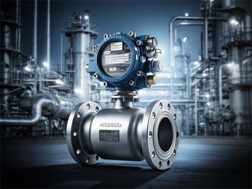
| ATEX/IECEx | European (ATEX) and international (IECEx) certification standards for electrical equipment used in potentially explosive atmospheres — required for gas flow meters in hazardous area installations. |
Questions fréquemment posées
How often should we recommend customers recalibrate their gas flow meters?
The practical answer depends on application criticality and gas service conditions, not a single universal rule. For standard plant utility gas monitoring, annual calibration verification is appropriate. For billing or custody transfer applications, semi-annual or quarterly recalibration is standard practice — and often mandated by the relevant measurement authority. Gas service with entrained liquids, variable composition, or trace contaminants warrants compressed intervals regardless of application. The data that should actually drive this decision is the meter’s calibration history: if a meter consistently shows drift of less than 0.3% per year, you can safely extend intervals; if it shows 1%+ drift annually, the root cause needs investigation rather than simply more frequent recalibration.
What’s the difference between sensor drift and calibration error?
Sensor drift is a physical change in the sensor element itself — its thermal response, its dimensional stability, its electrical resistance characteristics — that causes it to measure differently than when it was calibrated. Calibration error is the discrepancy between the meter’s reported value and the true value. Sensor drift is a root cause; calibration error is a symptom. If you recalibrate a drifted sensor without addressing the underlying drift mechanism (contamination, thermal fatigue, aging), the meter will return to out-of-specification performance within a shorter period than normal. Recalibration fixes the measurement; it doesn’t fix a degrading sensor.
Can we troubleshoot gas flow meters remotely, or do we always need to visit the site?
Remote diagnosis is viable for the majority of problem categories — and should always be the first step before committing to a site visit. A structured remote diagnostic call can confirm or rule out power supply issues, configuration errors, communication faults, and calibration status by walking the customer through their meter’s diagnostic display, output readings, and error code log. What cannot be done remotely: physical inspection of the sensor and meter bore for contamination, recalibration requiring reference standards, and weatherproofing inspection. The aim of remote diagnostics is to ensure that when a site visit does occur, the technician arrives with a clear hypothesis, the right tools, and the right parts — rather than spending the first two hours of the visit establishing basic facts that could have been gathered over the phone.
What should we do if a customer’s meter is reading significantly lower than their supplier’s measurements?
Start with reference condition verification before touching the meter. The most common cause of customer-supplier measurement discrepancy — by a significant margin — is a difference in measurement reference conditions: the customer’s meter is reporting actual volume at operating pressure and temperature, while the supplier’s station is reporting volume corrected to standard conditions. Establish which reference condition each party is using before proceeding. If reference conditions match and the discrepancy persists, proceed to calibration status verification, then temperature and pressure compensation accuracy, then installation condition review (measurement point location, upstream/downstream straight runs). Meter failure is the explanation of last resort, not first resort.
How do we know if a sensor needs replacement versus repair?
The decision framework is: can the sensor be restored to specification performance, and at what cost? If cleaning the sensor (appropriate for contamination-related drift) restores accuracy to within specification and the sensor tests within normal electrical parameters, cleaning and recalibration is the right path. If the sensor’s electrical characteristics are outside specification (resistance out of range, response time degraded, signal amplitude below threshold), recalibration cannot compensate for physical sensor degradation — replacement is required. Compare the sensor replacement cost against the ongoing cost of the measurement error: a $400 replacement sensor on a meter measuring $30,000/month of gas with a known 2% error pays back in under three weeks. Present that calculation to your customer and the decision is straightforward.
What’s the most common cause of sudden gas flow meter failures?
Blockage or obstruction — from scale, condensate, compressor oil deposits, or pipe debris — is the leading cause of sudden, unexplained flow measurement failure. Unlike sensor degradation or calibration drift, which are gradual, blockage can create a step-change in readings when a contaminant particle arrives at the sensor, or when a condensate film reaches a threshold thickness that significantly attenuates an ultrasonic signal. The practical diagnostic implication: any sudden (hours-to-days) measurement change should trigger obstruction investigation before sensor or calibration investigation.
Can temperature fluctuations alone cause significant measurement errors?
Yes — particularly in gas flow meters with fixed temperature compensation or inadequate temperature sensor performance. A 10°C temperature change in uncompensated gas measurement produces approximately 3–5% measurement error depending on the gas type and operating pressure. In natural gas distribution systems serving seasonal heating loads, ambient temperature swings of 30°C+ between summer and winter create errors exceeding 10% in inadequately compensated systems. Verify that temperature compensation is using live temperature data (not a fixed value programmed at installation), that the temperature sensor is in good calibration, and that the compensation calculation is using the correct gas properties for the actual gas composition.
How do we explain to customers why their meter needs recalibration if it still seems to be working?
Frame recalibration as accuracy maintenance — analogous to a car’s annual service, not a repair after breakdown. Quantify the cost of drift for their specific application: if their meter has drifted 1.5% high on a $40,000/month gas bill, they’ve been over-billed $600/month — $7,200/year — for measurement error that a $400 calibration service would have prevented. At that scale, the customer is paying more for the calibration error than for the calibration itself. This framing shifts the conversation from “fixing something that isn’t broken” to “protecting $7,200 per year in billing accuracy.” Most operational managers understand that framing immediately.
What’s the best way to handle a customer who insists their meter is fine despite our diagnostic findings?
Document your diagnostic findings in writing and present them objectively: “Our measurements show the meter reading 6.2% below the reference standard at midrange flow. The calibration specification for this meter is ±1%. The actual deviation is therefore 5.2% outside specification.” Numbers are harder to argue with than opinions. Offer a side-by-side comparison test against a portable reference meter as the definitive arbiter. If the customer still disputes the findings after a documented reference comparison, the appropriate response is to clearly state in writing that you recommend corrective action, document their decision to decline, and protect yourself from being held responsible for measurement accuracy on a meter they’ve declined to service.
Should we stock replacement sensors and components, or order them as needed?
Stock the components that match your most common failure modes at your highest-volume customer sites. Analyze your last two years of troubleshooting records: which sensor types failed most frequently? Which brands and models represent the majority of your installed base? Stock sufficient replacement inventory for those models to achieve same-week turnaround on the most common failures. For specialized sensors — cryogenic-rated elements, ATEX-certified assemblies, pharmaceutical-grade configurations — order lead times of 4–10 weeks are typical; maintain at least one spare on hand for any customer where that lead time would create unacceptable operational risk.
How do we handle warranty claims when troubleshooting reveals installation or configuration errors?
Communicate the finding professionally, factually, and without suggesting negligence — “Our investigation identified that the meter was installed with an upstream elbow within 3 pipe diameters of the meter inlet, against the manufacturer’s minimum 10D recommendation. This is likely contributing to the measurement deviation.” Help the customer understand what they need to do to correct the installation. Use the incident as an opportunity to establish or expand an installation support service offering — “To prevent recurrence, we offer a commissioning inspection service for new installations.” Never use an installation error finding as grounds to deny warranty coverage on a legitimate product defect; the two issues should be addressed separately.
What’s our responsibility if we troubleshoot a meter and determine it needs replacement rather than repair?
Your responsibility is to present the diagnosis honestly, quantify the options, and let the customer make an informed decision. Provide a written diagnosis: what the problem is, why repair is not viable (or is more expensive than replacement), and what the replacement options are — including any upgrade from the current specification if the application has evolved since original installation. Include a cost-benefit analysis: remaining calibrated life of the current meter (if it can be temporarily restored) versus the cost of continued measurement error versus replacement cost. Customers who receive this level of analysis trust the recommendation and act on it. Customers who are told “you need a new meter” without context do not.