Ultrasonic Natural Gas Flow Meters: A Complete Measurement and Evaluation Guide for Industry Professionals
Why This Guide Was Written for You
If you’re an OEM skid-mount manufacturer, EPC project engineer, instrument distributor, MRO maintenance lead, or utility metering engineer — this guide was built around the problems that land on your desk.
Ultrasonic natural gas flow meters are the dominant technology for fiscal and custody transfer metering in high-pressure pipelines. They’ve displaced turbine meters and orifice plates across midstream and downstream applications over the past two decades. But “ultrasonic” is not a specification — it’s a category. The performance range within that category is vast, and the gap between a correctly specified, properly installed AGA-9 certified meter and a poorly matched unit can represent millions of dollars in billing error, project rework, and regulatory exposure.
This guide covers two things in one place: what the meter actually measures (the physics and derived calculations that determine output accuracy), and how to evaluate and select the right unit (a structured framework for OEMs, EPCs, utilities, and distributors working across different applications and global markets).
No generic advice. No datasheet marketing. Only the technical specificity your procurement and engineering teams need.
📌 Note on technical terms: All specialized terms are defined on first use. A full glossary appears at the end of this guide.
What an Ultrasonic Natural Gas Flow Meter Actually Measures
Core Measurement Principle: Transit-Time Technology
An ultrasonic transit-time flow meter works by firing high-frequency acoustic pulses — typically between 100 kHz and 1 MHz — between pairs of transducers (piezoelectric crystal devices that convert electrical energy to ultrasonic sound waves and back again) mounted on the pipe wall at an angle to the flow direction.
Each transducer pair fires pulses in both directions: downstream (with the flow) and upstream (against the flow). The meter measures the time difference between these two transit times.
The relationship is straightforward:
$$\Delta t = t_{upstream} – t_{downstream}$$
When gas is flowing, a pulse traveling with the flow arrives faster than a pulse traveling against it. That time difference is directly proportional to the average gas velocity along the acoustic path.
The velocity calculation is:
$$v = \frac{L}{2 \cos\theta} \cdot \frac{\Delta t}{t_{up} \cdot t_{down}}$$
Where:
- $$L$$ = acoustic path length between transducers
- $$\theta$$ = angle of the acoustic path to the pipe axis
- $$t_{up}$$ and $$t_{down}$$ = upstream and downstream transit times
What this means practically: The meter’s native measurement is average gas velocity — not volumetric flow, not mass flow, and not energy flow. Every other output is a calculation derived from that velocity measurement combined with additional inputs.
Raw Measurement vs. Derived Values
Understanding the distinction between what the meter directly measures and what it calculates is critical for integrating ultrasonic meters into SCADA systems, DCS platforms, and flow computers.
| Output Type | Nature | Additional Inputs Required |
|---|---|---|
| Gas velocity (m/s) | Direct measurement | None — native to transit-time calculation |
| Actual volumetric flow (m³/h, ACFM) | Derived | Pipe cross-sectional area |
| Corrected/standard volumetric flow (Nm³/h, SCFM) | Derived | Actual pressure (P), actual temperature (T), gas compressibility (Z-factor) |
| Mass flow (kg/h, lb/h) | Derived | Corrected volumetric flow × gas density at standard conditions |
| Energy flow (GJ/h, MMBtu/h) | Derived | Mass flow × heating value of gas (requires gas composition) |
Industry insight: The most common integration error in new EPC projects is connecting a meter’s 4–20 mA output — which represents velocity or actual volumetric flow — to a DCS input scaled for corrected flow. The result is a reading that looks plausible but is systematically wrong by the ratio of actual to standard gas density. In a pipeline operating at 70 bar and 15°C, that ratio can exceed 70:1.
Acoustic Path Configurations: Z, V, and W
The acoustic path geometry — how the ultrasonic signal travels between transducers — determines measurement quality, especially in disturbed or asymmetric flow profiles.
Z-path (or cross-path): Transducers are mounted on opposite sides of the pipe at the same axial position, with the acoustic beam crossing the full pipe diameter in a single pass. Best suited for larger-diameter pipes (DN150 and above) where signal attenuation across the full diameter is manageable. Provides a clean, long path length and is the standard configuration for custody-transfer-grade multipath meters.
V-path (or W-path): The acoustic beam bounces off the pipe wall one or more times before reaching the receiving transducer. V-path is used on smaller pipes (DN15–DN80) where a single Z-path would be too short to provide sufficient transit-time resolution. W-path provides additional path length in very small diameters. Both configurations are more sensitive to pipe-wall coating and fouling than Z-path.
Multipath design: Multiple independent acoustic paths (typically 3, 4, 5, or 6 in custody-transfer-grade meters) sample the velocity profile at different chord positions across the pipe cross-section. The electronics use a numerical integration algorithm — essentially a weighted average of the velocity at each path height — to calculate the true mean velocity. This is what gives multipath meters their superior resistance to flow profile disturbances compared to single-path designs.
A 4-path meter with paths at heights corresponding to the Gaussian quadrature integration points achieves volumetric flow measurement uncertainty of ±0.5% of reading over a 30:1 turndown — which is why AGA Report No. 9 specifies multipath designs for custody transfer applications.
Gas Composition: The Measurement Variable Nobody Mentions
This is the most commonly underestimated source of systematic error in ultrasonic gas flow metering — and it’s invisible if you don’t know to look for it.
An ultrasonic meter cannot directly measure gas composition. But the speed of sound in the gas — which the meter uses to calculate transit times — depends directly on gas composition.
The speed of sound in an ideal gas is:
$$c = \sqrt{\frac{\gamma R T}{M}}$$
Where:
- $$\gamma$$ = heat capacity ratio (varies by gas composition)
- $$R$$ = universal gas constant
- $$T$$ = absolute temperature
- $$M$$ = molar mass of the gas mixture
For natural gas:
- Pure methane (CH₄): speed of sound ≈ 445 m/s at 15°C, 1 atm
- 10% CO₂ blend: speed of sound ≈ 418 m/s at the same conditions
- 10% hydrogen blend: speed of sound ≈ 600+ m/s at the same conditions
A meter calibrated for a 95% methane composition but operating on a gas stream with significant ethane, CO₂, or hydrogen content will produce transit-time calculations based on the wrong speed of sound. Research published in AIP Advances (2023) documents that hydrogen-mixed natural gas can lead to significantly increased errors in ultrasonic flow metering because of hydrogen’s high sound speed and low density — a combination the transit-time algorithm was not calibrated to accommodate.
Practical implication for gas composition changes greater than 5 mol% in any component: Cross-check the meter’s acoustic velocity diagnostic output against an independent calculation from a gas chromatograph (GC — an instrument that separates and quantifies individual gas components in a sample). The meter’s own speed-of-sound measurement is a powerful diagnostic: if the measured speed of sound deviates from the GC-calculated value by more than 0.2%, the meter’s calibration is being compromised by composition shift.
For OEM skid manufacturers supplying to applications where gas composition varies — biogas upgrading, LNG facilities, city gate stations receiving gas from multiple pipelines — specify meters with native GC interface capability or built-in acoustic velocity monitoring.
Pressure and Temperature: Their Role in Flow Calculation Integrity
Pressure (P) and temperature (T) do not affect the meter’s velocity measurement directly. But they critically determine the accuracy of every derived value — corrected flow, mass flow, and energy flow — through two mechanisms.
First, compressibility (Z-factor):
Real gases deviate from ideal gas behavior at elevated pressures. The compressibility factor Z (a dimensionless correction, also called the supercompressibility factor) quantifies this deviation. The AGA-8 equation of state is the industry-standard calculation method for Z in natural gas applications.
The corrected flow calculation is:
$$Q_{std} = Q_{act} \cdot \frac{P_{act}}{P_{std}} \cdot \frac{T_{std}}{T_{act}} \cdot \frac{Z_{std}}{Z_{act}}$$
A pressure transmitter reading 0.5% high on a 70 bar line produces a 0.5% error in corrected flow — before any other uncertainties are considered. On a custody transfer meter moving 100,000 Nm³/h at $10/GJ, that 0.5% error costs approximately $50,000–$80,000 per year depending on heating value.
Second, gas density:
Temperature affects gas density directly. Cold gas is denser; hot gas is less dense. A temperature transmitter reading 1°C high on a line operating at 10°C absolute temperature introduces approximately 0.34% error in corrected flow.
Best practices for P&T sensor placement:
- Install pressure taps and RTDs (Resistance Temperature Detectors — temperature sensors whose electrical resistance changes predictably with temperature) within 2D of the meter body, on the same side of any flow conditioner
- Use matched pairs: if your flow computer uses AGA-8, your pressure and temperature inputs must provide absolute values (not gauge), with uncertainty better than 0.1% for custody-transfer applications
- Specify dual-sensor redundancy on high-value fiscal meters — a single drifted PT transmitter on an uncompensated line is the most expensive and hardest-to-detect source of metering error in the field
Comprehensive Evaluation Framework for Ultrasonic Natural Gas Flow Meters
Define Your Application Requirements with Precision
Before evaluating any meter, lock down the operating envelope. Meter specifications that look identical on the datasheet can perform very differently when the application conditions are entered.
Application definition checklist:
| Parameter | What to Specify | Why It Matters |
|---|---|---|
| Operating pressure range | Min / normal / max (bar abs or psia) | Affects Z-factor, transducer design, flange rating |
| Temperature range | Min / normal / max (°C or °F) | Affects speed of sound, RTD selection |
| Gas composition | Mole fractions for all components | Determines calibration reference and acoustic velocity |
| Flow range | Min / normal / max (Nm³/h or SCFM) | Determines turndown ratio required |
| Pipe size | DN (mm) or NPS (inches) | Determines acoustic path configuration and path count |
| Application type | Custody transfer / process control / monitoring | Determines accuracy class, certification level required |
| Flow direction | Unidirectional / bidirectional | Affects meter design and flow computer configuration |
| Installation environment | Indoor / outdoor / hazardous area classification | Affects housing rating, certification, cable routing |
Accuracy class thresholds by application type:
| Solicitud | Required Accuracy | Applicable Standard |
|---|---|---|
| Fiscal custody transfer | ±0.5% of reading (at flow > 20% Qmax) | AGA Report No. 9, API MPMS Ch. 5 |
| Allocation metering | ±1.0% of reading | ISO 17089 |
| Control de procesos | ±1.0–2.0% | Application-specific |
| Consumption monitoring | ±2.0–3.0% | Utility company standard |
Evaluate Accuracy, Range, and Repeatability with Field Relevance
The ±0.5% accuracy claim on a datasheet is a starting point, not an answer. That number is typically measured at the factory, under controlled conditions, with the meter’s calibration gas composition, at 50–100% of maximum rated flow.
What to demand from vendors before committing:
Third-party flow calibration report: Not a factory certificate — a certificate from an accredited flow calibration laboratory (NIST-traceable in North America; PTB-traceable in Germany; NMI-traceable in Australia) showing actual as-measured performance across the full flow range (typically 5%, 10%, 25%, 50%, 75%, and 100% of Qmax) with measurement uncertainty stated at 95% confidence level.
Low-flow performance: Many meters that achieve ±0.5% at 50% Qmax degrade to ±1.5–2% at 5% Qmax. For applications with significant load-following variation — industrial burners, city gate stations with diurnal demand cycles — specify a minimum accuracy at 5% of Qmax and require test data.
Repeatability vs. accuracy: Repeatability (the ability to return the same reading under identical conditions) is often better than accuracy (the ability to return the correct reading). A meter with ±0.2% repeatability but ±1.5% absolute accuracy is excellent for process control but unacceptable for custody transfer. Ensure the specification covers both.
Turndown ratio: The ratio of maximum to minimum measurable flow within specification. A 30:1 turndown ratio means a meter specified at 1,000 Nm³/h maximum flow can measure accurately down to approximately 33 Nm³/h. For industrial terminals and municipal city gate stations with seasonal demand variation of 10:1 or more, specify ≥30:1 — and verify with test data, not catalog claims.
Section 8 — Analyze Installation Constraints and Site Compatibility
Insufficient upstream straight run is one of the most common and most expensive installation errors in gas metering — and no amount of calibration corrects it.
Standard straight-run requirements for natural gas applications:
| Tipo de contador | Upstream (D = pipe diameter) | Downstream |
|---|---|---|
| Single-path ultrasonic | 20D | 5D |
| 2-path ultrasonic | 15D | 5D |
| 4-path ultrasonic (standard) | 10D | 5D |
| 4-path ultrasonic + flow conditioner | 6D | 2D |
| Coriolis (reference comparison) | 0–2D | 0–2D |
Source: Cherokee Tulsa, Industrial Monitor Direct — Flow Meter Installation Guidelines
Flow conditioners — perforated plates or tube bundles inserted in the pipe upstream of the meter — reshape a disturbed velocity profile into a fully developed symmetric profile within shorter distances. For retrofit applications where achieving 10D upstream is physically impossible, a validated flow conditioner combined with a 4-path meter provides equivalent measurement uncertainty to an undisturbed 10D installation.
However: flow conditioners introduce pressure drop (the resistance to flow through the conditioner, measured in mbar or inches WC). Calculate the pressure drop penalty across the expected flow range and confirm it is acceptable for your system’s pressure balance before specifying.
For OEM skid designers: Standardize skid inlet and outlet header configurations to guarantee minimum straight-run compliance without site-specific verification for each deployment. A standardized spool piece design that satisfies AGA-9 geometry requirements at the skid boundary eliminates the most common commissioning finding.
Assess Long-Term Maintenance and Total Cost of Ownership
A correctly specified and installed ultrasonic meter with no moving parts should require minimal maintenance over a 15–20 year service life. “Minimal” doesn’t mean zero — and the maintenance items that do arise are different from those of turbine or orifice meters.
10-year TCO comparison (DN150 / 6″ pipe, natural gas, fiscal metering):
| Cost Category | Ultrasonic (4-path) | Turbine Meter | Orifice Plate (DP) |
|---|---|---|---|
| Initial purchase + installation | $18,000–$35,000 | $8,000–$15,000 | $5,000–$12,000 |
| Calibration (10-year) | $4,000–$6,000 | $8,000–$15,000 | $6,000–$10,000 |
| Parts / bearing replacement | Negligible | $3,000–$6,000 | $2,000–$4,000 |
| Pressure drop energy penalty (10y)* | $2,000–$5,000 | $4,000–$8,000 | $15,000–$25,000 |
| Unplanned downtime cost (estimate) | Bajo | Moderado | Moderado |
| Total 10-year TCO (estimate) | $24,000–$46,000 | $23,000–$44,000 | $28,000–$51,000 |
Pressure drop energy cost calculated at $0.05/kWh, 8,000 operating hours/year
The ultrasonic meter’s upfront cost premium is typically recovered within 5–7 years through reduced maintenance, lower pressure drop (which directly reduces compression energy cost in gas pipelines), and extended calibration intervals enabled by onboard diagnostics.
Diagnostic outputs to require: A quality ultrasonic meter provides continuous self-diagnostic data including: signal strength (gain) on each transducer pair, acoustic signal-to-noise ratio, individual path velocity values vs. integrated mean velocity, speed of sound measurement vs. AGA-8 calculation, and electronics health status. These outputs allow early detection of fouling, transducer degradation, and flow profile disturbances — before they affect measurement accuracy.
Verify Compliance with Regional and Industry Standards
Selecting a meter that doesn’t satisfy the applicable regulatory or contractual standard for your project is not a specification shortcut — it’s a project liability. Getting the compliance requirements right before vendor evaluation is faster and cheaper than correcting them after purchase order.
Applicable standards by application:
| Estándar | Organization | Solicitud |
|---|---|---|
| AGA Report No. 9 | American Gas Association | Multipath ultrasonic meters for natural gas fiscal metering |
| API MPMS Chapter 5.8 | American Petroleum Institute | Ultrasonic flow measurement — general requirements |
| ISO 17089-1 | International Organization for Standardization | Measurement of fluid flow — ultrasonic meters for gas |
| OIML R 137 | International Organization of Legal Metrology | Gas meters — requirements and test methods |
| EN 12405 / EN 1359 | European Committee for Standardization | Flow computers, gas meters — European utility compliance |
| ASME MFC-5M | American Society of Mechanical Engineers | Ultrasonic flow measurement in closed conduits |
| IEC 60079 / ATEX Directive | International Electrotechnical Commission / EU | Hazardous area (Ex) equipment certification |
| IECEx | IEC Conformity Assessment System | Global Ex certification for hazardous area equipment |
AGA-9 compliant vs. AGA-9 certified — a distinction that matters:
AGA-9 compliant means the manufacturer states the meter’s design meets the performance requirements of the standard. There is no third-party validation required to make this claim.
AGA-9 certified means an independent, accredited test facility has actually tested the specific meter model against the standard’s requirements, and the performance test results are documented in a report that can be audited. For custody transfer applications where the measurement is used in commercial transactions, certification — not just compliance — is what gas pipeline operators, regulators, and contract counterparties accept.
For hazardous area applications: Natural gas metering stations are classified as Zone 1 or Zone 2 (ATEX/IECEx) or Class I Division 1 or Division 2 (NEC in North America). Meters must carry certification for the specific zone/division of the installation. Confirm the certification covers the complete meter assembly — housing, transducers, terminal compartment, and cable gland — not just the electronics module.
Conduct Rigorous Vendor Qualification and Technical Due Diligence
The vendor you choose for a high-value metering application is as important as the specification. Three questions reveal more than any datasheet:
1. Can you provide reference sites for this specific application type — same pressure class, pipe size, gas composition profile, and flow range — with contact names?
A vendor with genuine experience in LNG regasification terminal metering, for example, will have multiple reference sites they can name, and those sites will have metering engineers who will take your call. A vendor who hesitates or provides only general references is telling you something about the depth of their application experience.
2. What is your firmware update policy, and how do you manage backward compatibility?
Ultrasonic meters deployed for 15–20 years will undergo multiple firmware updates over their operational life. Updates that change K-factor calculation methods, AGA-8 equation version, or path integration algorithms can alter the meter’s reported flow without triggering any alarm. Require a documented firmware change management process that includes: change log, backward-compatibility statement, performance validation testing, and calibration re-verification requirements.
3. What is your cybersecurity posture for connected meter platforms?
As Modbus TCP, HART IP, and cloud-connected metering platforms become standard, smart ultrasonic meters become network endpoints. ARC Advisory Group has documented specific cybersecurity threats to smart flowmeters including firmware manipulation, data injection, and denial-of-service attacks on metering systems. Require IEC 62443 compliance documentation covering the specific security level (SL-1 to SL-4) applicable to your installation’s security zone designation.
Integrate Digital Capabilities and Future-Proofing Features
The intelligence of a modern ultrasonic flow meter is only as useful as the integration infrastructure around it — protocol compatibility, cybersecurity, and SCADA architecture determine whether diagnostic data becomes operational value or unused noise.
Communication protocol compatibility matrix:
| Protocolo | Best Suited For | Key Consideration |
|---|---|---|
| 4–20 mA analog | Simple DCS/PLC inputs | Limited to flow rate only; no diagnostics |
| Pulse output | Totalized flow to flow computers | Verify pulse weight matches flow computer configuration |
| HART (4–20 mA + digital) | Field device management, basic diagnostics | HART 7 enables more diagnostic parameters than HART 5 |
| Modbus RTU / TCP | SCADA integration, multi-register data | Confirm register map is documented; verify byte order |
| PROFIBUS PA | Process automation DCS integration | Dominant in petrochemical sector; requires PA segment coupler |
| Foundation Fieldbus H1 | Integrated process automation | Complex commissioning; powerful for multi-loop control |
| OPC UA | Plant-level data integration, IIoT | Emerging as preferred for digital twin and predictive maintenance |
| MQTT | Edge-to-cloud data transport | Lightweight; requires broker; growing in IIoT applications |
For most EPC and utility applications in 2026, specifying HART 7 as the primary communication protocol with Modbus TCP as secondary covers the widest range of DCS, SCADA, and flow computer compatibility without requiring protocol gateway hardware.
Hydrogen and RNG readiness:
The transition toward renewable natural gas (RNG — biomethane upgraded from biogas to natural gas network quality) and hydrogen blending into natural gas pipelines is creating new measurement challenges that existing meter populations were not designed for.
Hydrogen’s speed of sound in gas is approximately 1,270 m/s at standard conditions — nearly three times that of methane (445 m/s). A blend of 20% hydrogen by volume shifts the mixture speed of sound by approximately 70–80 m/s. Research published in AIP Advances confirmed that this shift introduces significant measurement errors in ultrasonic meters calibrated for pure natural gas, particularly at the lower end of the flow range where velocity resolution is most sensitive to speed-of-sound accuracy.
Firmware-upgradable platforms that allow re-characterization of the AGA-8 / AGA-10 calculation to accommodate hydrogen-methane mixtures — without hardware replacement — provide 15-year protection against this specification risk. Confirm this capability with your vendor before procurement finalization on any project where pipeline hydrogen injection is a regulatory possibility.
Optimize Procurement and Supply Chain Reliability
A correctly specified meter that cannot be delivered on time, supported locally, or replaced within a reasonable lead time is a project risk — not a procurement success.
Supply chain evaluation factors:
| Factor | What to Verify | Minimum Acceptable Standard |
|---|---|---|
| Standard lead time | Catalog model, standard configuration | 8–16 weeks for standard sizes |
| Custom/configured lead time | Non-standard pressure class, special certifications | 16–26 weeks maximum |
| Spare parts availability | Transducer pairs, electronics module, seals | 5-year parts availability guarantee |
| Local service network | Calibration facilities, field service engineers | Service center within 500 km for critical installations |
| Calibration traceability | NIST, PTB, NMI or equivalent national standard | Full traceability document included with every unit |
| Replacement transducer compatibility | Backward-compatible across multiple model generations | Critical for 15-20 year lifecycle |
For EPC contractors managing multi-unit projects with 20–100 identical meters across a pipeline, negotiate volume pricing with the following contractual protections: locked pricing for additional units ordered within 24 months; guaranteed backward-compatibility of replacement transducers; and a documented obsolescence plan if the specific model is discontinued.
Jade Ant Instruments supports OEM and EPC volume procurement for ultrasonic gas flow measurement applications, with application engineering review before order confirmation to verify that specifications match actual site conditions — the single most effective intervention for preventing field rework.
The Final Selection Scorecard: A Data-Driven Decision Framework
Reduce subjective procurement decisions by applying a weighted scoring matrix to shortlisted vendors. The following weighting is calibrated for custody transfer and high-value fiscal metering applications; adjust weights for monitoring-only applications by reducing the compliance weight and increasing the TCO weight.
Vendor Evaluation Scorecard (custody transfer / fiscal metering):
| Criterio de evaluación | Weight | Scoring Basis (1–10) |
|---|---|---|
| Measurement accuracy (calibration data vs. required specification) | 25% | 10 = Third-party certified ±0.3% across full range |
| Compliance & certification (AGA-9, ATEX/IECEx, OIML, regional approval) | 20% | 10 = All required certifications with full documentation |
| Total Cost of Ownership (15-year lifecycle, P&T drop, maintenance schedule) | 15% | 10 = Lowest lifecycle cost with documented assumptions |
| Technical support & service network (response time, local presence) | 15% | 10 = On-site service within 48 hours, 24/7 remote support |
| Integration capability (protocol support, SCADA compatibility, cybersecurity) | 15% | 10 = Native support for all required protocols + IEC 62443 documentation |
| Future-proofing (firmware upgrade path, hydrogen compatibility, IIoT readiness) | 10% | 10 = Documented upgrade path for H₂ blends + OPC UA support |
| TOTAL | 100% | Maximum score: 10.0 |
How to use this scorecard in practice:
- Define minimum threshold scores for mandatory criteria: accuracy and compliance should both require a minimum score of 7/10 (effectively equivalent to ≥70% of maximum performance) to qualify for further evaluation.
- Require each vendor to provide documented evidence for each criterion — not self-reported scores.
- Have your evaluation team score independently before comparing, to prevent anchoring bias.
- For applications above $200,000 contract value, include a physical pilot test: install a candidate meter alongside your current reference meter in a spool piece for 30–90 days of parallel operation before making the final selection.
Contractual safeguards to include in the purchase order:
- Performance warranty: meter must achieve certified accuracy specification in the field installation, with remediation at vendor’s cost if not achieved within 90 days of commissioning
- Service Level Agreement: maximum on-site response time for critical faults (typically 24–48 hours)
- Software/firmware IP protection: all configuration software, firmware, and diagnostic algorithms remain accessible to the end user regardless of changes in vendor ownership or product status
- Cybersecurity clause: vendor must notify the user within 72 hours of any security vulnerability discovered in connected product firmware
🎬 Video: How Ultrasonic Transit-Time Flow Meters Work
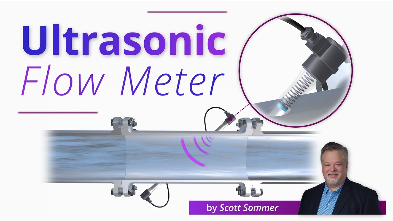
This video explains the physics of transit-time measurement, how acoustic paths generate velocity data, and how multipath designs achieve fiscal-grade accuracy — essential background for engineers specifying or commissioning ultrasonic gas meters for the first time.
Industry-Specific Applications and Compliance Requirements
Upstream: Wellhead Testing and Flare Gas Recovery
Wellhead metering demands wide operating temperature ranges (−40°C to +120°C in some regions), explosion-proof housing, and tolerance of variable gas composition as reservoir gas characteristics change over the field production life.
For flare gas recovery metering — measuring gas that was previously flared and is now being captured for processing or fuel — the gas composition is often highly variable and may contain significant quantities of H₂S, CO₂, and heavier hydrocarbons. Specify thermal range, gas composition range, and materials compatibility (H₂S service requires NACE MR0175-compliant wetted materials) explicitly in the purchase specification.
Midstream: Compressor Stations and Pipeline Custody Transfer
The most demanding application environment for ultrasonic meters. Custody transfer metering at compressor stations handles high pressures (up to 150 bar), high flow rates, and the commercial stakes of bilateral gas trading contracts.
AGA Report No. 9 governs the design, installation, and operation of multipath ultrasonic meters in this application. Key requirements include: minimum 4-path design; flow calibration with uncertainty < ±0.2% at the accredited laboratory; installed meter verification using a gas prover or master meter at defined intervals; and full diagnostic data logging accessible for regulatory audit.
Downstream: City Gate Stations, LNG, and Industrial Fuel Gas
City gate stations — where transmission pipeline gas is pressure-reduced and metered into local distribution networks — experience wide diurnal flow variation (10:1 or more between nighttime minimum and peak morning demand). This is where turndown ratio specification is most critical: a meter undersized for peak flow clips the measurement; a meter oversized for minimum flow loses accuracy.
For LNG facilities, meters must handle cryogenic temperatures during boil-off gas measurement and rapidly varying gas compositions during loading/unloading operations.
For industrial fuel gas metering at boilers, furnaces, and combined heat and power (CHP) units, the key requirement is reliable measurement at low differential pressures, with alarm output for fuel-to-air ratio management.
Technical Resources from Jade Ant Instruments
El ultrasonic flow meter industrial applications guide at Jade Ant Instruments covers the eight most common industrial deployment scenarios with application-specific selection notes. For distributors building their client advisory capability, the ultrasonic vs. traditional flow meters comparison guide provides a structured framework for communicating the TCO advantages to clients who are comparing technologies rather than just requesting a quote.
El smart ultrasonic flow meter guide covers the wireless, touchscreen, and remote diagnostic capabilities of next-generation platforms — directly relevant for utility operators and EPC teams building digital metering infrastructure.
Glossary of Key Technical Terms
| Term | Plain-Language Definition |
|---|---|
| AGA-8 | American Gas Association calculation method for natural gas compressibility factor (Z-factor) used in converting actual to corrected flow |
| AGA-9 | American Gas Association Report No. 9 — the industry standard governing multipath ultrasonic meters for natural gas custody transfer |
| ACFM | Actual Cubic Feet per Minute — gas volume at operating temperature and pressure, not corrected to a reference condition |
| ATEX | European Union directive (ATmosphères EXplosibles) governing equipment for use in potentially explosive atmospheres |
| Calibration traceability | The documented chain of comparisons linking a meter’s calibration to a national or international measurement standard |
| DCS | Distributed Control System — a plant-level control system that monitors and manages process instruments across an industrial facility |
| Ex certification | Certification confirming equipment is safe for use in hazardous (explosive atmosphere) areas — issued under IECEx or ATEX frameworks |
| Flow conditioner | A device (perforated plate or tube bundle) installed upstream of a flow meter to produce a symmetric, fully developed velocity profile in shorter pipe runs |
| GC (Gas Chromatograph) | An analytical instrument that separates and quantifies individual components in a gas sample — used to determine gas composition |
| HART 7 | Highway Addressable Remote Transducer version 7 — a field device communication protocol overlaying digital data on a 4–20 mA analog signal |
| IECEx | International Electrotechnical Commission system for Ex equipment certification — provides global recognition of hazardous area approvals |
| Multipath | An ultrasonic meter design using three or more independent acoustic paths to measure velocity at different heights across the pipe cross-section |
| NIST | National Institute of Standards and Technology (USA) — the national metrology body whose measurement standards underpin calibration traceability |
| Nm³/h | Normal cubic meters per hour — gas volume corrected to standard conditions of 0°C and 1 atmosphere absolute |
| OPC UA | OPC Unified Architecture — an industrial communication standard designed for secure, reliable data exchange between machines and cloud systems |
| Piezoelectric transducer | A device that converts electrical energy to ultrasonic sound waves and vice versa — the sensing element in an ultrasonic flow meter |
| RTD | Resistance Temperature Detector — a precision temperature sensor used for flow compensation in gas metering |
| SCFM | Standard Cubic Feet per Minute — gas volume corrected to US standard conditions of 60°F and 14.696 psia |
| Speed of sound | The velocity at which acoustic energy travels through a medium — depends on gas composition, temperature, and pressure, and is the foundation of transit-time measurement |
| TCO | Total Cost of Ownership — the complete financial cost of acquiring, installing, operating, and maintaining an asset over its full service life |
| Transit time | The time taken for an ultrasonic pulse to travel from one transducer to another — the primary measurement from which gas velocity is calculated |
| Turndown ratio | The ratio of maximum to minimum measurable flow within a meter’s specified accuracy — higher ratios indicate greater measurement range |
| Z-factor | Compressibility factor — a dimensionless correction that accounts for the deviation of real gas behavior from ideal gas behavior at elevated pressures |
Preguntas frecuentes
1. What is the difference between AGA-9 compliant and AGA-9 certified ultrasonic meters?
AGA-9 compliant is a manufacturer’s self-declaration that the meter’s design meets the performance requirements of AGA Report No. 9. No independent testing is required to make this claim. AGA-9 certified means an accredited flow calibration laboratory has tested the specific meter model against the standard’s accuracy and functional requirements, producing a test report that can be reviewed by gas pipeline operators, regulators, and contract counterparties. For custody transfer applications — where meter readings underpin commercial gas transactions — only certified meters are accepted by most pipeline operators and regulatory bodies.
2. Can ultrasonic meters handle wet gas or entrained liquids in distribution lines?
An ultrasonic meter will continue to produce readings in wet gas conditions, but accuracy degrades as liquid loading increases. Research published in gas measurement conference proceedings documents that multipath meters can detect the presence of liquid mist through changes in signal strength and path velocity imbalance — but the measurement uncertainty increases significantly with liquid content above 0.05% by volume. For applications where liquid dropout is possible, specify meters with advanced path diagnostics that can detect and alarm on liquid presence, and install a gas filter or separator upstream of the meter body.
3. What is the minimum straight-run piping required for accuracy?
For a 4-path ultrasonic meter without a flow conditioner in natural gas service, the AGA-9 recommendation is 10 pipe diameters (10D) of straight, unobstructed pipe upstream of the meter inlet and 5D downstream. With a validated flow conditioner, this can be reduced to 6D upstream and 2D downstream for many meter models — with the meter’s factory calibration performed under the same conditioned flow conditions. Single-path meters require 20D upstream in disturbed conditions. Always confirm the specific straight-run requirement in the manufacturer’s installation documentation for your exact configuration.
4. How often does an ultrasonic meter need recalibration in field service?
For custody transfer applications, AGA-9 recommends annual or biennial in-situ verification using a transfer prover or master meter, with laboratory recalibration triggered only if drift is detected. For process control or monitoring applications, most meters with stable diagnostic indicators can operate 3–5 years between laboratory calibrations. The shift in industry practice is toward condition-based calibration — scheduling recalibration based on diagnostic data showing actual drift, rather than fixed time intervals — which reduces unnecessary calibration cost while maintaining measurement integrity.
5. Why does my meter show drift when gas composition changes?
The speed of sound in gas changes with composition. An ultrasonic meter calibrated for 95% methane will produce systematic flow measurement error when operating on a gas stream with elevated ethane, CO₂, or hydrogen content, because the transit-time calculation assumes a different acoustic velocity than the gas actually exhibits. The diagnostic indicator is a discrepancy between the meter’s measured speed of sound and the speed of sound calculated independently from a gas chromatograph analysis. Correct this by updating the gas composition input to the flow computer, or by recalibrating the meter at the new reference composition.
6. Can I use one ultrasonic meter for both natural gas and hydrogen-blended streams?
Not without verification and potentially recalibration. Hydrogen’s speed of sound is approximately 1,270 m/s at standard conditions — nearly three times that of methane. Even a 10% hydrogen blend shifts the mixture acoustic velocity by enough to introduce measurement errors of 1–3% in meters calibrated for pure natural gas. Before accepting a hydrogen-blended gas stream on an existing ultrasonic meter, confirm with the manufacturer that the meter’s firmware can accommodate AGA-8 calculations for hydrogen-containing mixtures, and request factory recalibration on the representative gas blend.
7. What input parameters are critical for correct flow calculation?
Three inputs are essential for corrected volumetric flow: actual pressure (absolute, not gauge), actual temperature (absolute, in Kelvin or Rankine), and gas composition (mole fractions for the calculation of Z-factor via AGA-8). For energy flow, a fourth input is required: the heating value of the gas, typically provided by an online gas chromatograph or from a pipeline quality certificate updated at defined intervals. Errors in any of these inputs translate directly to proportional errors in the derived flow values.
8. How do pressure and temperature transmitters affect overall metering accuracy?
They are part of the measurement uncertainty budget. For a custody transfer meter targeting ±0.5% combined measurement uncertainty, the allowed contributions from pressure and temperature transmitters are typically ±0.1% each — which means specifying transmitters with ±0.05% or better accuracy, properly located within 2 pipe diameters of the meter body. Transmitter calibration must be maintained at the same frequency as the flow meter itself — a freshly calibrated flow meter combined with a drifted pressure transmitter still produces inaccurate corrected flow.
9. Is AGA-9 compliance mandatory for all custody transfer applications?
In the United States, AGA-9 is the dominant industry standard for natural gas custody transfer metering and is referenced in most pipeline purchase agreements and state utility commission regulations. Internationally, ISO 17089 and OIML R 137 serve equivalent functions. Not all jurisdictions legislatively mandate a specific standard, but gas purchase contracts between counterparties almost universally specify one as the governing document for measurement accuracy and verification requirements. Check the specific contractual and regulatory requirements for each project jurisdiction before specifying.
10. What diagnostic tools are available to verify meter health without removing it from service?
Modern 4-path custody-transfer-grade ultrasonic meters provide continuous real-time diagnostics including: individual path transit times and velocities; signal gain (amplitude) on each transducer pair; speed of sound in the gas vs. AGA-8 calculated value; flow symmetry index (ratio of upstream and downstream path velocities, indicating profile disturbance); and electronics temperature and power supply health. Zero verification (confirming the meter reads zero at confirmed zero-flow conditions during a process shutdown) provides the most complete in-situ calibration check. Some advanced platforms support remote proving via master meter bypass without requiring meter removal.
11. How do I integrate ultrasonic flow data into my existing DCS or SCADA system?
Begin with protocol verification: confirm which communication interface your DCS supports natively (HART, Modbus RTU, Modbus TCP, PROFIBUS PA, Foundation Fieldbus, or 4–20 mA analog). Obtain the meter’s register map or device description (DD) file from the manufacturer and verify it loads correctly in your asset management tool before commissioning. Map each critical parameter — flow rate, totalized volume, speed of sound, signal quality, and diagnostic alarms — to dedicated SCADA tags before field installation to prevent late-stage integration rework.
12. What are the differences between multipath and single-path meters?
A single-path meter uses one acoustic path at a fixed chord position across the pipe. Its measurement accuracy depends on the assumption that the velocity at that single chord position accurately represents the mean velocity across the full cross-section — an assumption that fails in disturbed flow profiles caused by upstream bends, valves, or compressors. A multipath meter uses 3–6 independent paths at different heights across the pipe and applies a numerical integration algorithm to calculate the true mean velocity with explicit profile compensation. The measurement uncertainty improvement from single-path to 4-path can be 3–5× under disturbed conditions, which is why AGA-9 specifies multipath meters for custody transfer.
13. Can ultrasonic meters be used for bidirectional flow in pipeline reversals?
Yes — bidirectional flow capability is a native feature of transit-time ultrasonic meters, because the physics of the measurement is symmetric: the upstream–downstream time difference simply reverses sign when flow direction reverses. Confirm that the specific meter model and flow computer are configured to handle bidirectional totalization and to report both forward and reverse volume accumulation. Some meters require explicit bidirectional mode activation in firmware; others handle it automatically.
14. What causes signal loss in ultrasonic meters, and how can it be prevented?
Signal loss occurs when the acoustic amplitude received by a transducer falls below the minimum threshold for reliable transit-time measurement. Common causes include: transducer face fouling from pipe scale, condensate, or wax deposition; pipe internal coating or lining that attenuates the acoustic signal; gas composition changes that increase acoustic absorption (notably CO₂-rich streams); and transducer element degradation after 15–20 years of service. Prevention: specify meters with continuous gain monitoring that generates an early alarm when signal strength drops to 70% of baseline (before it reaches the measurement failure threshold), and implement a scheduled transducer cleaning protocol aligned with planned maintenance windows.
15. How do I size the right ultrasonic meter for high-pressure transmission lines?
Meter sizing for high-pressure gas involves three inputs: maximum volumetric flow rate at actual (operating) conditions (Qact), minimum volumetric flow rate (to verify turndown ratio), and operating pressure and temperature (to convert between standard and actual conditions). The key relationship is:
$$Q_{act} = Q_{std} \cdot \frac{P_{std}}{P_{act}} \cdot \frac{T_{act}}{T_{std}} \cdot \frac{Z_{act}}{Z_{std}}$$
At 70 bar operating pressure and 15°C, a gas stream of 100,000 Nm³/h at standard conditions flows at approximately 1,400 Nm³/h at actual conditions — a 70:1 ratio. The meter body is sized for the actual volumetric flow, not the standard flow. Use the manufacturer’s sizing tool with actual P, T, and Z-factor inputs to select the appropriate meter diameter and confirm it achieves ±0.5% accuracy at both maximum and minimum actual volumetric flow.
16. Are there cost advantages over turbine or Coriolis meters in large-diameter lines?
For pipe sizes above DN200 (8″), ultrasonic meters typically offer a significant cost advantage over Coriolis meters (which become impractical at large diameters due to size and pressure drop) and a lifecycle advantage over turbine meters (whose bearing wear and pressure drop costs compound over a 15–20 year service life). The pressure drop advantage is particularly significant in high-flow transmission applications: an ultrasonic meter produces essentially zero permanent pressure loss, while a turbine meter at full flow produces 50–200 mbar. At transmission volumes of 500,000 Nm³/h and compression costs of $0.05/kWh, eliminating 100 mbar of pressure drop saves approximately $180,000–$220,000 per year in compression energy.
17. What certifications are needed for use in hazardous (Class I Div 1) areas?
For North American installations: UL or FM certification for Class I, Division 1, Group D (natural gas) or Group C (propane, butane) as applicable. For European and global installations: ATEX certification for Zone 1, Gas Group IIA (propane) or IIB (ethylene, hydrogen blends), with the appropriate temperature class (T3 or T4 for most natural gas applications). IECEx certification provides international mutual recognition of the ATEX test results in over 50 countries. Confirm that the full meter assembly — housing, transducers, junction boxes, and cables — carries the correct certification level, not just the electronics module.
18. How does fouling or coating inside the pipe affect measurement accuracy?
Internal fouling affects ultrasonic measurement through two mechanisms: a reduction of the pipe’s effective cross-sectional area (which the meter’s calculation assumes is fixed at the calibrated value), and an alteration of the acoustic path length and reflection geometry if the fouling builds up on the transducer faces. Research from ASGMT gas measurement conferences documents that a 1 mm coating on a 150 mm pipe reduces the effective area by approximately 2.6%, causing a proportional overstatement of volumetric flow. Monitor the meter’s speed of sound diagnostic: a stable speed of sound with increasing gain (the electronics are compensating for reduced acoustic signal amplitude) is a classic early indicator of transducer face or pipe-wall fouling.
19. Can ultrasonic meters operate reliably in low-flow or turndown-intensive applications?
This is where meter selection matters most. A 4-path custody transfer meter in a DN150 pipe rated for 5,000 Nm³/h maximum will typically maintain ±0.5% accuracy down to approximately 250 Nm³/h (20:1 turndown). Below that threshold, velocity resolution becomes insufficient for fiscal-grade measurement. For city gate stations or industrial burner applications requiring accurate measurement at 3–5% of maximum rated flow, specify a meter with ≥30:1 turndown ratio and verify with independent test data at the low-flow condition — the datasheet claim is your starting point, not your endpoint.
20. What support do manufacturers provide for configuration and commissioning?
This varies enormously and is worth investigating before vendor shortlisting. Premium manufacturers provide: factory acceptance testing (FAT) witnessed by the customer; remote configuration tools accessible via laptop or tablet during commissioning; application engineer availability by phone during startup; and documented first-run configuration templates for standard applications. For EPC projects with 30+ meter installations, negotiating a pre-commissioning support visit from the manufacturer’s application team — to verify configuration files, verify communication integration, and train the client’s operations team — typically costs $3,000–$8,000 and prevents delays worth 10–30× that amount.
External references used in this guide:
- Merobix — What Is AGA-9? Ultrasonic Metering Standard
- Fuji Electric — How Multipath Ultrasonic Flowmeters Improve Accuracy in Large Pipelines
- Industrial Monitor Direct — TransFlection vs Transit-Time for Custody Transfer
- Cherokee Tulsa — Flow Conditioning for Flow Meter Accuracy
- Kobold USA — International Standards for Hazardous Area Instrumentation
- ARC Advisory Group — Cybersecurity Threats to Smart Flowmeters
- Mustang Sampling — Measurement and Analysis in the Evolving RNG Market
- Jade Ant Instruments — Top 8 Ultrasonic Flow Meter Industrial Applications
- Jade Ant Instruments — Ultrasonic vs. Magnetic vs. Turbine Flow Meter Guide
- Jade Ant Instruments — Smart Ultrasonic Flow Meter for Field Operations
- Jade Ant Instruments — Ultrasonic Flow Meter Buying Guide for Distributors