
Selecting the wrong flow meter for a gas-critical process does not just affect measurement accuracy — it can derail an entire production batch. A semiconductor fab running chemical vapor deposition (CVD) with a conventional rotameter calibrated only for nitrogen will drift by several percent when switching to silane, silently skewing film thickness and triggering costly rejects downstream. Conversely, specifying a premium Thermal Mass Flow Controller (TMC) for a simple compressed-air monitoring loop wastes capital that could fund three additional control loops elsewhere.
This guide exists to close that gap. We compare Thermal Mass Flow Controllers — precision instruments that measure and regulate gas flow at the molecular (mass) level — against the four most widely deployed conventional flow meter technologies: differential pressure (DP/orifice), turbine, variable-area (rotameter), and gravimetric meters. We cover operating principles, real-world performance data, total cost of ownership, and a structured decision framework so your team can make a defensible specification choice, not an educated guess.
The analysis is relevant to process engineers, instrumentation designers, and procurement specialists working in semiconductor fabrication, pharmaceuticals, chemical processing, food and beverage, and general industrial applications.
📖 Key Terminology — Defined on First Use
What Is a Thermal Mass Flow Controller (TMC)?
Definition and Core Function
A Thermal Mass Flow Controller is a closed-loop instrument that simultaneously medidas y regulates the mass flow rate of a gas stream. The “thermal” in its name describes its sensing physics: heat transfer between a heated element and the flowing gas is directly proportional to the gas’s mass flow rate, heat capacity (Cₚ), and density.
Unlike a simple flow meter that only reports what is happening, a TMC acts: it reads the current flow, compares it to the commanded setpoint, and adjusts an internal proportional control valve (typically a solenoid or piezoelectric valve) to close the loop — all within a single housing. This integrated control loop is what differentiates a controller (TMC) from a meter (TMM, Thermal Mass Flow Meter).
The output is expressed in sccm, slm, or g/h — mass-referenced units that do not change with process temperature or pressure fluctuations. This is the TMC’s single biggest operational advantage over volumetric technologies.
Typical Applications
TMCs dominate wherever precise gas composition, purity, and dosing control matter at the molecular level. The global TMC market reached approximately $1.6 billion in 2025 and is projected to grow at a 6.0% CAGR through 2030, driven almost entirely by semiconductor fab expansion and pharmaceutical bioprocess growth.
- Semiconductor fabrication: CVD, ALD (Atomic Layer Deposition), plasma etch, and ion implantation all require gas ratios controlled to sub-percent levels. A 1% silane flow error in PECVD translates directly into film thickness non-uniformity across a wafer, failing electrical specifications. Leading fabs run 50–200 TMCs per deposition chamber cluster.
- Pharmaceutical & bioprocess: Bioreactor sparging with precise O₂/CO₂/N₂ ratios controls cell culture pH and dissolved oxygen. A major European biopharma running a 2,000-L fed-batch reactor reported that switching from rotameters to TMCs reduced batch-to-batch dissolved oxygen variance by 34%, directly improving yield consistency.
- Chemical processing & R&D: Catalyst testing rigs, hydrogenation reactors, and gas blending panels use TMCs for recipe reproducibility across campaigns.
- Food & beverage: Modified Atmosphere Packaging (MAP) lines require N₂/CO₂ blending within ±2% to maintain shelf life compliance.
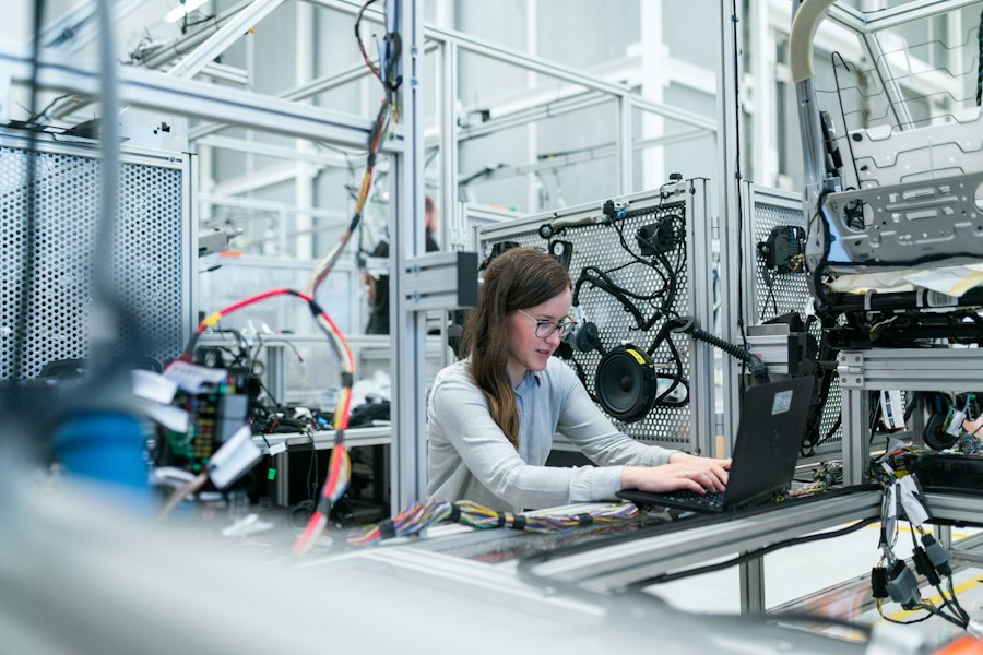
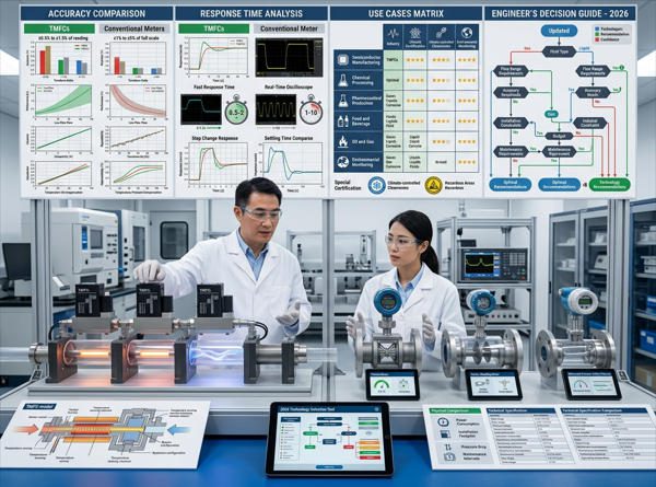
Figure 1 — Process engineers in precision manufacturing environments rely on thermal mass flow controllers for gas dosing accuracy that conventional meters cannot achieve.
How Thermal Mass Flow Controllers Work
Operating Principle: Thermal Sensing and Mass Flow Regulation
The core sensing element of a bypass-type TMC consists of a narrow capillary tube — typically 316 stainless steel — wound with two resistive temperature detector (RTD) coils (upstream heater/sensor and downstream sensor). A constant current heats the midpoint of the capillary while gas flows through it.
When no gas flows, both RTDs read the same temperature — symmetric heat distribution. When gas flows, it carries thermal energy downstream: the upstream sensor cools slightly, the downstream sensor warms. The ΔT signal is directly proportional to the mass flow rate — no temperature or pressure correction needed, because both properties are already encoded in the heat transfer equation.
The TMC’s internal PID controller reads this ΔT-derived flow signal, compares it to the digital setpoint command (via RS-485, PROFIBUS, or 0–5 V analog), and modulates the control valve accordingly. The entire sense-compare-correct cycle occurs in under 200 milliseconds on modern digital TMCs.
Direct-Sensing vs. Bypass Design: Traditional bypass TMCs route a fraction of the total gas flow through the capillary sensor tube, with the rest flowing through a laminar-flow bypass element. Direct-sensing (MEMS-based) TMCs measure the full flow directly using a micro-fabricated chip sensor — enabling faster response, lower dead volume, and broader gas compatibility, but at higher unit cost. For semiconductor etch processes requiring gas switching in <100 ms, direct-sensing architectures have largely replaced bypass designs since 2020.
▶ Video: Thermal Mass Flow Meter/Controller — Principle of Operation | Bronkhorst. Demonstrates the capillary bypass sensing principle, ΔT measurement, and control valve operation in real instrumentation.
Key Performance Parameters
| Parámetro | Typical TMC Specification | High-End TMC Specification | Notes / Context |
|---|---|---|---|
| Precisión | ±1.0% FS | ±0.5% Rd + 0.1% FS | %Rd specs are tighter at low flow than %FS |
| Repetibilidad | ±0.2% FS | ±0.1% Rd | Critical for process recipe reproducibility |
| Relación de reducción | 50:1 | 100:1 to 200:1 | Alicat MEMS devices reach 10,000:1 |
| Response Time (setpoint) | <1 s (analog) | <200 ms (digital) | Direct-sensing designs <100 ms |
| Warm-Up Time | 5–30 min (thermal) | <1 s (MEMS/DP-based) | Key disadvantage vs. DP-based alternatives |
| Caída de presión | Low (0.1–2 bar typical) | Very Low (<0.5 bar) | Lower than orifice plates at equivalent flow |
| Output Signals | 0–5 V, 4–20 mA | RS-485, PROFIBUS, EtherNet/IP, HART | Digital comms enable remote diagnostics |
| Gas Compatibility | Clean dry gases with known Cₚ | Same + corrosive gases (special wetted materials) | Requires conversion factor for non-N₂ gases |
| Particle Tolerance | Low — upstream filter required | Low — upstream filter required | Capillary tubes clog with particulates |
Sources: Bronkhorst EL-FLOW specifications; Metlan Instrument TMC technical guide; Alicat Scientific turndown documentation.
Conventional Flow Meters: An Overview
Common Types and Their Measurement Principles
“Conventional flow meters” is not a single technology — it is a family of instruments that share a common limitation: they primarily measure volumetric flow, not mass flow. Converting volumetric flow to mass flow requires knowledge of gas density, which changes with temperature and pressure. This indirect path to mass flow measurement is where most conventional meters introduce error.

Figure 2 — Conventional flow measurement technologies span a wide cost and complexity range. Rotameters cost as little as $50; Coriolis meters can exceed $15,000. Matching technology to application requirements avoids both over-specification and costly misapplication.
Type-by-Type Breakdown
| Tipo de contador | Principio de medición | Accuracy (Typical) | Servicio de preparación de la cama | Moving Parts? | Primary Limitation |
|---|---|---|---|---|---|
| Rotameter (Variable Area) | Float rises in tapered tube proportional to volumetric flow | ±2–5% FS | 10:1 | Yes (float) | Gas-specific calibration; manual reading; no digital output |
| Differential Pressure (Orifice Plate) | Measures ΔP across fixed restriction; flow ∝ √ΔP | ±0.75–2.0% AR | 3:1 | No | Very limited turndown; requires T/P compensation; high permanent pressure loss |
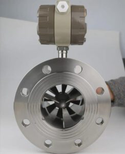
| Turbine Flow Meter | Rotor spins at angular velocity proportional to volumetric flow | ±0.5–1.0% Rd | 20:1 | Yes (rotor + bearings) | Moving parts wear; clean gas only; no inherent mass flow output |
| Vortex Shedding | Vortices shed from bluff body; frequency ∝ velocity | ±0.5–1.5% Rd | 10:1 | Minimal (sensor) | Minimum velocity threshold; vibration sensitivity; T/P compensation needed |
| Gravimetric (Weigh Scale) | Weighs accumulated gas/liquid over time | ±0.05–0.1% FS | N/A (batch) | No | Batch-only; not suitable for continuous inline control |
Sources: Fox Thermal flow meter comparison; e2g.com DP flow meter guide; Turbines Incorporated turbine meter accuracy data.
Typical Measurement Limitations
The fundamental limitation of conventional volumetric meters for gas applications is the need for density compensation. Consider a plant compressed-air line running at 6 bar gauge and ambient temperatures ranging from 5°C in winter to 45°C in summer. The air density changes by approximately 14% across this temperature range. A turbine meter without compensation will report the same volumetric flow all year — but the actual mass of air delivered will vary by 14%, which directly affects any downstream combustion, pneumatic, or reaction process.
This is not a theoretical concern. A Dutch chemical plant documented a recurring quality issue in a catalytic hydrogenation reactor traced to a turbine flow meter on the hydrogen supply line. Without mass-referenced control, hydrogen-to-substrate ratios drifted seasonally, causing selectivity to vary by up to 8% between summer and winter batches.
Critical Point: When your process specifications are written in mass units (g/min, kg/h, sccm) — which is how most gas-phase reactions and gas-blending recipes are defined — a volumetric flow meter can only match those specs if density is stable. For gas applications where temperature or pressure varies by more than 5%, volumetric meters always require external compensation or they operate with systematic error that is invisible unless specifically validated.
Figure 3: Accuracy Comparison — Best-Case % Reading Error by Technology
Lower bar = better accuracy. Data represents best-in-class specifications under ideal conditions.
Note: Gravimetric meters are batch reference instruments, not suitable for inline continuous control. TMC accuracy excludes conversion factor uncertainty for non-calibration gases.
Key Advantages of Thermal Mass Flow Controllers
Fast Response and Precise Mass Flow Control
Modern digital TMCs (RS-485 / EtherNet-IP communication) achieve setpoint response times of under 200 milliseconds. In semiconductor plasma etch processes, where gas composition determines etch selectivity between silicon, oxide, and nitride layers, recipe steps routinely last only 3–8 seconds. A TMC with a 200 ms response can execute a multi-step recipe with <3% of each step consumed in transient — a turbine meter with mechanical inertia or a rotameter with manual adjustment cannot meaningfully track these dynamics.
Precision matters even in simpler applications. In a pharmaceutical N₂ blanketing system for API (Active Pharmaceutical Ingredient) storage tanks, a plant in Singapore documented that switching from rotameters (±3% FS) to digital TMCs (±0.5% Rd) reduced N₂ consumption by 18% while maintaining headspace oxygen levels below the required 0.5% v/v specification — the rotameters had been chronically over-purging to compensate for their uncertainty band.
Excellent Traceability and Digital Integration
Digital TMCs integrate directly into DCS and SCADA environments via standard industrial protocols. HART 7, Modbus RTU/TCP, PROFIBUS DP, and EtherNet/IP are all supported by major manufacturers including Bronkhorst, MKS, Brooks Instrument, and Alicat Scientific. This means flow data, valve position, temperature compensation, and device health diagnostics all live in the same data historian — enabling predictive maintenance y NIST-traceable batch records.
By contrast, a glass rotameter produces no electronic signal at all. Its reading must be manually logged — introducing human transcription error and making electronic SOP (Standard Operating Procedure) enforcement impossible in GMP (Good Manufacturing Practice) environments.
Robustness to Pressure and Temperature Variations
Because TMCs output in mass units intrinsically — not derived from volumetric measurement — their readings are immune to upstream pressure fluctuations and ambient temperature swings that consistently degrade conventional meter accuracy. A 20% change in supply pressure to a rotameter shifts its indicated flow; the same pressure change to a TMC is seen by the sensor as a density shift that is inherently compensated through the heat-transfer physics.
This robustness is particularly valuable in batch chemical plants where supply pressures fluctuate during vessel pressurization, or in outdoor pilot plants where ambient temperatures vary by 30–40°C seasonally.

Figure 4 — Modern TMCs embed sophisticated digital signal processing on a single PCB: RTD bridge amplification, temperature compensation, PID control algorithms, and fieldbus communication interface — all within a device smaller than a human fist.
Limitations and Considerations of TMCs
Cost and Complexity
A basic thermal bypass TMC for a standard gas such as N₂ costs between $800 and $2,500 depending on range, materials, and communication interface. A digital PROFIBUS variant with corrosion-resistant wetted parts can reach $4.000–$6.000 per unit. A glass rotameter for the same flow range costs $50–$200. For a process with 80 gas control points, the instrumentation cost differential is $60,000–$450,000 — a real capital budget decision.
Complexity is proportional to functionality. A TMC requires a clean, regulated gas supply, a properly grounded 15–24 VDC power supply, and initial device configuration (full-scale flow range, gas type, communication protocol, PID tuning). Maintenance technicians need training beyond what rotameter visual inspection demands. While failure rates are low for TMCs in clean-gas applications, troubleshooting a drifting TMC capillary requires instrumentation expertise that may not be present at every plant site.
Gas Compatibility and Calibration Needs
Standard thermal TMCs are calibrated at the factory on a single reference gas — almost universally nitrogen (N₂) or a N₂ equivalent. When the device measures a different gas, a gas conversion factor (CF) must be applied. CFs are published by manufacturers for common gases; for exotic mixtures, they may need to be experimentally determined or calculated from first principles using Cₚ and density data.
Using an incorrect CF is a systematic error source that looks like calibration drift but persists indefinitely until corrected. For example: a TMC calibrated on N₂ measuring argon (Ar) with an uncorrected reading will report approximately 20% higher than the true Ar flow, because argon’s specific heat is lower than nitrogen’s and the sensor infers more flow than is actually present from the same ΔT signal.
Warm-up time is a second consideration: traditional capillary TMCs require 5–30 minutes of thermal stabilization after power-on before their zero-point is reliable. In applications with frequent power cycling or rapid startup requirements, differential pressure-based TMC alternatives (such as Alicat’s laminar-DP design) offer near-instantaneous readiness — a meaningful operational advantage.
Industry Field Note: A quality audit at a European specialty gases blending facility found that 7 of 24 TMCs on their panel were programmed with incorrect conversion factors for the process gases they were actually measuring — accumulated through a decade of ad-hoc process changes without instrument updates. The total systematic bias across the panel was costing an estimated €38,000 per year in gas giveaway and off-spec product rework. Regular CF audits are a non-negotiable maintenance task.
Pros of Conventional Flow Meters
Simplicity and Lower Initial Cost
The glass rotameter — invented in 1908 — remains in production because it works reliably for exactly the right applications. It requires no power supply, no wiring, no fieldbus configuration, and no firmware updates. A trained technician can read it, calibrate it, and replace it in under 15 minutes. For a non-critical utility gas monitoring application where an operator makes manual flow adjustments during their rounds, there is no rational business case for a $2,000 TMC.
Orifice plates, despite their accuracy limitations, are even simpler to procure and maintain: the plate itself is a machined disc costing $200–$800, compatible with any standard DP transmitter. They have no moving parts, tolerate dirty gases better than rotameters, and their installation is understood by virtually every process piping contractor globally.
Wide Range of Rugged, Low-Maintenance Options
Turbine flow meters handle flows from 0.1 L/min to 25,000 L/min across pipe diameters from 6 mm to 600 mm — a breadth no single TMC series covers. In custody-transfer natural gas metering where absolute accuracy justifies metrological complexity, turbine meters remain a primary technology alongside ultrasonic meters because their mechanical design is proven, their calibration laboratory infrastructure is mature, and their error modes are well-characterized.
Vortex meters thrive in steam and high-temperature gas applications (200–400°C) where TMC sensor materials would fail. An orifice plate on a saturated-steam header at 180°C and 10 bar gauge simply has no equivalent in the TMC technology family — the application is fundamentally outside the TMC’s operating envelope.
Cons of Conventional Flow Meters
Lower Accuracy for Variable Conditions
Conventional meters’ accuracy degrades predictably at the extremes of their operating range. An orifice plate with a 3:1 turndown operating at 20% of full scale is measuring a ΔP of only 4% of its maximum ΔP — deep in the noise floor of most DP transmitters. The resulting accuracy may be ±10% or worse, even if the nameplate says ±1% at full scale.
Rotameters are calibrated for a specific gas at a specific temperature and pressure. Use the same rotameter at twice the pressure (common in fluctuating supply headers) and the float indicates the same scale reading but delivers approximately 41% more mass flow. This is not a device failure — it is physics — but it is invisible to operators who trust the scale reading.
Lack of True Mass Flow Control and Slower Response
No conventional volumetric flow meter measures mass flow directly. Every attempt to derive mass from volume requires external temperature and pressure compensation — adding cost, complexity, and additional error sources. The common statement that “we compensate for temperature and pressure in the DCS” is true, but only as accurate as the T/P sensors, the compensation algorithm, and the assumption that gas composition is constant. For real gas mixtures where composition drifts — a blended fuel gas, a recycle stream with variable inerts — even compensated volumetric meters carry systematic error.
Response time is a further limitation. Turbine meters with mechanical rotors have rotational inertia; vortex meters require a minimum of 5–10 vortices to compute a stable frequency (limiting their speed at low flows). Neither can match the <200 ms closed-loop response of a digital TMC for fast recipe transitions.
Figure 5: TMC Global Market Deployment by Industry Segment (2025)
Thermal Mass Flow Controller market share by end-user industry. Source: GMI Insights / Insight Partners TMC Market Report 2025.
When to Choose a TMC: Use-Case Scenarios
High-Precision Applications and Rapid Process Control
If your process answer changes with a 1% flow error — choose a TMC. In semiconductor ALD (Atomic Layer Deposition), precursor gas pulse times are measured in milliseconds and targeted layer thicknesses are 1–5 nm. A 2% flow error here translates to a 2% thickness non-uniformity that breaches device electrical specifications. Chip fabs universally specify digital TMCs for ALD precursor delivery, with annual NIST-traceable recalibration to maintain process qualification.
In pharmaceutical clinical manufacturing, where batch records must demonstrate that each API synthesis step received the specified gas dose within a defined tolerance, TMCs provide the electronic audit trail that regulatory inspectors from the FDA and EMA require. The FDA’s 21 CFR Part 11 (electronic records) and EU GMP Annex 11 effectively mandate electronic flow records for critical process parameters — a capability that a rotameter cannot provide.
Gas-Sensitive Processes Requiring Mass-Based Control
Any process where gas stoichiometry drives yield — combustion, catalytic reactions, gas-phase synthesis, inerting — requires mass-based flow control. Consider a natural gas reforming unit (steam methane reforming for H₂ production): the steam-to-carbon ratio must be maintained at 2.5–3.5 to prevent catalyst coking. With a turbine meter on the methane line, pressure fluctuations in the supply header introduce stoichiometry errors that degrade catalyst life. A TMC on the same line maintains the mass ratio regardless of header pressure variation.
The same logic applies to gas blending for calibration standards, where reference gas mixtures must be prepared to ISO 6143 accuracy. Gravimetric methods are traceable but batch-only; TMC-based dynamic dilution systems can produce continuous reference streams traceable to national standards, as documented in peer-reviewed metrology literature for atmospheric gas measurement reference systems.
When to Choose Conventional Meters: Use-Case Scenarios
Simple, Low-Cost Applications With Stable Conditions
A compressed-air header supplying pneumatic actuators in a packaging line operates at stable pressure (6 bar ±0.5 bar) and ambient temperature. The flow monitoring purpose is leak detection and utility tracking — a ±5% accuracy is fully adequate for this purpose. A rotameter or simple vortex meter reading provides an operator with immediate visual confirmation that air is flowing, at a fraction of the TMC’s cost and without any ongoing calibration requirement beyond an annual visual check.
Similarly, cooling water flow monitoring on a heat exchanger, purge gas flow indication on a storage tank, or utility gas metering for energy accounting across plant buildings are all cases where the process consequences of a ±2–5% flow error are negligible and the simplest, lowest-cost technology is the correct engineering choice.
Harsh Environments Where Rugged Meters Are Preferred
Thermal TMCs contain delicate capillary tubes (often 0.5 mm inner diameter), RTD windings, and electronic PCBs that are sensitive to vibration, shock, particulate contamination, and aggressive chemicals. In a mining or minerals processing environment, or on a wellhead in an oil & gas field, the environment kills precision instrumentation through vibration fatigue and contamination — regardless of brand.
For these environments, a turbine meter inside a heavy-walled stainless body rated for 250 bar, or an orifice plate in a Schedule 160 flange assembly, offers a robustness that a TMC capillary sensor simply cannot match. The conventional meter may require annual bearing replacement on the turbine — but that bearing costs $15 and the maintenance technician can swap it in the field with basic tools, unlike the factory-recalibration typically required for a TMC repair.

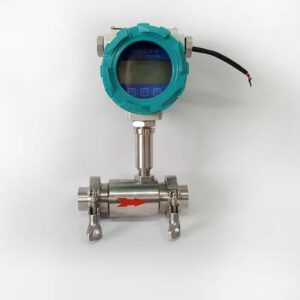
Figure 6 — Heavy industrial environments with large-diameter piping, high-pressure steam, and aggressive chemicals favor rugged conventional technologies (turbine, orifice, vortex) over delicate capillary-based TMCs. Application context always drives technology selection.
Decision Matrix: Quick Comparison and Selection Guidelines
Head-to-Head Performance Comparison Table (Excel-Style)
| Criterio de selección | TMC (Thermal) | Rotámetro | DP / Orifice | Turbina | Vórtice |
|---|---|---|---|---|---|
| Measurement Type | Mass Flow ✓ | Volumetric | Volumetric | Volumetric | Volumetric |
| Accuracy (Best Case) | ±0.5% Rd | ±2–5% FS | ±0.75–2% AR | ±0.5–1% Rd | ±0.5–1.5% Rd |
| Relación de reducción | 100:1 (up to 200:1) | 10:1 | 3:1 | 20:1 | 10:1 |
| T/P Compensation Required? | No — inherent | Sí | Sí | Sí | Sí |
| Setpoint Response Time | <200 ms | Manual only | 500 ms–2 s | ~500 ms | ~500 ms |
| Moving Parts? | Ninguno | Flotador | Ninguno | Rotor + bearings | Bluff body only |
| Digital Integration (DCS/SCADA) | Full (HART/Modbus/EIP) | Ninguno | Via DP transmitter | Yes (pulse/4–20 mA) | Yes (4–20 mA/HART) |
| Dirty / Particulate Gas? | No — clogs capillary | Limitado | Yes (with care) | Clean gas only | Sí |
| Typical Unit Cost (DN15–25) | $800–$4,000 | $50–$300 | $200–$800 (plate) | $400–$1,500 | $500–$2,500 |
| Intervalo de calibración | 6–24 months | Annual visual only | Annual (plate inspection) | Annual (bearing check) | 2–3 years typical |
| GMP / Electronic Batch Record | Yes — full audit trail | No | Partial (via DCS) | Yes (with transmitter) | Yes (with transmitter) |
| High Temperature (>150°C)? | No (typically <100°C) | Limited (metal tubes) | Sí | Yes (special bearings) | Yes (up to 400°C) |
Sources: Fox Thermal flow meter comparison (2024); Metlan Instrument TMC guide; e2g.com DP meter overview; Alicat Scientific turndown documentation; Jade Ant Instruments flow meter selection guide.
Industry Example Mapping
🔬 Choose a TMC When…
- Semiconductor CVD/ALD/Etch: gas purity and ratio tolerance <1%
- Pharmaceutical API synthesis: FDA 21 CFR Part 11 batch records required
- Bioprocess fermentation: O₂/CO₂ sparging with dissolved O₂ setpoint control
- Gas blending panels: certified reference mixture preparation (ISO 6143)
- Catalyst test rigs: reproducible gas composition across months of trials
- Process with frequent gas type changes requiring digital recipe management
- Any application where ±1% mass flow error changes a measurable product outcome
⚙️ Choose a Conventional Meter When…
- Compressed air monitoring: utility tracking, leak detection (±5% adequate)
- Steam metering: high-temperature, high-pressure headers (orifice / vortex)
- Oil & gas wellhead: rugged turbine or DP meter for high-vibration environment
- Cooling water flow indication: visual confirmation on heat exchangers
- Purge gas tank blanketing: simple on/off visual confirmation
- Large-diameter process gas (>DN100) where TMC equivalents are unavailable
- CapEx-constrained non-critical utility measurements with stable conditions
Deployment Considerations: Integration, Maintenance, and Calibration
When deploying TMCs in a new or brownfield facility, four deployment factors consistently determine real-world performance versus datasheet expectations. First, upstream gas conditioning — all TMC capillary sensors require a 7-micron or finer in-line filter upstream, renewed annually or on differential pressure rise. Skipping this step is the leading cause of premature TMC fouling in chemical plant environments.
Second, communication configuration — a TMC communicating via RS-485 Modbus at 19,200 baud with the plant DCS will deliver real-time diagnostics (valve position, sensor temperature, flow stability flag) that justify the device cost in planned maintenance savings alone. Teams that wire TMCs with analog 0–5V output only and never configure the digital interface are leaving this diagnostic value on the table.
Third, calibration scheduling — NIST guidelines recommend calibration intervals be determined by measurement stability history, not a fixed calendar. For a TMC in a clean semiconductor environment, 24-month intervals are achievable with in-between zero-point checks. For a TMC in a corrosive specialty gas application, 6-month full recalibration is more appropriate. The Zero Instrument calibration interval guide provides a structured methodology for interval determination.
Fourth, supplier selection and service support — a TMC is only as reliable as the service network behind it. Procurement teams evaluating suppliers should confirm factory calibration traceability documentation, local service support, and replacement lead times before committing to a multi-unit deployment. Teams working with Jade Ant Instruments for their flow meter programs have found that consolidating meter procurement across a facility — from utility turbine meters to precision TMC equivalents — under a single technically capable supplier simplifies both calibration management and spare-parts inventory, particularly in mixed-technology plants where both TMC-class and conventional meters coexist.
5-Year Total Cost of Ownership: TMC vs. Conventional
The unit price of a TMC ($800–$4,000) looks expensive against a rotameter ($50–$300) or an orifice plate ($200–$800). But for gas-critical applications, total cost of ownership over 5 years routinely reverses the decision. The following figures are based on a single gas control point in a pharmaceutical process (DN15, N₂ blanketing, continuous operation):
Digital TMC
$8,200Unit $1,800 + install $400 + 5yr calibration $2,000 + maintenance $500 + gas savings (−$4,500 N₂ waste avoided) + zero batch losses
Rotámetro
$14,600Unit $180 + install $120 + 5yr calibration $500 + manual logging labor $1,800 + 2 off-spec batches @ $6,000 each = $12,000 + gas waste
DP / Orifice
$9,800Unit $600 + install $800 + DP transmitter $1,200 + 5yr calibration $2,200 + pressure loss energy cost $1,400 + 1 off-spec event $3,600
Contador de turbina
$7,400Unit $700 + install $400 + 5yr calibration $1,500 + bearing replacement $300/yr ($1,500) + gas waste from T/P drift $3,300
Conclusion: A Concise Decision Framework

Figure 7 — The right flow meter decision is a function of process requirements, not brand loyalty. A structured five-question framework covers the vast majority of real-world selection scenarios.
The trade-off between TMCs and conventional meters is not about which technology is “better” — it is about matching instrument capability to process requirements. Overspending on TMCs for utility monitoring wastes capital. Underspending on rotameters for GMP gas control creates compliance and quality risk that dwarfs the instrument savings.
Apply this five-question decision framework before specifying:
- Does the process spec define flow in mass or molar units? → If yes, use a TMC or mass-compensated meter.
- Does a 1–2% flow error produce a measurable negative process outcome? → If yes, use a TMC.
- Is the gas clean, dry, and compatible with capillary sensor materials? → If no, evaluate alternative TMC architectures or conventional meters.
- Is temperature or pressure unstable at the measurement point? → If yes, TMC’s inherent mass-reference eliminates compensation error.
- Is a GMP electronic audit trail required? → If yes, TMC with digital communication is the only compliant choice among the options compared here.
For applications where multiple flow meter technologies must be compared across a facility — including both TMC-class instruments and conventional turbine, electromagnetic, or vortex meters — the Jade Ant Instruments manufacturer comparison guide provides a structured overview of leading suppliers across technology categories. Engineers specifying for the first time should also consult this five-factor flow meter selection guide for a broader instrumentation decision framework.
For deep dives into specific competing technologies, the following high-authority references are recommended: Bronkhorst’s thermal measurement knowledge base covers the physics of capillary sensing in rigorous detail; the Alicat thermal-vs-DP comparison guide is the most technically precise head-to-head available for laboratory and light industrial TMC selection; and the Fox Thermal technology comparison covers the full spectrum of industrial gas flow technologies across the key practical selection criteria.
Finally: validate with actual process gas and conditions, not just datasheet specifications. A TMC calibrated on N₂ and deployed on a 70% H₂ / 30% N₂ mixture without a verified conversion factor will perform worse in practice than a well-calibrated turbine meter on the same service. The instrument specification is only the start of the measurement system design — installation, commissioning, calibration, and maintenance complete it.
Need Expert Flow Meter Guidance?
Whether you’re specifying your first TMC system or auditing an existing conventional meter installation, Jade Ant Instruments can help match the right technology to your exact process requirements.
Explore Flow Meter Solutions →❓ Preguntas frecuentes
What is the main difference between a thermal mass flow controller and a conventional flow meter?
The fundamental difference is what they measure and whether they control. A Thermal Mass Flow Controller (TMC) measures gas flow in true mass units (sccm, slm, g/h) using heat transfer principles — no external temperature or pressure compensation is needed. It also actively regulates flow via an integrated proportional control valve. Conventional flow meters (rotameters, orifice plates, turbine meters) measure volumetric flow — they count volume, not mass. To convert volumetric flow to mass flow requires knowledge of gas density, which changes with temperature and pressure. Conventional meters also do not actively control flow; they only indicate it.
In practical terms: if your supply pressure changes by 20%, a TMC’s mass flow reading stays accurate and its setpoint control remains valid. A rotameter under the same pressure change will indicate the same flow scale position but is actually delivering approximately 10% more or less gas by mass, invisibly.
In which industries is a thermal mass flow controller typically preferred over conventional meters?
TMCs are the preferred or mandatory choice in semiconductor fabrication (CVD, ALD, etch — where gas stoichiometry defines transistor dimensions), pharmaceutical manufacturing (bioreactor sparging, API synthesis, GMP batch records under FDA 21 CFR Part 11), specialty chemical processing (catalytic reactions with defined reactant ratios), gas blending and calibration gas production (reference mixture standards per ISO 6143), and R&D laboratory environments where experimental reproducibility depends on precise, repeatable gas delivery.
In these sectors, a 1% mass flow error has measurable consequences — film thickness non-uniformity, failed cell culture batches, off-spec catalyst performance, or invalid calibration standards. Conventional meters cannot reliably hold these tolerances across varying process conditions.
How does gas type affect thermal mass flow controller choice and maintenance?
Gas type affects TMC selection in three ways. First, conversion factor (CF) accuracy: TMCs are calibrated on a reference gas (usually N₂). For every other gas, a CF derived from the gas’s specific heat and density must be applied. For common gases (Ar, O₂, CO₂, H₂, CH₄), manufacturers publish validated CFs. For exotic mixtures or reactive gases, CFs may need experimental verification. An incorrect CF is the most common source of TMC systematic error.
Second, material compatibility: corrosive gases (Cl₂, HF, HCl, BCl₃) require TMCs with special wetted materials — typically Hastelloy C-22, PTFE-lined bodies, and metal-to-metal seals. Standard 316SS TMCs will corrode in weeks in these services. Third, calibration interval: reactive gases degrade sensor surfaces faster, typically requiring 6-month recalibration versus 12–24 months for inert gases like N₂ or Ar.
What is turndown ratio, and why does it matter for flow meter selection?
Turndown ratio (also called rangeability) is the ratio of a meter’s maximum measurable flow to its minimum measurable flow while maintaining accuracy specification. A 100:1 turndown TMC rated for 100 sLm full scale can accurately measure flows down to 1 sLm. An orifice plate with a 3:1 turndown rated for 100 sLm loses accuracy below approximately 33 sLm.
This matters because most industrial processes do not run at constant full-scale flow. A reactor with a normal flow of 30 sLm but startup purge flow of 100 sLm needs a meter that is accurate at both extremes. A TMC handles this with a single device. With an orifice plate, you would either need two parallel meters (one sized for startup, one for normal operation) or accept inaccurate readings during one phase — both increasing cost and complexity.
Can a thermal mass flow controller measure liquid flow, or only gases?
Standard bypass capillary-type TMCs are designed exclusively for gas measurement. The physics of capillary thermal sensing work optimally for low-viscosity, compressible fluids with well-characterized specific heat values. Liquid in a gas TMC capillary causes condensation measurement errors, potential sensor corrosion, and in the worst case, liquid blockage of the capillary sensor.
However, specialized liquid thermal mass flow controllers (sometimes called Coriolis-thermal devices or micro-Coriolis controllers) do exist for precise liquid dosing — Bronkhorst’s CORI-FLOW series is a well-known example. These use different measurement geometries optimized for liquid properties. For liquid flow control applications, Coriolis mass flow controllers are generally the higher-accuracy benchmark technology, while thermal devices serve low-flow specialty liquid applications.
How often does a thermal mass flow controller need to be calibrated?
Calibration interval depends on gas service, process criticality, and measured drift history. General industry guidelines suggest:
6 months: Reactive or corrosive gases (Cl₂, HF, BCl₃, silane); TMCs in high-humidity or contaminated environments; devices in FDA-regulated processes where batch records must meet regulatory accuracy requirements.
12 months: Standard practice for most industrial TMC applications. Sufficient for clean inert gases (N₂, Ar) in well-maintained systems.
24 months: Achievable for clean gas semiconductor applications with documented zero-point stability monitoring between full calibrations. Major fabs use daily automated zero-checks to verify between annual ISO-traceable lab calibrations.
NIST GMP-11 guidelines recommend that calibration intervals be set based on measurement uncertainty history, not a fixed calendar — a TMC that consistently shows <0.3% drift at 12 months can justify a 24-month interval. One showing 1.5% drift at 6 months should be investigated for contamination or gas incompatibility before extending the interval.
What is a gas conversion factor (CF) and how can errors be avoided?
A conversion factor (CF) is a dimensionless multiplier applied to a TMC’s indicated flow (referenced to the calibration gas, usually N₂) to calculate the actual flow of a different gas. The CF is derived from the ratio of the gas’s specific heat capacity and density relative to N₂ under standard conditions.
For example, argon has a lower specific heat than N₂, so less heat is transferred per unit mass. The same ΔT signal indicates higher-than-actual flow. Without correction, an N₂-calibrated TMC measuring Ar will over-read by approximately 20%. The published Ar CF (typically ≈0.83) corrects this: Actual Ar flow = Indicated N₂-equivalent reading × 0.83.
To avoid CF errors: (1) maintain a documented gas-to-CF mapping for every TMC in the facility; (2) include CF verification as part of every process change review; (3) use multi-gas TMC firmware (available from Bronkhorst, MKS, Alicat, Brooks) that stores CFs for dozens of gases and allows field selection without hardware changes; (4) for exotic gas mixtures, calculate CF from first principles or request factory gas-specific calibration.
When is a differential pressure (orifice plate) flow meter a better choice than a TMC?
DP orifice plate meters remain the correct choice in specific scenarios despite their limited 3:1 turndown and required T/P compensation: (1) High-temperature and high-pressure steam service (100–400°C, >10 bar) where TMC sensor materials fail; (2) Large pipe diameters (DN150+) where no TMC equivalent exists; (3) Dirty or aggressive gas streams (with particulates, condensates) where a capillary-based TMC would clog; (4) Very low-cost utility metering where ±2% accuracy is adequate and there is no capital budget for premium instrumentation; (5) Existing installations with sunk piping costs around standard flange orifice runs where replacing with TMC technology requires full piping rework.
The DP orifice plate’s key advantages are its zero moving parts, extremely rugged construction, gas- and liquid-compatibility, wide pipe size availability, and a global installed base supported by a mature calibration and replacement infrastructure.
How do I choose between a TMC and a turbine flow meter for gas service?
The decision hinges on five parameters: (1) Mass vs. volumetric need: if you need mass flow (as most gas-phase processes do), TMC is the direct answer; turbine requires density compensation. (2) Accuracy at variable conditions: TMC maintains ±0.5% Rd across temperature/pressure variation; turbine accuracy degrades without compensation and its bearings wear, shifting its K-factor. (3) Gas cleanliness: turbines require particle-free gas to protect bearings; TMCs require particle-free gas to protect capillaries — both need filtration. (4) Operating environment: turbine meters tolerate vibration and shock better than delicate TMC capillaries; for outdoor or mechanical environments, turbine has an edge. (5) Control vs. indication: a turbine meter only medidas; a TMC both measures and controls — if you need a control valve anyway, a TMC eliminates a separate valve and actuator cost.
What should engineers verify when commissioning a new thermal mass flow controller?
A thorough TMC commissioning checklist covers seven areas: (1) Gas CF verification — confirm the correct conversion factor is programmed for the actual process gas, not just the default N₂ calibration gas. (2) Zero-point check — with upstream valve closed and no gas flowing, confirm the TMC reads zero (or within its zero-stability spec). Adjust zero if needed per manufacturer procedure. (3) Leak test — pressure-test all connections per SEMI F1 or equivalent standard before introducing process gas. (4) Warm-up time — allow 5–30 minutes thermal stabilization before trusting readings on traditional bypass TMCs. (5) Communication verification — confirm DCS/SCADA readback matches TMC local display at known setpoints. (6) Full-scale flow verification — where possible, verify at 100%, 50%, and 10% of full scale against a traceable reference (bubble meter, critical orifice, or NIST-traceable secondary standard). (7) Calibration certificate review — confirm the factory calibration certificate documents calibration gas, reference standard traceability (NIST or equivalent), date, and acceptance criteria before the device enters service.