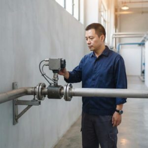

Non-invasive metering technologies have fundamentally changed the way engineers, facility managers, and plant operators measure flow, energy, and process variables. Instead of cutting pipes, shutting down systems, and dealing with contamination risks, clamp-on and transit-time meters allow measurements to be taken from outside the pipe wall — without any interruption to the process running inside.
For residential building managers tracking chilled water consumption in HVAC loops, and for industrial process engineers monitoring chemical flows in pharmaceutical plants, the core promise is the same: accurate measurement without physical intrusion into the pipe. However, the two dominant non-invasive technologies — clamp-on meters and transit-time meters — differ in meaningful ways that directly affect accuracy, installation complexity, total cost, and which applications they serve best.
This comparison guide examines both technologies across every dimension that matters to decision-makers: working principles, accuracy benchmarks, installation requirements, safety, lifecycle cost, integration with building management systems (BMS) and SCADA platforms, limitations, and practical decision frameworks. By the end, you will know which technology fits your specific scenario — and why.
Overview of Non-Invasive Metering Technologies
Clamp-On Meters at a Glance
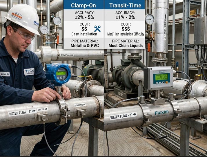
Clamp-on meters mount externally on the pipe surface using transducer assemblies that are physically clamped or strapped to the outside wall. They send ultrasonic signals through the pipe wall and into the flowing fluid without requiring any penetration, cutting, or welding. The most widely deployed clamp-on meters use either transit-time or Doppler measurement principles — though in common industry usage, “clamp-on” often refers specifically to the installation method rather than the measurement principle.
The defining advantage of clamp-on devices is their truly non-invasive nature. In a 2025 field study published in Measurement (Elsevier), seven different clamp-on transit-time ultrasonic flowmeters were tested under both favorable laboratory and industrial measurement conditions, with results confirming that properly installed clamp-on devices can deliver accuracy within ±1% of reading in favorable conditions — though field performance can degrade to ±2–5% when pipe wall conditions, liner thickness, or installation geometry introduce uncertainties (Luca et al., Measurement, 2025).
Transit-Time Meters at a Glance
Transit-time meters measure the difference in travel time between ultrasonic pulses sent upstream and downstream through the fluid. This principle can be implemented in clamp-on, insertion, or inline (spool-piece) configurations. When people refer to “transit-time meters” as a distinct category from “clamp-on,” they often mean inline or insertion transit-time devices — where the transducers have direct acoustic contact with the fluid through wetted ports or a dedicated pipe section.
Inline transit-time meters typically achieve higher accuracy (±0.5% or better) because the transducers couple directly with the fluid rather than transmitting signals through the pipe wall. This eliminates the acoustic uncertainties introduced by wall thickness, pipe material, liner composition, and coupling gel quality — all factors that affect clamp-on performance. However, inline transit-time devices require pipe cutting and process shutdown for installation, which partially sacrifices the non-invasive advantage.
How Clamp-On Meters Work
Principle of Operation
A clamp-on ultrasonic flow meter uses two transducers mounted on the outside of a pipe. The transducers alternate between transmitting and receiving ultrasonic pulses. One transducer sends a pulse downstream (in the direction of flow), while the other sends a pulse upstream (against the flow). Because the flowing fluid carries the downstream signal slightly faster and retards the upstream signal slightly slower, a measurable time difference (Δt) develops between the two signals. This Δt is directly proportional to the average fluid velocity along the ultrasonic path.
The meter’s processor uses this velocity measurement, combined with the known pipe inner diameter, to calculate volumetric flow rate. The governing relationship is:
V = (D / 2sinθcosθ) × (Δt / tup × tdown)
Where V is fluid velocity, D is pipe inner diameter, θ is the transducer mounting angle, and tup and tdown are the upstream and downstream transit times respectively.

Typical Sensors and Signal Attributes
Clamp-on transducers are typically piezoelectric ceramic elements encased in a rugged housing. They operate at frequencies between 0.5 MHz and 4 MHz, with lower frequencies used for larger pipes (better penetration through thicker walls) and higher frequencies used for smaller pipes (better resolution). The signal must pass through the pipe wall twice (out and back) in a V-path configuration, or once in a Z-path (direct diagonal) configuration, depending on pipe diameter and wall characteristics.
Signal quality depends heavily on the acoustic coupling between the transducer and the pipe wall. A couplant compound — typically a specialized gel or silicone pad — fills microscopic air gaps between the transducer face and the metal surface. Air gaps as small as 0.1 mm can attenuate the ultrasonic signal by 20 dB or more, which is why coupling quality is one of the most critical installation variables. Jade Ant Instruments’ ultrasonic flow meter series, for example, uses IP68-rated sensor housings designed to maintain coupling integrity across temperature cycles from -30°C to +160°C.
How Transit-Time Meters Work
Principle of Operation
The transit-time measurement principle is fundamentally the same whether implemented in a clamp-on or inline configuration: measure the time difference between upstream and downstream ultrasonic pulses. The critical distinction for inline (or insertion) transit-time meters is that the transducers are in direct acoustic contact with the fluid — either mounted flush with the pipe wall through wetted ports, or integrated into a spool piece that replaces a section of pipe.
This direct contact eliminates the need for the signal to travel through the pipe wall material, which removes several sources of measurement uncertainty: variations in pipe wall thickness, unknown or non-uniform wall material properties, liner attenuation, and coupling gel degradation. The result is a cleaner, stronger signal with a more predictable acoustic path — which directly translates to better accuracy and faster response times.
Measurement Approach and Signal Interpretation
Advanced inline transit-time meters use multiple ultrasonic paths (multi-path designs) to sample the velocity profile across the entire pipe cross-section, rather than relying on a single diagonal path. A four-path or five-path meter, for example, sends beams through different chordal positions to detect asymmetric flow profiles that a single-path meter would miss. This is why multi-path inline transit-time meters routinely achieve ±0.2–0.5% accuracy even in imperfect flow conditions — a level that single-path clamp-on meters cannot match under real-world installation constraints.
Multi-path meters also provide built-in diagnostic capabilities: by comparing the velocity readings across different paths, the meter can detect and report swirl, asymmetry, and profile distortions. These diagnostics are valuable both for verifying measurement integrity and for identifying upstream piping issues that may need correction.
Watch: How Transit-Time Ultrasonic Flow Meters Work
Video credit: Siemens — Principles of ultrasonic flow measurement in industrial clamp-on applications.
Key Performance Metrics: Accuracy and Response Time
Accuracy Benchmarks and Calibration
Accuracy is the single metric that most often drives the choice between clamp-on and inline transit-time technologies. The table below compiles typical accuracy specifications based on manufacturer data sheets and independent field studies:
| Parameter | Clamp-On (Single-Path) | Clamp-On (Dual-Path) | Inline Transit-Time (Single-Path) | Inline Transit-Time (Multi-Path) |
|---|---|---|---|---|
| Accuracy (% of reading) | ±1.0% to ±2.0% | ±0.5% to ±1.0% | ±0.5% to ±1.0% | ±0.15% to ±0.5% |
| Repeatability | ±0.2% to ±0.5% | ±0.15% to ±0.3% | ±0.1% to ±0.2% | ±0.05% to ±0.15% |
| Turndown Ratio | Up to 100:1 | Up to 150:1 | Up to 200:1 | Up to 400:1 |
| Response Time | 0.5–2 seconds typical | 0.3–1 second typical | 0.1–0.5 seconds | 0.05–0.2 seconds |
| Pipe Diameter Range | DN25 – DN6000 | DN50 – DN3000 | DN15 – DN1200 | DN50 – DN3000+ |
| Calibration Method | Factory calibration; field dry calibration | Factory calibration; in-situ verification | Wet calibration (flow rig) | Wet calibration + in-situ diagnostics |
Sources: Aggregated from manufacturer specifications including Siemens SITRANS, FLEXIM, Badger Meter, and Jade Ant Instruments ultrasonic meter product line. Actual field accuracy depends on installation quality, pipe condition, and fluid properties.
The accuracy gap between clamp-on and inline transit-time is not a technology deficiency — it is a physics reality. When ultrasonic signals must pass through a pipe wall (which may be corroded, scaled, or imprecisely characterized), uncertainty enters the measurement that does not exist when signals travel directly through the fluid. This is why custody-transfer applications in the oil and gas sector almost exclusively use inline multi-path transit-time meters meeting API MPMS Chapter 5.8 standards, while process monitoring and energy sub-metering applications frequently use clamp-on devices where ±1–2% accuracy is acceptable.
Response Time and Dynamic Range
Response time matters most in applications involving rapidly changing flow rates — batch dosing, demand-based pump control, or safety shutdown systems. Inline transit-time meters with digital signal processing can update readings in as little as 50 milliseconds, which allows control systems to react to flow changes almost instantaneously. Clamp-on meters, because of the additional signal processing needed to filter out pipe wall reflections and noise, typically respond in 0.5 to 2 seconds — adequate for steady-state monitoring but potentially too slow for fast-loop control.
Dynamic range (turndown ratio) is another differentiator. Multi-path inline meters can maintain specified accuracy over turndown ratios of 400:1 or more, meaning they remain accurate from maximum flow down to 0.25% of maximum. Single-path clamp-on meters typically offer 100:1 turndown, which is still excellent for most monitoring applications but may be insufficient for processes that operate across very wide flow ranges.
Accuracy Performance by Application Type
Typical Accuracy: Clamp-On vs Inline Transit-Time by Application
Accuracy (% of reading)
HVAC Energy
±2.0%
±1.0%
Municipal Water
±1.5%
±0.5%
Chemical Process
±1.5%
±0.2%
Custody Transfer
±1.0%
±0.15%
Clamp-On
Inline Transit-Time
0%
Chart shows representative accuracy achievable with proper installation. Clamp-on accuracy in custody-transfer scenarios often requires additional in-situ calibration to reach ±1.0%. Inline multi-path meters can achieve ±0.15% for fiscal metering per API 5.8.
Installation Considerations
Setup Steps for Clamp-On Devices
Installing a clamp-on flow meter involves six primary steps that, when followed precisely, are the difference between a ±1% measurement and a ±5% guess:
Step 1 — Pipe Characterization: Measure and record the outer diameter, wall thickness, and identify the pipe material (carbon steel, stainless steel, PVC, copper, etc.) and any internal liner. Input these parameters into the meter’s configuration. An error of just 1 mm in wall thickness on a DN100 steel pipe can shift the reading by 2–3%.
Step 2 — Location Selection: Choose a section of pipe that is always full of liquid, on a straight run with at least 10 pipe diameters of unobstructed pipe upstream and 5 diameters downstream. Avoid locations immediately after pumps, partially open valves, elbows, or tee junctions.
Step 3 — Surface Preparation: Clean the pipe surface at the transducer mounting locations down to bare metal or a smooth surface. Remove paint, rust, scale, and any debris. The surface must be smooth enough for the couplant to create an air-free bond.
Step 4 — Couplant Application: Apply a generous layer of acoustic coupling gel or install a solid-state coupling pad between the transducer face and the pipe surface. There must be zero air gaps — air is an ultrasonic insulator.
Step 5 — Transducer Mounting: Mount the transducers at the spacing distance calculated by the meter (based on pipe parameters and selected mounting method — V-path or Z-path). Secure the transducers using the mounting fixture, straps, or clamps. Verify alignment is straight and the transducers are at the correct angular position.
Step 6 — Signal Verification: Power on the meter and verify signal strength, signal quality (Q-value), and transit-time readings. Most modern meters display a signal quality indicator that should exceed 60–80% for reliable measurement. If signal quality is low, re-check coupling, alignment, and pipe parameters.
Setup Steps for Transit-Time Devices
Inline transit-time meter installation is more involved mechanically but simpler from an acoustic coupling perspective:
The process requires cutting the pipe and installing a spool piece (for full-bore meters) or drilling a tapping point and inserting a probe (for insertion-type meters). Pipe must be drained and depressurized — meaning a process shutdown or bypass is required. Flanged connections must be aligned, gaskets checked, and bolts torqued to specification. After mechanical installation, the meter is powered on, fluid parameters are entered, and a zero-flow verification is typically performed. Because the transducers are in direct contact with the fluid, there is no coupling gel to degrade and no pipe wall to characterize — the acoustic path is defined by the precision-machined spool piece, making calibration more stable over time.
Mounting, Access, and Maintenance Considerations
Both technologies require ongoing access for inspection and, occasionally, maintenance. For clamp-on meters, the primary maintenance activity is checking and refreshing the acoustic couplant — which can dry out, harden, or wash away over 1–3 years depending on environmental conditions. The Jade Ant Instruments ultrasonic flow meter line addresses this with IP68-rated sensor housings that protect both the transducer element and the couplant layer from moisture and temperature extremes.
For inline meters, mechanical maintenance involves periodic gasket inspection and, in rare cases, transducer replacement (typical lifespan exceeds 15 years). Neither technology has moving parts, so there are no bearings, gears, or impellers to wear out — a significant lifecycle advantage over mechanical flow meters.

Safety and Electrical Isolation
Isolation Ratings and Safety Standards
Non-invasive meters offer inherent safety advantages because they do not penetrate the process boundary. There is no risk of leaks from sensor ports, no potential for fluid exposure during maintenance, and no possibility of introducing contamination. This makes them particularly valuable in hazardous fluid applications (toxic chemicals, high-temperature steam, cryogenic liquids) and in classified hazardous areas where reducing the number of pipe penetrations minimizes leak points.
From an electrical perspective, clamp-on meters provide galvanic isolation between the measurement electronics and the process fluid by default — the pipe wall itself serves as an insulating barrier. Most industrial-grade non-invasive meters carry certifications including IEC 61010-1 (safety requirements for measurement equipment), and many are available in ATEX/IECEx-certified versions for Zone 1 or Zone 2 hazardous areas per the IECEx certification system.
Impact on System Grounding and Fault Tolerance
Because clamp-on transducers mount on the pipe exterior, they do not affect the internal grounding continuity of the piping system — an important consideration in process plants where cathodic protection or electrical bonding systems are in place. Inline meters, by contrast, introduce flanged connections that may need bonding jumpers to maintain electrical continuity across the meter. In facilities governed by NFPA 70 (National Electrical Code) or equivalent standards, the grounding implications of any inline installation must be evaluated during design.
Cost of Ownership: Upfront and Operating Costs
Purchase Price and Licensing
The purchase price gap between clamp-on and inline transit-time meters varies by pipe size, accuracy class, and feature set. The table below provides representative pricing ranges based on 2025–2026 market data:
| Meter Type | Small Pipe (DN25–100) | Medium Pipe (DN100–300) | Large Pipe (DN300–1000+) |
|---|---|---|---|
| Clamp-On (Single-Path, Fixed) | $800 – $2,500 | $1,500 – $4,000 | $3,000 – $8,000 |
| Clamp-On (Dual-Path, Fixed) | $2,000 – $5,000 | $3,500 – $7,000 | $5,000 – $12,000 |
| Portable Clamp-On | $2,000 – $6,000 (universal kit covering multiple pipe sizes) | ||
| Inline Transit-Time (Single-Path) | $1,500 – $4,000 | $3,000 – $8,000 | $6,000 – $15,000 |
| Inline Transit-Time (Multi-Path) | $5,000 – $12,000 | $8,000 – $20,000 | $15,000 – $50,000+ |
Pricing data compiled from distributor listings, manufacturer quotations, and industry pricing guides (BCST Group, 2026). Prices do not include installation labor, pipe modification, or ancillary equipment. Jade Ant Instruments offers competitive pricing for clamp-on and inline ultrasonic meters with direct factory-to-customer delivery.
Lifecycle Costs: Maintenance, Replacements, and Energy Usage
Purchase price alone tells an incomplete cost story. A clamp-on meter that costs $2,000 but requires zero pipe cutting, zero process shutdown, and can be installed by one technician in 45 minutes has a dramatically lower total installed cost than an inline meter that costs $3,000 but requires two days of pipe work, a welding crew, process drain-down, and a safety permit. In retrofit scenarios, the installation cost of an inline meter can exceed the meter price by 3–5 times.
Over a 10-year lifecycle, the ongoing costs for both technologies are relatively low — neither has moving parts, and neither consumes significant energy (typical power consumption is under 10 watts). The key lifecycle cost differentiator is calibration verification: inline meters maintain more stable calibration because their acoustic path geometry is fixed, while clamp-on meters may need periodic signal quality checks and couplant maintenance that add modest labor costs.
Total Cost of Ownership Breakdown
10-Year TCO Breakdown: Clamp-On Meter (Typical Industrial)
Purchase Price (18%)
Installation (8%)
Calibration/Verification (22%)
Maintenance (15%)
Downtime Risk (25%)
Energy/Operating (12%)
Approximate cost allocation over a 10-year period for a fixed clamp-on ultrasonic meter in a typical industrial installation. Downtime risk (cost of measurement failure × probability) is often the largest hidden cost component. Data synthesized from TCO analyses by Emerson Automation Solutions and independent consulting reports.
Downtime Impact and Reliability Factors
Reliability in the context of non-invasive meters means: how likely is the meter to continue producing accurate readings without unplanned intervention? Both clamp-on and inline transit-time meters have excellent reliability track records — mean time between failure (MTBF) figures exceeding 100,000 hours are common. However, the consequences of failure differ. A failed clamp-on meter can typically be replaced or repaired without stopping the process (simply unclamp the old transducers and mount new ones). A failed inline meter may require a process shutdown, pipe isolation, and mechanical work to access the spool piece — a much more disruptive and expensive event.
This asymmetry in failure consequences is why many industrial operators install clamp-on meters as redundant check meters alongside inline primary meters. The clamp-on device provides an independent verification point that can flag drift in the primary meter, and if the primary fails, the clamp-on can serve as a temporary replacement while repairs are scheduled. Jade Ant Instruments’ range of industrial flow monitors includes both fixed and portable ultrasonic options suited for this dual-role deployment strategy.
Best-Use Scenarios: Residential vs Industrial
Residential Suitability and Common Applications
In residential and light-commercial settings — apartment complexes, office buildings, retail facilities — non-invasive meters are most commonly used for HVAC energy sub-metering and domestic water flow monitoring. Clamp-on meters dominate this segment because they can be installed by a single technician in under an hour without disrupting building operations, and their ±1–2% accuracy is well within the requirements for energy billing and consumption monitoring.
Typical residential and commercial applications include chilled water and hot water loop metering in central HVAC systems, where the meter is paired with temperature sensors to calculate thermal energy (BTU or kWh). Clamp-on transit-time meters work well in these clean-water systems because the fluid is typically treated and free of significant particulates. Several building codes and green-building standards — including ASHRAE 90.1 and LEED certification requirements — now mandate or incentivize sub-metering of energy consumption, which has driven adoption of clamp-on meters in commercial buildings.
Industrial Scale, Compliance, and Integration Needs
Industrial applications impose more demanding requirements across every dimension: accuracy, reliability, environmental resilience, safety certification, and data integration. In pharmaceutical manufacturing, for instance, flow measurements used in batch records must meet FDA 21 CFR Part 11 data integrity requirements, which often drives the selection toward inline meters with built-in audit trails and tamper-resistant data logging. In oil and gas custody transfer, measurement uncertainty translates directly into revenue: a 0.5% error on a pipeline moving 100,000 barrels per day represents $30,000–$50,000 per day in unaccounted product at typical crude oil prices.
For industrial process monitoring where the primary objective is control optimization rather than fiscal metering — monitoring cooling water flow to heat exchangers, tracking chemical feed rates, or verifying fire suppression system readiness — clamp-on meters offer a compelling combination of adequate accuracy, easy installation, and zero process interference.
System Integration Considerations with Existing BMS/SCADA
Modern non-invasive meters from both categories support standard industrial communication protocols: 4–20 mA analog output, pulse output, RS-485 Modbus RTU, HART, and, increasingly, Modbus TCP/IP and OPC UA for direct Ethernet integration. The choice of protocol depends on the existing automation infrastructure:
For building management systems (BMS) such as Honeywell Niagara, Johnson Controls Metasys, or Schneider EcoStruxure, BACnet/IP or Modbus TCP integration is most common. Clamp-on meters with built-in BACnet output simplify integration by eliminating the need for protocol converters.
For industrial SCADA systems — Allen-Bradley, Siemens WinCC, Wonderware, or Yokogawa CENTUM — 4–20 mA with HART overlay is the traditional standard, though Modbus and Profibus/Profinet are increasingly used. Multi-path inline transit-time meters often include more extensive diagnostic data accessible via HART or digital fieldbus protocols, which can be valuable for predictive maintenance programs.
Jade Ant Instruments’ ultrasonic flow meters support 4–20 mA, RS-485 Modbus, and HART communication protocols, providing flexible integration with both BMS and SCADA platforms.
| Protocol | Clamp-On (Typical) | Inline Transit-Time (Typical) | Common Integration Target |
|---|---|---|---|
| 4–20 mA | Yes (standard) | Yes (standard) | PLC, SCADA, DCS |
| Pulse Output | Yes | Yes | Totalizers, flow computers |
| RS-485 Modbus RTU | Yes (standard or optional) | Yes (standard) | SCADA, BMS, data loggers |
| HART | Optional on premium models | Yes (standard on most) | DCS, asset management systems |
| Modbus TCP/IP | Optional / emerging | Available on many models | IT/OT convergence, cloud SCADA |
| BACnet/IP | Rare / via gateway | Rare / via gateway | Building management systems |
| Profibus/Profinet | Rare | Available on some models | Siemens-based DCS/SCADA |
Limitations and Common Challenges
Known Limitations and Failure Modes
No measurement technology is without limitations, and non-invasive meters are no exception. Understanding these limitations before installation — rather than discovering them after commissioning — prevents costly rework and frustration.
Clamp-on meters are sensitive to pipe wall condition, couplant degradation, transducer misalignment, entrained air, and inaccurate pipe parameter input. The most common failure mode in the field is not a hardware failure but a gradual accuracy drift caused by couplant degradation or pipe wall changes that go undetected because the meter continues to display a reading (albeit an increasingly inaccurate one). Without periodic signal quality checks, this drift can persist for months or years.
Inline transit-time meters can be affected by cavitation (at low downstream pressures), deposit buildup on transducer faces, and erosion of transducer windows in abrasive-fluid applications. Multi-path meters are less susceptible to profile-related errors than single-path meters, but they carry higher purchase costs and require more complex spare-parts management.
Environmental Factors and Interference
External environmental conditions can significantly impact measurement performance. Key environmental risks include:
Temperature extremes: Ultrasonic signal velocity in both the pipe wall and the fluid changes with temperature. While modern meters include temperature compensation algorithms, rapid temperature fluctuations (e.g., outdoor pipe exposed to solar heating and nighttime cooling) can introduce transient errors. Insulating the pipe at the sensor location mitigates this.
Electromagnetic interference (EMI): Variable-frequency drives (VFDs), large motors, welding equipment, and high-voltage distribution panels can inject electrical noise into meter electronics. Proper cable shielding, grounded conduit, and separation from power cables (recommended minimum 300 mm) are essential.
Vibration: Pipe vibration from nearby pumps, compressors, or turbulent flow can corrupt the ultrasonic signal. Mounting the meter on a well-supported pipe section away from vibration sources reduces this risk. Some meters include vibration-rejection algorithms, but these have limits.
Moisture and condensation: In humid environments, condensation inside electronic enclosures can cause circuit board corrosion and signal degradation. IP67/IP68 enclosures and desiccant packs or enclosure heaters address this risk.
Mitigation Strategies and Best Practices
The following strategies, drawn from field experience across hundreds of installations, address the most common sources of measurement error:
Perform a pipe survey before ordering the meter. Measure wall thickness with an ultrasonic thickness gauge at multiple points around the circumference — corrosion is rarely uniform. A wall thickness variation of more than 10% around the circumference indicates a challenging installation location.
Use permanent couplant pads (solid-state elastomer) instead of gel for fixed clamp-on installations. Pads maintain coupling integrity for 5+ years without degradation, compared to 1–2 years for gel-type couplants in outdoor environments.
Install flow conditioning elements (tube bundles or plate-type conditioners) upstream if the available straight run is less than the recommended minimum. This is especially important for clamp-on meters, which are more sensitive to profile distortion than multi-path inline meters.
Establish a verification schedule. Compare the non-invasive meter reading against a reference measurement (portable clamp-on meter, volumetric test, or comparison with another process variable) at least annually. This catches drift before it becomes financially significant.

Recommendations and Decision Guide
Quick Decision Framework Based on Application
After analyzing accuracy, cost, installation, safety, and integration factors, the decision between clamp-on and inline transit-time meters reduces to three primary questions:
Question 1: Can you cut the pipe? If no (retrofit, hazardous fluid, no shutdown permitted, cleanroom environment), then clamp-on is the only option.
Question 2: What accuracy do you need? If ±1% or better is acceptable for your application (process monitoring, energy sub-metering, trend tracking), clamp-on is sufficient. If you need ±0.5% or better (custody transfer, fiscal metering, regulatory compliance), inline transit-time with multi-path technology is required.
Question 3: What is the total budget including installation? If the installation cost of an inline meter exceeds the value of the accuracy improvement it provides, clamp-on delivers better ROI. If measurement accuracy has direct financial impact (revenue metering), the higher total cost of inline transit-time is justified.
Scenario Checklists for Choosing Clamp-On vs Transit-Time
| Scenario | Choose Clamp-On When… | Choose Inline Transit-Time When… |
|---|---|---|
| HVAC energy metering | Clean water loop; ±1–2% accuracy acceptable; no pipe cutting desired | High-value energy billing where ±0.5% accuracy justifies installation cost |
| Municipal water distribution | Temporary audit metering; check-metering; locations where shutdown is impractical | Revenue metering at district boundaries; custody transfer points |
| Chemical process monitoring | Corrosive fluids where pipe penetration is hazardous; process monitoring | Batch control requiring fast response; recipe accuracy requirements |
| Oil & gas | Check metering; portable audit surveys; temporary measurements | Fiscal metering per API 5.8; allocation metering; custody transfer |
| Pharmaceutical | Clean-in-place monitoring; utility water metering | FDA-regulated batch records; 21 CFR Part 11 data integrity |
| Retrofit / existing plant | No shutdown available; budget-constrained; temporary or trial measurement | Planned turnaround with budget for pipe work; permanent high-accuracy need |
Final Verdict and Implementation Tips
There is no universally “better” technology between clamp-on and inline transit-time meters. The optimal choice depends entirely on the intersection of your accuracy requirements, installation constraints, and total cost tolerance. What field experience consistently shows is that the majority of measurement problems trace back to installation and configuration errors, not technology limitations. A clamp-on meter installed correctly on the right pipe section will outperform an inline meter installed with misaligned flanges or inadequate straight runs.
For organizations evaluating both technologies, a practical approach is to start with a portable clamp-on meter — such as those available from Jade Ant Instruments — to survey multiple measurement points and characterize flow conditions before committing to permanent installations. This survey data informs whether each point needs clamp-on or inline technology, and identifies installation challenges (short straight runs, pipe condition issues, vibration sources) that can be addressed during the design phase rather than discovered during commissioning.
Watch: Clamp-On Ultrasonic Flow Meter Installation Best Practices
Video credit: Practical installation guide showing correct transducer placement, couplant application, and signal verification procedures.
The choice between clamp-on and transit-time non-invasive meters is not a question of “which is better” but “which is right for this specific measurement point.” Clamp-on meters deliver unmatched installation simplicity, zero process disruption, and adequate accuracy for monitoring and sub-metering applications. Inline transit-time meters provide superior accuracy, faster response, and more stable long-term calibration for fiscal metering and precision process control — but at the cost of pipe work, process shutdown, and higher total installed investment.
The key takeaways from this comparison are: first, match the technology to the accuracy requirement — do not over-specify (paying for ±0.2% when ±1% is sufficient) or under-specify (installing a clamp-on where fiscal-grade measurement is required). Second, invest in proper installation — the difference between a good and poor installation on the same meter can be larger than the difference between meter technologies. Third, plan for lifecycle verification — both technologies drift, and a verification strategy catches problems before they become expensive.
A rigorous vendor evaluation should include requesting field reference installations in similar applications, verifying calibration traceability to national standards (NIST, PTB, or equivalent), confirming communication protocol compatibility with your existing automation platform, and — ideally — conducting a trial measurement on your actual pipe before committing to a permanent installation. Jade Ant Instruments supports this evaluation process by providing technical data sheets, application engineering assistance, and trial units for on-site testing — helping you align meter selection with your actual operating conditions rather than catalog assumptions.
Frequently Asked Questions (FAQ)
1. What factors determine the best non-invasive meter for a given application?
The primary factors are: required measurement accuracy (fiscal metering demands ±0.5% or better, while process monitoring tolerates ±1–2%), whether pipe cutting and process shutdown are feasible, the fluid type and cleanliness, available straight pipe runs, communication protocol requirements for your BMS or SCADA system, and total budget including installation labor. A structured selection guide that evaluates each factor against your specific conditions is the most reliable way to avoid mismatches.
2. How do installation environments affect accuracy for each technology?
Clamp-on meters are more sensitive to installation environment than inline meters. Pipe wall condition (corrosion, scale, paint), ambient temperature swings, vibration, and electromagnetic interference all introduce uncertainty into the acoustic path. Inline transit-time meters, because their transducers contact the fluid directly, are largely immune to pipe wall effects but can still be affected by flow profile distortion from upstream disturbances. In both cases, following manufacturer installation guidelines — especially straight-run requirements and cable routing — reduces environmental impact on accuracy by 50–80% compared to ad-hoc installations.
3. Are there hybrid approaches or hybrid deployments?
Yes, hybrid deployments are common in sophisticated measurement strategies. A typical approach installs inline multi-path transit-time meters at primary fiscal metering points and clamp-on meters at secondary monitoring points throughout the same system. Some advanced ultrasonic meters — such as those from Flexim and Siemens — offer dual-mode operation that can switch between transit-time and Doppler measurement principles depending on fluid conditions. Additionally, portable clamp-on meters are frequently used as “audit tools” to verify fixed inline meter accuracy during periodic checks.
4. Can clamp-on meters achieve custody-transfer accuracy?
Under optimal conditions — clean fluid, precisely characterized pipe, high signal quality, and factory calibration verified against a traceable flow standard — some dual-path clamp-on meters can approach ±0.5% accuracy. However, most custody-transfer standards (including API MPMS Chapter 5.8) specify inline multi-path meters because their accuracy is more stable over time and less dependent on external factors. Clamp-on meters are generally accepted for check-metering and verification purposes within custody-transfer systems, but not as the primary fiscal meter.
5. What pipe sizes work best for clamp-on non-invasive meters?
Clamp-on meters work across a wide range of pipe sizes — from DN25 (1 inch) to DN6000 (236 inches) — but their performance sweet spot is typically DN50 to DN1000 (2 to 40 inches). On very small pipes, the short acoustic path length makes signal resolution challenging. On very large pipes, signal attenuation across the longer path can reduce signal quality. Jade Ant Instruments’ clamp-on ultrasonic meters cover DN32 to DN1000 in standard configurations and DN50 to DN6000 with insertion-type sensors for larger pipes.
6. How often should non-invasive meters be recalibrated?
Industry best practice is to verify measurement accuracy annually. For clamp-on meters, this includes checking signal quality, couplant condition, and comparing readings against a reference measurement. Inline transit-time meters typically maintain calibration stability for 2–5 years, but annual diagnostic checks are still recommended. In regulated industries (pharmaceuticals, oil and gas custody transfer), calibration verification intervals may be defined by regulatory requirements or industry standards rather than manufacturer recommendations.
7. Do non-invasive meters work on plastic pipes as well as metal?
Yes, both clamp-on and inline transit-time meters work on plastic pipes (PVC, HDPE, PP, PVDF), and in some cases plastic pipes provide better acoustic transmission than metal because the acoustic impedance mismatch between the pipe wall and the coupling compound is smaller. However, plastic pipes can present challenges with dimensional consistency (wall thickness variation) and may require different transducer frequency selection than metal pipes. Always verify pipe material compatibility with the meter manufacturer before ordering.
8. What is the impact of entrained air on non-invasive meter accuracy?
Entrained air is the most common cause of measurement failure in transit-time non-invasive meters. Even a small volume fraction of air bubbles (as low as 1–2% by volume) can scatter the ultrasonic signal sufficiently to cause measurement errors or complete signal loss. The effect is more pronounced in clamp-on meters than inline meters because the signal has already been attenuated by the pipe wall. Mitigations include installing the meter at a location where the pipe is consistently full (downstream of a pressurized section), avoiding locations near pump suctions or open vents, and using deaeration devices upstream if entrained air is chronic.
9. Can I use a non-invasive meter for steam or gas measurement?
Transit-time meters can measure gas and steam flow, but they require specialized transducers designed for the much lower acoustic impedance of gases compared to liquids. Clamp-on gas flow measurement is more challenging than liquid measurement because gas ultrasonic signals are weaker and more susceptible to attenuation through the pipe wall. Inline transit-time meters with wetted transducers are generally preferred for gas and steam applications because of their superior signal strength and accuracy. For detailed guidance on gas flow measurement options, consult the Jade Ant Instruments meter selection resource.
10. How do non-invasive meters compare to electromagnetic flow meters?
Electromagnetic (mag) flow meters require the fluid to be electrically conductive (minimum ~5 µS/cm) and need inline installation (pipe cutting). They offer excellent accuracy (±0.2–0.5%), no pressure drop, and good tolerance for dirty or abrasive fluids — but cannot measure hydrocarbons, deionized water, or gases. Non-invasive ultrasonic meters handle any fluid type (conductive or not) and offer non-invasive installation, but with somewhat lower accuracy for clamp-on configurations. For conductive liquids where inline installation is acceptable, electromagnetic meters often deliver the best accuracy-to-cost ratio. For non-conductive fluids or retrofit situations, ultrasonic non-invasive meters are the primary choice.