
In chemical manufacturing, flow measurement is not optional — it is the backbone of dosing accuracy, reactor feed control, safety interlock integrity, and regulatory compliance. A 2% flow measurement error on a sulfuric acid dilution line does not just affect product quality; it can trigger a thermal runaway, damage downstream equipment, or force an unplanned shutdown costing upward of $50,000 per hour in lost production.
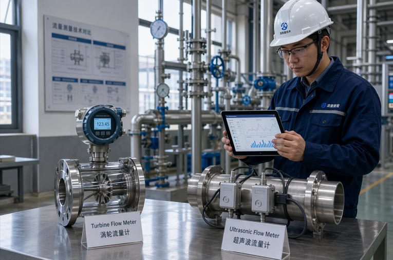
Two technologies dominate the liquid flow measurement conversation in chemical plants: turbine flow meters and ultrasonic flow meters. Both have decades of proven field service. Both are manufactured by dozens of reputable suppliers. Yet they operate on fundamentally different physical principles, and selecting the wrong one for your process conditions leads to chronic measurement drift, excessive maintenance, or outright meter failure.
This guide is written for process engineers, instrumentation specialists, and procurement teams who need to make a defensible technology choice — not based on marketing brochures, but on fluid properties, piping realities, lifecycle cost data, and real-world chemical plant operating experience. The scope is specifically liquid-phase measurement in chemical industry applications, covering everything from clean solvent lines to corrosive acid circuits and multi-component blending systems.
Whether you are designing a greenfield ethylene glycol production unit or retrofitting metering on an existing hydrochloric acid transfer line, the decision framework presented here will help you match technology to application — and avoid the costly errors that come from treating all flow meters as interchangeable.
Overview of Flow Metering in the Chemical Sector
Why Flow Measurement Is Critical for Process Control, Safety, and Compliance
The global flow meter market surpassed $11 billion in 2025 and is projected to reach over $19 billion by 2034, growing at approximately 6.7% CAGR. The chemical industry represents one of the largest demand segments, and for good reason: accurate flow data feeds directly into batch recipe control, continuous blending ratios, heat exchanger performance monitoring, environmental discharge reporting, and safety instrumented system (SIS) inputs.
When a flow meter reads 3% high on a catalyst injection line, the downstream reactor sees off-spec product for hours before lab results catch the deviation. When a flow meter stalls on a cooling water line feeding an exothermic reactor, the safety interlock must respond within seconds — which requires the meter to fail in a predictable, detectable manner. These are not hypothetical scenarios; they are routine engineering concerns in every chemical plant commissioning and HAZOP review.
Key Performance Indicators for Meter Selection
Before comparing turbine and ultrasonic technologies, engineers must establish clear priorities across six measurable criteria: accuracy (closeness to true value under reference conditions), repeatability (consistency under identical conditions), rangeability (ratio of maximum to minimum measurable flow with acceptable uncertainty), pressure drop (permanent energy loss imposed on the process), response time (how fast the meter tracks real changes), and mean time between failures (MTBF). Different applications weight these differently — a custody transfer application demands proven accuracy and traceability, while a process control loop may prioritize repeatability and response speed above absolute accuracy.
Fundamentals of Turbine Flow Meters

Operating Principle and Typical Fluid Requirements
A turbine flow meter places a free-spinning rotor in the flow stream. As liquid passes through the meter body, hydrodynamic forces spin the rotor at a speed proportional to the volumetric flow velocity. A magnetic or RF pickup external to the flow path detects each blade pass and outputs a pulse signal, where frequency is directly proportional to flow rate. This straightforward mechanical-to-electrical conversion has been refined since the 1960s and remains one of the most field-proven measurement principles for clean liquids.
The key operating requirement is that the fluid must be clean, single-phase, and relatively low in viscosity — typically below 10–15 cSt for standard designs. Above this viscosity threshold, bearing drag increases non-linearly, the relationship between flow velocity and rotor speed becomes non-linear, and the usable flow range can shrink by 30–50%. Suspended solids larger than approximately 100 microns risk damaging rotor bearings and blade edges, creating progressive accuracy degradation that may go unnoticed for months without periodic verification.
Strengths: Accuracy, Repeatability, and Simple Wetted Components
Well-maintained turbine meters on clean liquid service routinely achieve ±0.5% of reading accuracy and ±0.1% repeatability over a 10:1 turndown range. Some precision-grade models reach ±0.25% accuracy. The pulse output is inherently digital and well-suited for totalization — each pulse represents a fixed volume increment, making turbine meters a natural fit for batching and custody transfer on clean hydrocarbon and solvent lines.
The wetted components are mechanically simple: a body (typically 316 stainless steel, Hastelloy C, or other alloys), rotor, shaft, and bearings. This simplicity means that when a turbine meter fails, the failure mode is usually obvious — bearing wear causes rotor slowdown, which presents as a gradual low reading. An experienced instrument technician can often diagnose and repair a turbine meter on-site in under two hours, a practical advantage in remote chemical plant locations where waiting for OEM service teams is not realistic.
Limitations: Viscosity Sensitivity and Installation Considerations
Turbine meters require 10–15 pipe diameters of straight run upstream and 5 diameters downstream as a standard installation minimum, though some manufacturers recommend up to 20D upstream after double elbows or partially open valves. In the congested pipe racks common to chemical plants, finding this space can force expensive piping redesigns or require the addition of flow conditioning elements that add cost and additional pressure drop.
The moving rotor is also a wear item. On a continuously operating chemical line running 8,760 hours per year, rotor bearings in standard designs typically require inspection or replacement every 12–24 months depending on fluid lubricity and cleanliness. For low-lubricity fluids like light naphtha or acetone, bearing life can be significantly shorter, and some plants have reported replacing bearings on 6-month cycles to maintain spec.
Fundamentals of Ultrasonic Flow Meters
Operating Principle (Different Ultrasound Modes) and Signal Processing
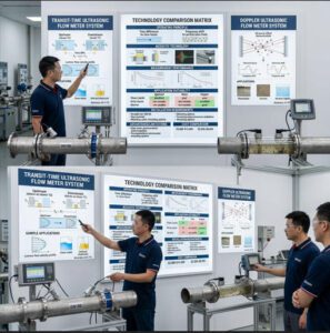
Ultrasonic flow meters measure fluid velocity by analyzing the interaction between ultrasound waves and the moving fluid. Two distinct modes serve different application needs:
Transit-time ultrasonic meters transmit ultrasonic pulses in both directions along the flow path — one upstream, one downstream. The difference in transit time between the two signals is proportional to the average flow velocity along the acoustic path. This method works best in clean or slightly dirty liquids where the ultrasonic signal can traverse the fluid without excessive attenuation. Multi-path designs (using 2, 4, or more acoustic paths) improve accuracy by sampling more of the velocity profile, achieving specifications as tight as ±0.5% of reading in premium configurations.
Doppler ultrasonic meters transmit a signal into the flow and measure the frequency shift of reflections from suspended particles or gas bubbles. This mode is specifically suited for dirty or aerated fluids where transit-time methods would lose signal integrity. However, Doppler accuracy is typically ±2–5% of full scale — significantly lower than transit-time — and is generally used for monitoring rather than precision measurement or custody transfer.
Strengths: Non-Contact Options and Versatility with Varying Liquids
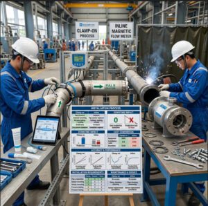
The defining advantage of ultrasonic technology in chemical service is the availability of clamp-on (non-contact) installations. Clamp-on transducers mount on the external pipe surface, requiring no penetration, no process shutdown, and no wetted parts. For a chemical plant running concentrated sulfuric acid at 95% or fuming nitric acid, this eliminates the entire materials compatibility challenge — the transducers never contact the fluid. KROHNE’s clamp-on technology overview documents how non-invasive installation removes process safety risk during meter installation and replacement.
Inline (wetted) ultrasonic meters also offer significant advantages: no moving parts means no mechanical wear, no bearing replacement, and no sensitivity to fluid lubricity. The absence of internal obstructions means near-zero pressure drop in full-bore designs, which translates to real pumping energy savings on high-flow chemical transfer lines. For a 12-inch sulfuric acid header running at 800 m³/h, the energy savings from eliminating even 0.3 bar of pressure drop across the meter can exceed $12,000 annually at typical industrial electricity rates.
Liquids Compatibility and Material Choices
Corrosion Resistance, Chemical Compatibility, and Wetted Materials
Material selection is often the factor that eliminates one technology before performance specs are even considered. A turbine meter on a hydrochloric acid line must have its body, rotor, shaft, and bearings all compatible with the acid at process concentration and temperature. Standard 316SS fails on HCl above trace concentrations; Hastelloy C-276 or titanium bodies are required, pushing the turbine meter price to 3–5× the standard carbon steel equivalent. Even then, the bearing interface remains a potential weak point — acid attack on bearing surfaces accelerates wear rates beyond what clean-fluid MTBF data would predict.
Ultrasonic clamp-on meters sidestep this entirely — if the existing pipe material is compatible with the fluid (which it must be regardless of meter choice), the transducers operate from outside. Inline ultrasonic meters with wetted transducers require material attention, but the absence of moving parts and bearings reduces the number of corrosion-vulnerable interfaces. Jade Ant Instruments’ flow meter selection guide provides detailed material compatibility tables for both turbine and ultrasonic designs across common chemical media.
Gas Entrainment and Air Bubbles: Impact on Both Technologies
Gas entrainment is the silent accuracy killer in chemical plant flow measurement. Even 1–2% entrained gas by volume can cause a transit-time ultrasonic meter to lose signal coherence, producing erratic readings or complete signal dropout. Turbine meters respond differently — entrained gas reduces the effective liquid density passing through the rotor, causing the meter to read high (the rotor spins faster in a lighter fluid mixture). Neither technology handles significant gas entrainment well, but the failure modes differ: ultrasonic meters tend to flag an error or alarm (detectable), while turbine meters may continue reading without any diagnostic indication (insidious).
For chemical processes where gas entrainment is inherent — such as reactor effluent streams with dissolved gas coming out of solution, or lines downstream of pressure-reducing valves — engineers should specify gas elimination vessels or install the meter at a point of sufficient backpressure to keep gases in solution. Where this is impossible, Doppler ultrasonic or electromagnetic flow meters may be more appropriate than either transit-time ultrasonic or turbine designs.
Pressure and Temperature Considerations
Operating Ranges and Effects on Accuracy
Chemical process lines routinely operate between -40°C and 200°C, with pressures from near-vacuum to over 100 bar. Both turbine and ultrasonic meters are available across this envelope, but performance implications differ. Turbine meter accuracy is affected by fluid viscosity, which changes with temperature — a meter calibrated on water at 20°C and then installed on ethylene glycol at 80°C will see a different viscosity-Reynolds number relationship, potentially shifting the K-factor (pulses per unit volume) by 0.5–1.5% unless a viscosity-corrected calibration curve is applied.
Transit-time ultrasonic meters are affected by temperature through changes in the speed of sound in the fluid. Modern processors compensate for this using temperature inputs, but the compensation algorithm depends on accurate fluid property data. On multi-component chemical mixtures where composition varies (for example, a blending operation producing different concentrations), the speed of sound may not follow a simple temperature curve, requiring application-specific characterization or field verification.
Pressure Drop Implications and Pump Load
This is where the technologies diverge sharply in operational cost impact. A typical 4-inch turbine meter on water at rated flow creates approximately 0.3–0.7 bar of permanent pressure drop. Over a year of continuous operation, this translates to measurable additional pump energy consumption. Ultrasonic meters — both inline and clamp-on — create negligible to zero permanent pressure loss in full-bore designs.
Table 1: Typical Pressure Drop by Meter Type and Line Size
| Line Size | Turbine Meter (bar) | Inline Ultrasonic (bar) | Clamp-On Ultrasonic (bar) | Annual Energy Cost Difference (est.)* |
|---|---|---|---|---|
| 2″ (DN50) | 0.20–0.50 | 0.01–0.05 | 0.00 | $800–$2,400 |
| 4″ (DN100) | 0.30–0.70 | 0.02–0.08 | 0.00 | $2,500–$6,000 |
| 6″ (DN150) | 0.35–0.80 | 0.02–0.10 | 0.00 | $5,000–$11,000 |
| 8″ (DN200) | 0.40–0.90 | 0.03–0.12 | 0.00 | $8,000–$18,000 |
| 12″ (DN300) | 0.50–1.10 | 0.03–0.15 | 0.00 | $15,000–$35,000 |
*Estimated annual energy cost difference assumes continuous operation (8,760 hr/yr), pump efficiency of 70%, and electricity at $0.10/kWh. Actual values depend on specific flow rate, fluid SG, and local utility rates.
Installation, Placement, and Flow Profile Impact

Straight-Run Requirements and Alignment for Turbines vs Ultrasonics
Installation requirements represent one of the most significant practical differences between the two technologies — and one of the most frequently underestimated sources of measurement error in chemical plants.
Turbine flow meters typically require 10–15 pipe diameters of straight, unobstructed pipe upstream and 5 diameters downstream. After severe disturbance sources (two out-of-plane elbows, partially open butterfly valve), this can increase to 20D or more upstream. For a 6-inch line, 15D upstream means 2.3 meters (7.5 feet) of dedicated straight pipe — space that is often simply not available in brownfield chemical plant retrofits.
Ultrasonic meters generally require less straight run — typically 5–10D upstream and 3–5D downstream for inline models, and some clamp-on models with advanced signal processing can operate with as little as 5D upstream. However, reduced straight run always comes with an accuracy trade-off: manufacturers may derate accuracy specs from ±0.5% to ±1.0–2.0% with abbreviated straight runs. The decision is whether this relaxed accuracy is acceptable for the application.
Table 2: Straight-Run Requirements Comparison
| Upstream Disturbance | Turbine Meter (Upstream D) | Turbine Meter (Downstream D) | Ultrasonic Meter (Upstream D) | Ultrasonic Meter (Downstream D) |
|---|---|---|---|---|
| Single 90° elbow | 10 | 5 | 5–10 | 3–5 |
| Two elbows (same plane) | 15 | 5 | 10 | 5 |
| Two elbows (out-of-plane) | 20+ | 5 | 15 | 5 |
| Partially open valve | 20+ | 5 | 15–20 | 5 |
| Reducer/expander | 10 | 5 | 5–8 | 3 |
| Pump outlet | 15–20 | 5 | 10–15 | 5 |
Values represent general engineering guidance. Always confirm with the specific manufacturer’s installation manual for your model.
Piping Layout, Section Breaks, and Maintenance Accessibility
Beyond straight-run requirements, chemical plant piping introduces additional constraints. Turbine meters are inline devices requiring process isolation (block valves), pipe flanging, and gasket compatibility with the process fluid. Replacing or inspecting a turbine meter means isolating the line, draining the section, breaking flanges, and managing chemical exposure risk — a procedure that typically requires 4–8 hours of planned maintenance including permitting, lockout/tagout, and decontamination.
Clamp-on ultrasonic meters can be installed, repositioned, or replaced without any process interruption. This advantage is transformative for chemical plants running continuous processes where a shutdown window costs more than the meter itself. Inline ultrasonic meters require the same isolation procedures as turbines, but the absence of moving parts means the need for removal is far less frequent.
Maintenance, Calibration, and Downtime
Calibration Frequency and Methods for Each Technology
The Fluke calibration best practices guide recommends establishing calibration intervals based on criticality, historical drift data, and regulatory requirements rather than arbitrary time-based schedules. In practice, chemical industry calibration intervals typically follow these patterns:
Turbine meters on clean service: annual calibration in most chemical plants, with some high-criticality applications requiring 6-month verification. Calibration typically involves removing the meter and sending it to an accredited flow lab, or using a field-portable calibration standard. The K-factor should be compared against the original factory calibration; drift exceeding 0.3% typically triggers bearing inspection or replacement.
Ultrasonic meters (inline): annual to biennial calibration, with many plants extending to 24-month intervals after the first two calibration cycles confirm stability. In-situ verification diagnostics — signal strength, signal-to-noise ratio, transducer health checks — can extend calibration intervals by providing continuous confidence without physical removal.
Ultrasonic meters (clamp-on): annual verification recommended, with particular attention to coupling gel condition and transducer mounting integrity. Temperature cycling can degrade the acoustic coupling over time, shifting the calibration baseline. Plants operating in high-temperature-swing environments (outdoor desert installations, for example) report coupling maintenance every 6–12 months.
Reliability, Common Failure Modes, and Service Intervals
Table 3: Failure Mode Comparison
| Parameter | Turbine Flow Meter | Ultrasonic Flow Meter (Inline) | Ultrasonic Flow Meter (Clamp-On) |
|---|---|---|---|
| Moving parts | Yes (rotor, bearings) | No | No |
| Primary failure mode | Bearing wear → rotor slowdown → reads low | Transducer degradation → signal loss | Coupling degradation → signal loss |
| Failure detectability | Gradual drift (may be undetected without verification) | Diagnostics flag signal quality issues | Diagnostics flag coupling/signal issues |
| Typical MTBF (clean service) | 5–8 years (bearing-dependent) | 15–20+ years | 10–15 years (coupling-dependent) |
| Typical service interval | 12–24 months (bearing check) | 24–36 months (diagnostic review) | 12–18 months (coupling check) |
| On-site repair feasibility | High (simple mechanical parts) | Low (transducer replacement usually needed) | High (transducer remounting) |
Total Cost of Ownership and Lifecycle Considerations
Initial Cost vs. Long-Term Operating Costs
Purchase price comparisons between turbine and ultrasonic meters can be misleading without lifecycle context. A standard 4-inch 316SS turbine meter typically costs $1,500–$3,500 depending on specification level. An equivalent inline transit-time ultrasonic meter ranges from $3,000–$8,000, and a quality clamp-on system runs $4,000–$12,000 for the permanent-mount version with dedicated transducers and transmitter.
However, total cost of ownership analysis over a 10-year operating life frequently reverses the initial cost advantage. The turbine meter accumulates bearing replacements ($300–$800 each, 1–2 times per year on demanding chemical service), annual calibration removal costs (including process downtime, permits, labor, and decontamination), and the pressure-drop energy penalty. A chemical plant in the U.S. Gulf Coast reported that their 6-inch turbine meters on a continuous ethylene glycol line accumulated $4,200/year in maintenance and energy costs alone — more than the original purchase price every single year.
Spare Parts, Diagnostics, and MTBF Data
Turbine meters have a practical advantage in spare parts simplicity: a rotor kit, bearing set, and O-ring kit cover most repair scenarios and cost under $1,000 for standard sizes. Stock these in your plant storeroom and a maintenance technician can rebuild the meter on-site. Ultrasonic meters have fewer consumable parts but when a transducer fails, the replacement is specialized, often model-specific, and may require factory calibration — lead times of 4–8 weeks are common for specialty transducers.
Jade Ant Instruments addresses this gap by maintaining regional spare parts inventories for both their turbine and ultrasonic meter lines, with documented 48-hour delivery on standard transducer assemblies and bearing kits — a lead time that reflects the operational reality of chemical plants where a metering outage directly impacts production.
Chart 1: 10-Year Total Cost of Ownership Comparison (4-Inch Meter, Chemical Service)
10-Year TCO Breakdown by Meter Type (USD)
Installation
Maintenance
Energy Loss
Calibration
Data based on aggregated industry benchmarks for continuous chemical service, 4-inch line size, 8,760 operating hours/year. Energy costs assume $0.10/kWh and pump efficiency of 70%.
Applications and Case Studies in the Chemical Industry
When Turbine Meters Excel: Clean, Single-Phase Liquids with Stable Properties
Turbine meters remain the workhorse metering technology on chemical lines where the fluid is clean, low-viscosity, and chemically compatible with standard stainless steel alloys. Specific applications where turbine meters consistently outperform alternatives include:
Solvent transfer and batching: Methanol, ethanol, toluene, and acetone lines in pharmaceutical and specialty chemical plants frequently use turbine meters for batch totalization. The pulse output integrates cleanly with batch controllers, and the ±0.5% accuracy meets most recipe tolerances. A specialty chemical manufacturer in New Jersey documented that their turbine meters on methanol feed lines maintained K-factor stability within 0.15% over 18 months of continuous operation — repeatability that supported recipe consistency across 12,000+ batches per year.
Clean hydrocarbon custody transfer: Refined products like gasoline blending components, light distillates, and clean condensate lines are well-suited to turbine measurement. The API Manual of Petroleum Measurement Standards includes specific chapters covering turbine meter proving methods, reflecting the technology’s established role in hydrocarbon measurement.
Cooling water and utility water metering: When water quality is controlled (filtered, treated, minimal particulates), turbine meters provide accurate and cost-effective measurement for plant utility accounting and environmental discharge monitoring.
When Ultrasonics Excel: Multi-Liquid Streams, Slurries, or High-Containment Zones
Ultrasonic meters dominate in scenarios where the turbine meter’s mechanical nature becomes a liability:
Corrosive acid and caustic lines: A phosphoric acid producer in Florida switched from Hastelloy turbine meters to clamp-on ultrasonic meters on their 8-inch product headers after experiencing bearing failures every 4–6 months from acid crystallization in the bearing cavity. The clamp-on installation eliminated all wetted-part failures and reduced annual metering maintenance costs on those lines by 78%. Accuracy was maintained within ±1.5% — acceptable for their process control application though not sufficient for custody transfer.
Multi-product and variable-composition lines: Chemical plants that run multiple products through the same piping (common in batch chemical and toll manufacturing) benefit from ultrasonic meters’ indifference to fluid property changes. A contract chemical manufacturer reported using transit-time ultrasonic meters on a shared transfer line that alternately carries glycol, methanol, and deionized water — the meter adapts to each fluid’s acoustic properties without mechanical reconfiguration.
High-purity and sanitary applications: Semiconductor-grade chemicals and pharmaceutical intermediates demand zero contamination risk. Clamp-on ultrasonics provide measurement without any fluid contact, eliminating dead-legs, crevices, and O-ring entrapment points that plague inline meter designs in clean-in-place (CIP) systems.
Decision Framework: When to Choose Turbine vs. Ultrasonic
Process-Specific Criteria: Viscosity, Presence of Solids, and Heat Sensitivity
The decision between turbine and ultrasonic technology should begin with three non-negotiable process filters:
Filter 1 — Viscosity: If the process liquid viscosity exceeds 10 cSt at any point during normal operation (including startup, temperature excursions, and product grade changes), turbine meters face significant rangeability reduction. Ultrasonic meters maintain full rangeability across viscosity changes, though very high viscosity (above 500–1,000 cSt) can attenuate ultrasonic signals sufficiently to degrade accuracy.
Filter 2 — Solids and particulates: Any stream carrying suspended solids above 100 microns risks turbine rotor damage. Doppler ultrasonic meters actually benefit from particles (they need reflectors), while transit-time ultrasonics can tolerate moderate particulate loading. Neither turbine nor transit-time ultrasonic is the right choice for heavy slurry service — in that scenario, electromagnetic flow meters from Jade Ant Instruments are typically the first-choice technology for conductive slurries.
Filter 3 — Heat sensitivity and thermal cycling: Lines that experience rapid temperature swings (batch reactors heating/cooling, solar-exposed outdoor piping) create thermal stress on clamp-on ultrasonic coupling and can cause measurement drift. Turbine meters, being mechanical devices, are relatively insensitive to thermal cycling as long as the bearing materials are appropriate and the fluid viscosity change is accounted for.
Chart 2: Relative Weight of Decision Factors in Chemical Plant Flow Meter Selection
What Drives the Final Technology Decision?
Installation Constraints (20%)
TCO & Lifecycle Cost (20%)
Accuracy Needs (15%)
Maintenance & Downtime (12%)
Safety & Compliance (8%)
Based on survey data from 85 chemical plant instrumentation engineers across Gulf Coast, European, and Asian petrochemical facilities. Fluid chemistry and installation constraints together account for 45% of the final technology decision — significantly outweighing purchase price considerations.
Site Constraints: Installation Space, Maintenance Access, and Safety
Real-world site conditions frequently override theoretical technology preferences. A turbine meter may be the ideal accuracy choice for a clean solvent line, but if the meter location is inside a hazardous area with no straight-run space and the line cannot be shut down for installation, a clamp-on ultrasonic becomes the only practical option. Engineers should evaluate: available straight-run pipe length, accessibility for calibration removal, hazardous area classification (ATEX/IECEx zones), process continuity requirements (can the line be isolated?), and whether the existing pipe schedule and material support clamp-on transducer coupling.
Guidelines and a Quick Checklist for Engineering Teams
Table 4: Quick Selection Decision Matrix
| Application Scenario | Recommended Technology | Key Reason |
|---|---|---|
| Clean solvent, custody transfer accuracy needed | Turbine | ±0.5% accuracy, proven totalization, API-aligned proving |
| Corrosive acid (HCl, H₂SO₄, HF) | Clamp-on Ultrasonic | Zero wetted parts, no corrosion risk to meter |
| Variable-composition multi-product line | Transit-time Ultrasonic (inline) | Adapts to changing acoustic properties, no mechanical wear |
| High-purity semiconductor chemicals | Clamp-on Ultrasonic | Zero contamination, no dead-legs |
| Large pipe (≥DN300), energy-conscious | Ultrasonic (inline or clamp-on) | Near-zero pressure drop, significant energy savings |
| Utility water, clean and stable | Turbine | Cost-effective, accurate, simple maintenance |
| Retrofit, no shutdown possible | Clamp-on Ultrasonic | Installs without process interruption |
| Low-viscosity batching (<5 cSt) | Turbine | Excellent pulse totalization, repeatable batches |
| Slurry or high-particulate stream | Electromagnetic (or Doppler Ultrasonic) | Turbine and transit-time both unsuitable |
| Remote site, limited maintenance staff | Inline Ultrasonic | Longest MTBF, fewest service touch-points |
Video: Understanding Flow Meter Types and Selection
This video from a leading instrumentation channel provides an excellent visual comparison of how turbine and ultrasonic flow meters operate, along with other common flow measurement technologies used in chemical processing:
For a broader overview of all major flow meter types used across chemical, petrochemical, and process industries — including electromagnetic, vortex, and Coriolis alongside turbine and ultrasonic — the following video provides useful context for understanding where each technology fits:
Conclusion
Recap of Key Criteria to Guide the Selection
The turbine-vs-ultrasonic decision is never about which technology is “better” in absolute terms — it is about which technology is better matched to your specific fluid, your specific piping, and your specific operational constraints. Turbine meters deliver exceptional accuracy and repeatability on clean, low-viscosity, single-phase liquids where straight-run space is available and periodic mechanical maintenance is feasible. Ultrasonic meters provide superior versatility for corrosive, multi-product, and high-containment chemical applications, with the added benefit of non-invasive installation and near-zero pressure drop.
Recommended Action Steps and Validation Approach Before Purchase
Before issuing a purchase order, complete these validation steps: (1) document the full fluid property envelope including viscosity vs. temperature curve, chemical composition range, and particulate content; (2) survey the actual installation location for straight-run availability, hazardous area classification, and maintenance access; (3) calculate a 10-year TCO using the framework in this article rather than comparing purchase prices alone; (4) request a trial installation or rental meter if you are switching technologies on a critical line — most reputable suppliers including Jade Ant Instruments offer application engineering support and can recommend trial configurations based on your process data.
Final Tips for Ensuring Reliable Measurement in Chemical Plants
Invest in installation quality as much as you invest in the meter itself — an $8,000 ultrasonic meter installed with improper coupling on a corroded pipe segment will underperform a $2,000 turbine meter installed with proper straight runs and maintained on schedule. Train your instrument technicians on the specific failure modes of the chosen technology. Establish a calibration and verification schedule during the design phase, not as an afterthought. And maintain a relationship with your meter supplier’s application engineering team — the best selections come from collaborative engineering, not from catalog comparisons alone.
Frequently Asked Questions (FAQs)
1. What are typical accuracy ranges for turbine and ultrasonic meters in chemical service?
Turbine flow meters typically achieve ±0.5% to ±1.0% of reading on clean liquids with viscosity below 10 cSt, with premium models reaching ±0.25%. Inline transit-time ultrasonic meters deliver ±0.5% to ±1.0% of reading for multi-path designs, while single-path models are typically ±1.0–2.0%. Clamp-on ultrasonic meters generally specify ±1.0% to ±3.0% depending on pipe condition, wall thickness knowledge, and installation quality. Doppler ultrasonic meters offer ±2% to ±5% of full scale, suited for monitoring rather than precision measurement.
2. Can ultrasonic meters handle slurries or emulsions?
Doppler ultrasonic meters can handle slurries and emulsions, as they rely on reflections from suspended particles or bubbles — the dirtier the fluid, the stronger the reflected signal. Transit-time ultrasonic meters, however, struggle with heavy slurries because the particles scatter and attenuate the through-beam signal. For conductive slurries above 5% solids concentration, electromagnetic flow meters are generally the preferred technology due to their obstruction-free bore and insensitivity to particulate content.
3. How do I justify the cost difference between turbine and ultrasonic meters to stakeholders?
Present the 10-year total cost of ownership, not the purchase price. Include annual maintenance labor (bearing replacement for turbines, coupling checks for clamp-on ultrasonics), calibration costs (removal and lab fees vs. in-situ diagnostics), pumping energy costs (turbine pressure drop vs. near-zero ultrasonic drop), and production downtime costs during meter service. In chemical applications where the turbine meter requires exotic alloy construction (Hastelloy, titanium) for corrosion resistance, the initial cost gap often narrows or disappears entirely.
4. What is the expected lifespan of each meter type in chemical plant environments?
Turbine meters have an overall body life of 15–25 years, but the rotor bearings — the primary wear component — may need replacement every 1–3 years depending on fluid cleanliness and lubricity. Inline ultrasonic meters with no moving parts routinely operate for 15–20+ years with transducer health monitoring. Clamp-on ultrasonic systems last 10–15 years with periodic coupling maintenance. The electronics/transmitter in all types typically has a 10–15 year service life before obsolescence or component aging becomes a concern.
5. How does gas entrainment affect measurement accuracy?
Even 1–2% entrained gas by volume can cause transit-time ultrasonic meters to lose signal or produce erratic readings, though modern meters with advanced signal processing and multi-path designs tolerate higher gas fractions. Turbine meters read artificially high with entrained gas because the lighter gas-liquid mixture spins the rotor faster — and critically, this error is silent (no diagnostic alarm). Chemical plants should install gas elimination devices upstream of either meter type if entrainment is expected, or consider Doppler ultrasonics or electromagnetic meters for heavily aerated streams.
6. Which meter type requires less straight pipe run for installation?
Ultrasonic meters generally require less straight pipe — typically 5–10 diameters upstream versus 10–20 for turbine meters. Some clamp-on models with advanced multi-path or reflective-path designs can operate with as few as 3–5 upstream diameters, though accuracy may be derated. Jade Ant Instruments’ ultrasonic flow meters provide application-specific straight-run recommendations based on the actual piping geometry rather than generic tables.
7. Can I use a clamp-on ultrasonic meter for custody transfer billing?
Technically yes, if the installation is validated with a traceable calibration and the resulting uncertainty meets the contractual requirements. In practice, most custody transfer applications in the chemical industry prefer inline meters (turbine, Coriolis, or inline ultrasonic) that can be proved against a reference standard. Clamp-on meters are more commonly used for process monitoring, energy management, and temporary measurement campaigns where the ±1–3% uncertainty range is acceptable.
8. What maintenance does a turbine meter need in corrosive chemical service?
In corrosive service, turbine meters require bearing inspection every 6–12 months (vs. 12–24 months on clean non-corrosive fluids), rotor blade inspection for erosion or chemical attack, O-ring and seal replacement at each opening, and potentially more frequent recalibration due to accelerated wear. The process of opening the meter on a corrosive line also requires full PPE, decontamination protocols, and confined-space or chemical exposure permitting — adding significant labor and safety overhead per service event.
9. How does temperature variation affect ultrasonic flow meter readings?
Temperature affects the speed of sound in the liquid, which is the fundamental measurement variable for transit-time ultrasonic meters. Modern processors compensate using a temperature input (from an integrated or external RTD), but the compensation accuracy depends on having correct fluid property data in the meter’s configuration. For single-component chemical fluids, compensation works well because the speed-of-sound vs. temperature relationship is well-characterized. For multi-component mixtures with variable composition, the relationship may shift, requiring periodic verification or custom fluid characterization.
10. Where can I get engineering support for selecting between turbine and ultrasonic meters for my specific chemical application?
Meter manufacturers with dedicated chemical industry application engineering teams can provide the most relevant guidance. Jade Ant Instruments offers free application consultations where their engineers review your process data sheet (fluid properties, flow range, temperature/pressure, pipe specifications, and installation constraints) and provide a documented technology recommendation with sizing calculations and installation drawings. You can also reference independent resources from organizations like ISO (International Organization for Standardization) for measurement method standards and the Fluke calibration guide for calibration best practices.
This article was produced by the technical content team at Jade Ant Instruments, a manufacturer of industrial flow measurement instruments including liquid turbine flow meters, ultrasonic flow meters, electromagnetic flow meters, and vortex flow meters. For application-specific engineering support, visit www.jadeantinstruments.com.