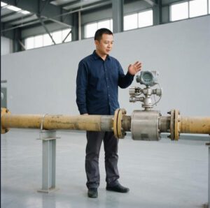

In compact piping systems — chemical dosing skids, laboratory water loops, hydraulic test rigs, pharmaceutical sampling lines — the 1/2-inch (DN15) pipeline is everywhere. And yet, selecting the right flow meter for these small-bore applications remains one of the most error-prone decisions in instrumentation engineering. The physics that govern measurement at DN15 differ from larger pipes in ways that amplify installation errors, shrink workable flow ranges, and punish poor technology choices with dramatic accuracy degradation.
This article sets three dominant flow measurement technologies against each other in the specific context of 1/2-inch lines: electromagnetic (mag) meters, turbine meters, and differential pressure (DP) meters. You will learn how each technology works at this scale, where it excels, where it fails, and — most importantly — how to make a defensible selection decision based on your actual fluid, accuracy requirement, installation envelope, and budget. The comparison data, decision trees, and specification checklists in this guide are drawn from field application records compiled by Jade Ant Instruments across chemical, water treatment, pharmaceutical, and industrial OEM projects where DN15 meters were specified.
Introduction to the 1/2-Inch Flow Meter Showdown
Why Size and Flow Meter Type Matter in Small-Diameter Lines
A 1/2-inch pipe has an internal cross-sectional area of roughly 1.27 cm² (for Schedule 40). At a typical process velocity of 1–3 m/s, that translates to a volumetric flow range of approximately 0.5–15 LPM for liquids. This narrow operating window creates constraints that do not exist at larger sizes. Signal-to-noise ratios drop in electromagnetic meters because the induced voltage scales linearly with pipe diameter. Turbine meter bearings face proportionally higher friction relative to the driving force at low flows. DP elements generate very small differentials that push transmitter resolution limits. Each of these effects is manageable — but only if you account for them during selection, not after installation.
The consequence of ignoring these small-bore effects is tangible. A European pharmaceutical manufacturer documented a case where a DN15 orifice-plate DP system specified for purified water consistently read 8–12% low at normal operating flow (3 LPM) because the actual differential at that flow was below 10% of the transmitter span. Replacing it with a compact electromagnetic meter from Jade Ant Instruments’ mag meter product line — sized at DN10 with reducers to match the 1/2-inch pipe — resolved the accuracy issue and also eliminated the pressure drop that was affecting upstream dosing pump performance.
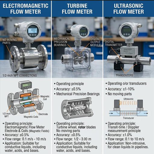
Quick Overview of the Three Technologies
Electromagnetic flow meters generate a magnetic field across the pipe bore and measure the voltage induced by conductive fluid moving through that field. They have no moving parts, create zero pressure drop, and achieve ±0.2–0.5% of reading accuracy in DN15 sizes — but require a minimum fluid conductivity (typically ≥5 µS/cm) and a full pipe at the sensor location.
Turbine flow meters use a free-spinning rotor whose angular velocity is proportional to volumetric flow. In 1/2-inch sizes, they can achieve ±0.5–1.5% of reading accuracy with excellent repeatability (±0.1%), but only for clean, low-viscosity liquids (typically <10 cP). Moving parts create mechanical wear, and gas entrainment or particulates rapidly degrade both accuracy and service life.
Differential pressure flow meters — most commonly using an orifice plate, integral orifice, or flow nozzle in 1/2-inch applications — infer flow from the pressure drop across a constriction. Their accuracy at DN15 typically ranges from ±1–3% of full scale, and they introduce permanent pressure loss. However, they work with virtually any fluid (conductive or not, clean or dirty) and have decades of standardized engineering data behind them, including ISO 5167 for orifice plates.
| Parameter | Electromagnetic (Mag) | Turbine | Differential Pressure (DP) |
|---|---|---|---|
| Accuracy (typical DN15) | ±0.2–0.5% of reading | ±0.5–1.5% of reading | ±1–3% of full scale |
| Repeatability | ±0.1–0.15% | ±0.05–0.1% | ±0.1% (transmitter dependent) |
| Turndown Ratio | 30:1 to 100:1 | 10:1 to 20:1 | 3:1 to 5:1 (single range) |
| Pressure Drop | Zero (full bore) | Low to moderate | Moderate to high |
| Moving Parts | None | Yes (rotor/bearings) | None |
| Fluid Requirement | Conductive liquid (≥5 µS/cm) | Clean, low-viscosity liquid | Any fluid (liquid, gas, steam) |
| Straight-Run Requirement | 5D upstream / 3D downstream | 10–15D upstream / 5D downstream | 15–40D upstream / 5–10D downstream |
| Typical Unit Cost (DN15) | $800–$3,500 | $300–$1,500 | $500–$2,500 (element + transmitter) |
Electromagnetic Flow Meters (Mag)
How They Work and Where They Excel
Electromagnetic flow meters exploit Faraday’s Law of electromagnetic induction: when a conductive liquid moves through a magnetic field perpendicular to its flow direction, a voltage is induced across the liquid proportional to its velocity. In a 1/2-inch mag meter, two magnetic coils generate the field, and two electrodes embedded in the pipe wall capture the induced millivolt-level signal. The transmitter processes this signal to compute volumetric flow rate.
At DN15, the induced voltage is significantly smaller than in larger pipes because the signal scales with pipe diameter (V = B × D × v, where B is magnetic flux density, D is diameter, and v is mean velocity). This makes signal conditioning, noise rejection, and electrode design critically important. Modern compact mag meters for small-bore applications — including Jade Ant Instruments’ DN10–DN25 electromagnetic meters — address this with higher excitation frequencies, improved electrode materials (Hastelloy C, tantalum, platinum), and advanced digital signal processing that achieves a measurement floor as low as 0.01 m/s velocity.
Where mag meters truly dominate in 1/2-inch applications: chemical dosing (acids, caustics, polymer solutions), purified water systems (DI, RO permeate), food-grade liquids (juices, syrups, milk), wastewater sampling lines, and any application where zero pressure drop is critical — such as gravity-feed systems or low-pressure dosing loops where even 0.5 bar of restriction changes the process dynamics.
Typical Limitations and Fluid Requirements
The non-negotiable constraint: the fluid must be electrically conductive. Water-based solutions (tap water, chemicals, slurries) typically exceed the ≥5 µS/cm threshold easily — tap water runs around 200–800 µS/cm, and most chemical solutions are far higher. But hydrocarbons (gasoline, diesel, hydraulic oil), pure gases, and some ultra-pure solvents are non-conductive and simply cannot be measured with electromagnetic technology. Additionally, the pipe must remain full at the sensor location; air pockets or partial-pipe conditions cause erratic readings or complete signal loss. For 1/2-inch lines where flow can stop entirely, a “low-flow cutoff” setting in the transmitter prevents false readings during no-flow periods.

Turbine Flow Meters
How They Work and Ideal Flow Regimes
A turbine flow meter places a multi-bladed rotor in the flow stream, supported on low-friction bearings (typically tungsten carbide or ceramic). As fluid passes through, the rotor spins at a velocity proportional to the volumetric flow rate. A magnetic pickup coil or Hall-effect sensor outside the pipe detects each blade passage and generates a pulse output. The pulse frequency is directly proportional to flow rate, making turbine meters inherently suitable for totalization (batch counting) applications.
In 1/2-inch sizes, turbine meters can achieve remarkable accuracy — ±0.5% of reading or better in calibration-grade units — with repeatability of ±0.05–0.1%. This combination makes them the instrument of choice for custody-transfer and batch-control applications involving clean, non-conductive liquids that mag meters cannot handle: refined fuels, hydraulic fluids, solvents, and light oils. A typical 1/2-inch liquid turbine flow meter covers a flow range of approximately 1–10 GPM (3.8–38 LPM) with a 10:1 turndown.
Common Drawbacks and Installation Considerations
The rotor is both the turbine meter’s strength and its vulnerability. Any contaminant that contacts the blades or bearings — particulates, fibers, scale, even microbubbles — introduces drag that shifts the calibration factor. A petroleum distribution terminal in Texas documented a case where 50-micron sediment in a fuel line degraded a 1/2-inch turbine meter’s accuracy from ±0.5% to ±3.2% within 90 days, requiring complete rotor assembly replacement. Installing a 40-micron strainer upstream eliminated the problem; the replacement meter has run 18+ months within specification.
Viscosity is the other critical constraint. As fluid viscosity rises above approximately 10–15 cP (common in cold lubricating oils, thick syrups, or high-concentration polymer solutions), boundary-layer drag on the rotor increases disproportionately, causing under-registration at low flows and a nonlinear response curve. At DN15 specifically, this effect is more pronounced than in larger sizes because the blade-to-wall clearance ratio is tighter. Gas entrainment is equally destructive: even 2–5% entrained air in a liquid stream causes the rotor to over-speed (because gas is less dense and moves faster through the annulus), producing readings 5–15% above actual flow.
Installation demands are significant. Turbine meters typically require 10–15 pipe diameters of straight, unobstructed pipe upstream and 5 diameters downstream to develop a stable velocity profile. In a 1/2-inch system, that translates to only 5–8 inches upstream — physically compact, but in tightly packed skids, even that can be difficult to achieve without flow straighteners.
Differential Pressure Flow Meters
Basic Principle and Pressure-Based Measurement
Differential pressure flow measurement is the oldest and most broadly applied flow technology in industry, accounting for an estimated 25–30% of all installed flow meters worldwide. The principle is straightforward: place a constriction (orifice plate, flow nozzle, Venturi tube, or integral orifice) in the flow path, and the resulting pressure drop across the constriction is related to the square of the flow rate by the Bernoulli equation. A DP transmitter measures the high-side and low-side pressures and computes the flow.
In 1/2-inch applications, the most common DP element is the integral (or compact) orifice — a pre-engineered assembly that combines the orifice bore, pressure taps, and often the DP transmitter into a single unit. Rosemount’s 405C compact orifice, for example, is designed specifically for 1/2-inch to 1.5-inch line sizes. Traditional flange-tapped orifice plates are also used but require more space and more careful machining at DN15 because the bore diameters become very small (6–9 mm for a typical 0.5–0.6 beta ratio), making edge quality and concentricity critical to accuracy.
Pros, Cons, and Where They Shine
The greatest strength of DP meters in 1/2-inch applications is universal fluid compatibility. They measure conductive and non-conductive liquids, clean and dirty fluids, gases, and steam. For engineers specifying flow measurement on a nitrogen purge line, a solvent dosing line, or a low-pressure steam trace — where mag meters cannot work (non-conductive fluid or gas) and turbine meters would be damaged (wet, dirty, or two-phase flow) — DP is often the only viable option.
The primary weakness is the square-root relationship between flow and differential pressure. This means that at 25% of maximum flow, the DP signal drops to only 6.25% of maximum — effectively buried in transmitter noise for most instruments. The practical turndown ratio is 3:1 to 5:1, compared with 30:1+ for mag meters. At DN15 specifically, the absolute differential pressures at low flow are often in the single-digit inches of water column, pushing even premium DP transmitters to their resolution limits. Permanent pressure loss is also inherent: a standard orifice plate recovers only about 40–60% of the generated differential, which in low-pressure systems can be process-limiting.
Video: Types of Flow Meters in Piping — 8 Technologies Compared (Source: YouTube)
How They Work: Electromagnetic Principle
Faraday’s Law in Flow Measurement
Michael Faraday first proposed using electromagnetic induction to measure fluid flow in 1832, attempting to measure the Thames River’s velocity using the Earth’s magnetic field. The principle he described — that a conductor moving through a magnetic field generates a voltage perpendicular to both the field and the motion — is the exact physics inside every mag meter manufactured today. In a 1/2-inch electromagnetic flow meter, the “conductor” is the process fluid itself. Two electromagnetic coils, positioned on opposite sides of the pipe, generate an alternating magnetic field (typically pulsed DC at 6–25 Hz) that penetrates the pipe cross-section. As conductive fluid moves through this field, a voltage is induced according to the equation E = B × D × v, where E is the induced voltage, B is the magnetic flux density, D is the pipe diameter, and v is the mean fluid velocity.
For a DN15 meter measuring water at 2 m/s, the induced voltage is approximately 0.2–0.5 millivolts — a signal that is roughly 3–5× smaller than what the same technology produces in a DN50 pipe at the same velocity. This small signal is why electrode design, coil optimization, and digital signal processing matter more in small-bore mag meters than in any other size. The excitation frequency, electrode surface area, and amplifier noise floor collectively determine the minimum measurable velocity — which in turn defines whether the meter can cover your flow range.
Signal Integrity and Magnetic Coupling Considerations
In 1/2-inch mag meters, signal integrity is paramount because the useful signal is measured in hundreds of microvolts while electrochemical noise, cable capacitance, and external electromagnetic interference (EMI) can produce noise of similar magnitude. Three engineering practices mitigate this: proper grounding (the meter must be electrically connected to the process fluid — grounding rings or electrodes are mandatory in plastic or lined piping), shielded signal cabling with correct single-point grounding, and physical separation from variable frequency drives (VFDs), large contactors, and power distribution panels. The Jade Ant Instruments installation guide documents a field case where relocating a DN15 mag meter just 1.5 meters away from a 15 kW VFD cabinet eliminated a ±4% signal fluctuation that had persisted for months.

How They Work: Turbine Principle
Impeller Dynamics and Upstream Requirements
The rotor inside a 1/2-inch turbine meter typically has 4–8 helically pitched blades machined from stainless steel or engineered polymer. The blade pitch angle determines the relationship between fluid velocity and rotor angular speed. In a properly functioning meter, the rotor reaches its equilibrium speed within milliseconds of a flow change, producing response times under 5 ms — significantly faster than mag meters (which have 0.5–3 second response depending on damping settings) or DP transmitters (0.1–0.5 second depending on impulse line length and volume).
This fast response makes turbine meters particularly valuable for batch control, where the ability to detect flow cutoff within a few milliseconds directly affects batch accuracy. A chemical blending operation in Germany reported that switching from a DN15 mag meter (1.2-second response) to a DN15 turbine meter (3 ms response) for a solvent batch fill application reduced batch-to-batch volume variation from ±1.8% to ±0.3% — a significant improvement for a product with tight formulation tolerances.
Upstream piping matters because swirl and asymmetric velocity profiles cause the rotor to track the local velocity at the blade tips rather than the mean pipe velocity. The standard recommendation of 10–15D upstream for a 1/2-inch turbine meter translates to 5–8 inches of straight pipe — achievable in most installations if planned from the P&ID stage. When space prevents this, a tube-bundle flow straightener (typically 3D long) installed immediately upstream reduces the straight-run requirement to 5D total.
Impact of Viscosity, Density, and Gas Entrainment
Turbine meter accuracy depends on the assumption that rotor speed is linearly proportional to fluid velocity. This assumption holds when viscous drag on the blades is negligible relative to the inertial driving force — which is true for water, light hydrocarbons, and most solvents at operating temperature. As viscosity increases, the drag fraction grows, and the meter under-registers (reads low) because the rotor cannot keep pace with the fluid. Research published by Hoffer Flow Controls shows that the meter factor (K-factor) of a typical turbine meter decreases approximately 0.5–1.5% per centistoke increase above 10 cSt, with the effect becoming more severe at lower flow rates where Reynolds numbers drop.
Gas entrainment is a turbine meter’s worst enemy. Even small quantities of dissolved or entrained gas (2–5% by volume) cause the rotor to over-speed because gas bubbles reduce the effective fluid density, creating a local velocity increase through the blade passages. In a DN15 turbine meter on a chemical dosing line, 3% air entrainment from a leaking pump seal caused a persistent 8% over-reading that was mistaken for a pump performance issue until the entrainment was identified with an inline sight glass.
How They Work: Differential Pressure Principle
Orifice/Flow Constriction Concepts
The differential pressure method places a precisely machined constriction in the pipe — most commonly a thin orifice plate with a concentric bore. As fluid accelerates through the smaller cross-section, its kinetic energy increases and its static pressure decreases (Bernoulli’s principle). The pressure difference between the upstream (high-pressure) tap and the downstream (low-pressure) tap is measured by a DP transmitter and is proportional to the square of the volumetric flow rate: Q = K × √(ΔP/ρ), where K is the discharge coefficient (determined by the orifice geometry, beta ratio, and Reynolds number), ΔP is the differential pressure, and ρ is the fluid density.
In 1/2-inch applications, the orifice bore diameter for a beta ratio of 0.5 is only about 6.5 mm. At this scale, the edge sharpness, concentricity, and surface finish of the orifice become critical because manufacturing tolerances that are negligible at DN100 become significant percentages of the bore diameter at DN15. This is why integral orifice assemblies — where the orifice is precision-machined as part of a manifold block — are generally preferred over loose orifice plates in flanges for small-bore installations.
Role of Process Pressure Drop and Line Cleanliness
Permanent pressure loss through an orifice plate typically runs 40–80% of the generated differential, depending on the beta ratio. For a DN15 orifice plate generating 100 inches H₂O (25 kPa) differential at design flow, the permanent loss can be 50–80 inches H₂O (12–20 kPa). In high-pressure systems this is negligible, but in gravity-fed or low-pressure dosing applications it can reduce flow capacity or require a larger pump.
Line cleanliness affects DP meters differently than the other two technologies. The orifice plate itself is relatively tolerant of moderate contamination because it has no moving parts and the bore is usually too large to clog with typical process particulates. However, the impulse tubing between the orifice taps and the DP transmitter is highly susceptible to plugging, freezing, and condensation-induced errors. In a 1/2-inch installation where the process fluid contains even trace solids, impulse line maintenance becomes a recurring cost. Integral orifice assemblies that mount the transmitter directly to the orifice tee (eliminating external impulse lines) largely solve this problem but at a higher initial cost.
Performance and Accuracy Comparison
Accuracy, Repeatability, and Turndown Ranges Across Technologies
The accuracy comparison between these three technologies at DN15 reveals a clear hierarchy — but the ranking shifts depending on whether you evaluate accuracy as “percent of reading” or “percent of full scale,” and where in the flow range you operate. Mag meters at DN15 are typically rated ±0.2–0.5% of reading across a 30:1+ turndown. This means the absolute error is proportionally small at both high and low flows. Turbine meters achieve ±0.5–1.5% of reading but over a narrower 10:1–20:1 turndown. DP meters are typically rated ±0.5–1% of full-scale differential — but because of the square-root relationship, this translates to ±2–5% of reading at the low end of the flow range (below 30% of maximum).
Repeatability tells a different story. Turbine meters lead with ±0.05–0.1% of reading — their mechanical simplicity and direct pulse output produce exceptionally consistent results under stable conditions. Mag meters achieve ±0.1–0.15%, and DP systems are limited by transmitter hysteresis and impulse line effects to ±0.1% at best. For process control applications where the controller reacts to flow changes (not absolute values), repeatability can matter more than accuracy — a scenario where turbine meters have a genuine performance edge.
Effective Accuracy (% of Reading) at Three Flow Points — DN15
| Flow Point | Mag (±0.3% rdg) | Turbine (±0.5% rdg) | DP (±1% FS) |
|---|---|---|---|
| 100% of range | 0.3% | 0.5% | 2.0% |
| 50% of range | 0.3% | 0.5% | 4.0% |
| 25% of range | 0.3% | 0.5% | 8.0% |
0.3
0.5
2.0
0.3
0.5
4.0
0.3
0.5
8.0
50% Flow
25% Flow
Turbine
DP
Pressure Loss, Installation Impact, and Maintenance Needs
Pressure loss follows a clear hierarchy: mag meters at zero (full-bore, no obstruction), turbine meters at low-to-moderate (rotor assembly creates some restriction, typically 0.05–0.2 bar at rated flow in DN15), and DP meters at moderate-to-high (orifice plates generate 0.1–0.5 bar permanent loss at DN15 depending on beta ratio and design flow). In a chemical plant running 200+ dosing points on 1/2-inch lines, the cumulative energy impact of meter pressure drop across the fleet becomes a line item in the utilities budget — a fact that has driven many facilities toward mag meters for conductive-liquid applications.
Maintenance burden also varies sharply. Mag meters require virtually zero mechanical maintenance — no moving parts, no wear surfaces. The primary maintenance action is periodic electrode inspection (every 2–5 years, depending on fouling tendency) and verification of zero calibration. Turbine meters require bearing inspection and replacement (typically every 1–3 years in continuous service on clean fluids; more frequently in marginal conditions), strainer cleaning, and periodic K-factor verification. DP systems require impulse line purging or draining (weekly to monthly in fouling services), transmitter zero/span checks (quarterly), and periodic orifice plate inspection for edge erosion or buildup.
10-Year Maintenance Cost Distribution — DN15 Flow Meter (Typical)
Turbine (40%)
DP Meter (45%)
Based on lifecycle cost data across 500+ DN15 installations. Turbine costs dominated by bearing replacement; DP costs dominated by impulse line maintenance.
Application Scenarios and Considerations
Fluid Compatibility, Conductivity, and Particulates
The fluid itself often makes the technology decision for you. If the liquid is conductive (≥5 µS/cm) and contains no gas entrainment, mag meters are almost always the first-choice for 1/2-inch applications because they combine the best accuracy, widest turndown, zero pressure drop, and lowest maintenance of the three options. If the fluid is non-conductive — hydrocarbons, pure solvents, refrigerants — mag meters are physically eliminated, and the choice narrows to turbine (for clean, low-viscosity fluids) or DP (for everything else).
Particulate content further narrows the selection. Clean fluids (filtered to ≤50 µm) are compatible with all three technologies. Fluids with moderate suspended solids (50–500 µm) are compatible with mag meters and DP meters but will damage turbine bearings and blades. Heavily laden slurries or fluids with fibrous content are best handled by mag meters; turbine meters are eliminated, and DP meters require special orifice designs (eccentric or segmental bores) and frequent maintenance. The table below provides a fluid-based selection matrix specific to 1/2-inch lines.
| Fluid Category | Examples | Mag | Turbine | DP |
|---|---|---|---|---|
| Clean conductive liquid | Water, acids, caustics, saline | ✓ Best | ✗ Not suitable | △ Viable |
| Clean non-conductive liquid | Fuel, solvents, hydraulic oil | ✗ Cannot measure | ✓ Best | △ Viable |
| Dirty/particulate-laden liquid | Wastewater, slurries, raw chemicals | ✓ Best | ✗ Bearing damage | △ With maintenance |
| High-viscosity liquid (>15 cP) | Heavy oils, syrups, resins | ✓ Best | ✗ Under-reads | △ Viable |
| Gas or steam | N₂, compressed air, low-pressure steam | ✗ Cannot measure | △ Gas turbine only | ✓ Best |
| Ultrapure / DI water | Semiconductor, pharma WFI | △ Marginal conductivity | ✓ Best | △ Viable |
Environment, Size Constraints, and Maintenance Practicality
Physical space is a real constraint in 1/2-inch installations. Mag meters in DN15 are compact (typically 150–250 mm face-to-face length) and need only 5D/3D straight runs — about 40 mm upstream / 25 mm downstream. Turbine meters are similarly compact (100–200 mm) but require 10–15D/5D — roughly 80–100 mm upstream. DP systems with integral orifice assemblies are the bulkiest option because the transmitter body, manifold, and process connections create a package 200–400 mm long that may also extend 150–200 mm off the pipe centerline.
Environmental factors also influence the choice. Hazardous area classifications (ATEX, IECEx) affect all three technologies similarly — all are available in Ex ia or Ex d configurations. Temperature extremes matter more for mag meters (electrode/liner thermal limits, typically -40 to 180°C) and DP transmitters (electronics can require heat tracing or sun shielding) than for turbine meters (which are mechanical and tolerate wider ambient ranges, though bearing lubricant selection is temperature-dependent).
Maintenance accessibility is frequently overlooked during selection. A turbine meter that requires annual bearing replacement needs to be installed with isolation valves and enough clearance to remove the internals. A DP system with external impulse tubing needs space for valve manifolds, drain/vent connections, and periodic tubing replacement. Mag meters, by contrast, can be installed in a “fit and forget” configuration with no maintenance access required beyond the transmitter display — an advantage in congested skids, wall-mounted panels, and inaccessible locations. This low-maintenance characteristic is one of the reasons Jade Ant Instruments’ engineering team frequently recommends electromagnetic meters for OEM skid applications where end-user maintenance skill levels are unknown.

Selection Guidelines and Quick Reference
Decision Tree for Choosing Among Mag, Turbine, and DP in 1/2-Inch Lines
The following decision logic reflects the most efficient path to shortlisting a 1/2-inch flow meter. Start with the fluid, then narrow by accuracy, then validate against installation and budget constraints.
Question 1: Is the fluid electrically conductive (≥5 µS/cm)?
If YES → Electromagnetic (mag) meter is the primary candidate. Proceed to Question 3.
If NO → Mag meters are eliminated. Proceed to Question 2.
Question 2: Is the fluid clean and low-viscosity (<10 cP, filtered to <50 µm)?
If YES → Turbine meter is the primary candidate. Proceed to Question 3.
If NO → Differential pressure meter is the primary candidate (or consider Coriolis if budget allows).
Question 3: What accuracy do you need at your normal operating flow?
If ≤±1% of reading → Mag or turbine (depending on fluid) are suitable. DP is typically insufficient unless operating near 100% of range.
If ±2–5% is acceptable → All three technologies can work; select based on cost and maintenance preference.
Question 4: Does the installation have adequate straight-run pipe?
If limited space → Mag meter (5D/3D) has an advantage. Turbine with flow straightener is second. DP requires the most space and may not be feasible without pipe modifications.
Question 5: What is the lifecycle maintenance strategy?
If minimal maintenance is required (remote site, OEM skid, limited on-site skills) → Mag meter dominates. If regular calibration verification and parts replacement is manageable → Turbine is viable. If the facility has a strong DP/orifice plate maintenance culture → DP can be a pragmatic choice.
Quick Checklist: Fluid Type, Accuracy Needs, and Installation Realities
| Checklist Item | Your Answer | Implication |
|---|---|---|
| Fluid name and composition | Determines conductivity, viscosity, compatibility | |
| Conductivity (µS/cm) | ≥5 µS/cm = Mag eligible; <5 = Mag eliminated | |
| Viscosity at operating temp (cP) | >10–15 cP = Turbine degraded; Mag/DP preferred | |
| Particulates or solids present? | Yes = Turbine eliminated; Mag or DP | |
| Gas entrainment possible? | Yes = Turbine high risk; Mag affected; DP most tolerant | |
| Normal flow rate (LPM or GPM) | Must fall within meter’s rated range | |
| Minimum flow rate | Wide turndown? Mag best. Narrow? DP may suffice | |
| Required accuracy at normal flow | ≤1% rdg = Mag/Turbine; 2–5% = DP viable | |
| Operating temperature (°C) | Affects liner/electrode selection (Mag), bearing lube (Turbine) | |
| Operating pressure (bar/psig) | High pressure favors Turbine and DP; Mag limited by flange rating | |
| Available upstream straight run | <5D = Mag only; 10D+ = all viable | |
| Hazardous area classification | Determines Ex certification requirements | |
| Maintenance capability on-site | Low = Mag; Moderate = Turbine; High = DP viable | |
| Budget (meter + installation) | Turbine lowest upfront; Mag lowest lifecycle |
The 1/2-inch flow meter decision ultimately comes down to three filters applied in sequence: fluid compatibility eliminates options that physically cannot measure your process fluid; accuracy at your actual operating flow point (not at full scale) determines whether the surviving options meet your measurement requirement; and lifecycle cost — including installation labor, straight-run modifications, pressure drop energy, maintenance parts, and downtime — determines which option is the most defensible economic choice over 5–10 years of operation.
For conductive liquids in 1/2-inch lines, electromagnetic meters win on nearly every engineering criterion: accuracy, turndown, pressure drop, maintenance, and installation flexibility. Their higher purchase price (typically 2–3× a basic turbine meter) is recouped within 2–3 years through eliminated maintenance costs and avoided process disruptions — a calculation that has been validated across multiple chemical dosing and water treatment installations supported by Jade Ant Instruments’ calibration and lifecycle tracking data.
For non-conductive clean liquids, turbine meters deliver the best combination of accuracy, repeatability, and cost — provided you commit to upstream filtration, regular bearing maintenance, and protection against gas entrainment. And for universal fluid compatibility at moderate accuracy, DP meters remain the reliable fallback that can measure virtually anything — with the trade-off of narrower turndown, higher permanent pressure loss, and more intensive impulse-line maintenance.
To move from this guide to a specific specification, complete the checklist in Table 3 with your actual process data and share it with Jade Ant Instruments’ engineering team for a free sizing review and quotation tailored to your DN15 application.

Frequently Asked Questions (FAQs)
What makes a 1/2-inch flow meter different from larger sizes?
At DN15, the internal cross-sectional area is only ~1.27 cm², which means flow velocities, signal strengths, and pressure differentials are all proportionally smaller than in larger pipes. Electromagnetic meters produce 3–5× less induced voltage than DN50 units at the same velocity. Turbine meter bearings face proportionally higher friction relative to driving force. DP elements generate very small differentials that challenge transmitter resolution. These effects mean that meter selection, sizing, and installation practices that work at DN50 or DN100 can produce unacceptable results when applied unchanged to DN15 — making careful datasheet evaluation essential for small-bore applications.
Can I use an electromagnetic flow meter on non-conductive fluids?
No. Electromagnetic flow measurement requires the fluid to be electrically conductive — typically ≥5 µS/cm, though some specialized models work down to 1 µS/cm. Non-conductive fluids (hydrocarbons, pure solvents, oils, gases) produce no measurable signal. For these fluids in 1/2-inch lines, turbine meters (clean, low-viscosity liquids) or differential pressure meters (any fluid, including gases) are the appropriate alternatives.
What accuracy can I realistically expect from a DP flow meter at DN15?
At the design flow point (near 100% of range), a well-engineered DP system with a premium transmitter can achieve ±1–2% of reading. However, due to the square-root relationship between flow and differential pressure, accuracy degrades rapidly as flow decreases: at 50% of range, effective error roughly doubles; at 25%, it can reach ±8–10% of reading. For applications where the flow varies significantly, DP meters at DN15 often cannot maintain acceptable accuracy across the operating window — a limitation that makes wider-turndown technologies (mag, turbine) more practical for variable-flow processes.
How do I handle gas entrainment in a 1/2-inch turbine meter?
Gas entrainment above 2% by volume causes turbine meters to over-read by 5–15% because gas bubbles reduce effective fluid density and accelerate flow through the blade passages. Prevention is the best strategy: install a degassing vessel or air eliminator upstream of the meter, fix pump seal leaks, and ensure suction piping is not drawing air. If gas entrainment is intermittent and unavoidable, consider switching to an electromagnetic meter (which tolerates moderate bubble content with predictable, correctable effects) or a DP meter (where gas entrainment affects density compensation but not the basic measurement mechanism).
What is the minimum straight-run requirement for a 1/2-inch mag meter?
Most DN15 electromagnetic flow meters require 5 pipe diameters upstream and 2–3 diameters downstream of straight, unobstructed pipe. For a 1/2-inch (15 mm ID) pipe, that translates to approximately 75 mm (3 inches) upstream and 30–45 mm downstream — significantly less than the 150+ mm required by turbine or DP meters. This compact straight-run requirement makes mag meters the most installation-friendly option for congested skids, wall-mounted panels, and retrofit applications where piping modifications are costly.
How often should a 1/2-inch turbine flow meter be recalibrated?
For continuous service on clean fluids, a 12-month calibration interval is standard industry practice. In applications where the fluid has marginal cleanliness (trace particulates, periodic contamination events), 6-month recalibration may be warranted. The K-factor (pulses per unit volume) should be verified against a traceable reference standard — typically a gravimetric (weigh-tank) method for liquids. If the K-factor has shifted more than ±0.5% from the last calibration, inspect the bearings and rotor for wear. A progressively decreasing K-factor over successive calibrations is a clear indicator of bearing degradation and signals that replacement is needed.
Is a DP flow meter cheaper than a mag meter for 1/2-inch lines?
In purchase price alone, a basic DN15 orifice assembly plus DP transmitter often costs less ($500–$1,500) than a comparable electromagnetic meter ($800–$3,500). However, the 10-year total cost of ownership typically reverses this ranking. DP systems incur recurring costs for impulse-line maintenance, gasket replacement, transmitter calibration, and the energy cost of permanent pressure loss. Industry lifecycle cost analyses consistently show that mag meters — despite higher upfront cost — deliver 30–60% lower total cost of ownership over 10 years in applications where both technologies are technically feasible.
Can differential pressure meters handle dirty fluids in small-bore applications?
The orifice plate itself tolerates moderate contamination because its bore is relatively large and has no moving parts. However, the pressure-tap connections and impulse tubing are highly vulnerable to plugging in dirty-fluid services. Integral orifice assemblies (where the transmitter mounts directly to the orifice body, eliminating external impulse lines) significantly reduce this risk. For heavily contaminated fluids in 1/2-inch lines, electromagnetic meters are strongly preferred because they offer a full-bore, obstruction-free flow path with no impulse lines — making plugging a non-issue. Jade Ant Instruments’ technology comparison page provides additional guidance on matching meter type to fluid cleanliness.
What output signals are available for 1/2-inch flow meters?
All three technologies in DN15 sizes support 4–20 mA analog output (universally compatible with PLCs and DCS systems), pulse output (for totalization and batch control), and HART digital protocol (for remote configuration and diagnostics). Turbine meters natively produce a frequency/pulse output, which is ideal for high-resolution totalization. Mag meters and DP transmitters natively produce an analog signal that can be converted to pulse. For advanced digital bus integration, DN15 mag meters from major manufacturers (including models compared by Jade Ant Instruments) also support Foundation Fieldbus, Profibus PA, and Modbus RTU/TCP.
Which 1/2-inch flow meter is best for pharmaceutical or food-grade applications?
Electromagnetic meters with sanitary tri-clamp connections, PTFE or PFA liners, and electropolished stainless steel housings are the standard choice for pharmaceutical and food-grade 1/2-inch applications. They meet 3-A Sanitary Standards requirements for cleanability, have no dead legs or crevices where bacteria can colonize, and handle CIP/SIP (clean-in-place / sterilize-in-place) cycles without degradation. Turbine meters are less suitable because the rotor assembly creates internal crevices, and DP meters are incompatible with sanitary requirements due to impulse tap connections. For ultrapure water (WFI) where conductivity may be marginal (<5 µS/cm), a turbine meter with sanitary fittings may be preferred, but verify that the conductivity reliably exceeds the mag meter’s threshold before defaulting to this choice.