For flow instrumentation distributors and agents, the most expensive conversation you can have is the one that happens after an installation fails. A transit-time ultrasonic meter specified on the wrong fluid doesn’t just underperform — it erodes client trust, generates return freight claims, and hands your competitor a ready-made case study. This guide equips your technical and sales teams with the fluid compatibility knowledge to get specification right the first time, every time.
Understanding Ultrasonic Technology Fundamentals
How Ultrasonic Flow Measurement Works
Ultrasonic flow meters measure fluid velocity using sound waves — specifically, by tracking how long it takes for ultrasonic pulses to travel through the fluid in opposite directions. The physics is consistent and elegant, but the practical result depends entirely on one variable that no sensor can compensate for: the acoustic properties of the fluid itself.
There are two distinct ultrasonic measurement technologies used in industrial applications, and understanding the difference is the foundation of every fluid compatibility decision you will make:
⚡ Transit-Time Technology
- Two transducers send pulses diagonally through the fluid, one downstream and one upstream
- The time difference (Δt) between the two is proportional to flow velocity
- Requires the fluid to be acoustically transparent — clean and homogeneous
- Accuracy: ±0.5% to ±1.5% in field conditions on suitable fluids
- Best for: Clean water, oils, chemicals, glycols, pharmaceutical fluids
🔄 Doppler Technology
- Emits a continuous beam and measures the frequency shift of signals reflected off particles or bubbles
- Requires suspended solids, entrained gas, or bubbles to function — the “dirt” enables measurement
- Accuracy: ±2% to ±5% depending on particle distribution
- Best for: Wastewater, slurries, mining tailings, aerated fluids
The single most common specification mistake distributors make is treating “ultrasonic flow meter” as a single product category. Transit-time and Doppler meters have opposite fluid requirements. A client’s “dirty” slurry line that fails a transit-time meter is the ideal application for a Doppler unit — and vice versa. Selling the wrong technology to the right client is still the wrong sale.
The Role of Sound Wave Transmission in Fluid Media
Sound waves don’t travel through all fluids equally. The acoustic velocity — how fast sound moves through a liquid — varies significantly by fluid type and changes with temperature. In clean water at 20°C, sound travels at approximately 1,480 m/s. In mineral oil at the same temperature, it travels at roughly 1,430 m/s. In ethanol, 1,160 m/s. In mercury, 1,450 m/s. Each of these differences affects how the meter calculates the transit-time differential and therefore the reported flow velocity.
Modern ultrasonic meters carry onboard acoustic velocity databases or require the operator to enter the known sound speed for the process fluid. An error in this parameter — for example, configuring the meter for clean water when it is actually measuring a 30% glycol mixture — introduces a systematic bias that shows up as a constant percentage offset in all readings. In a pharmaceutical blending process where ingredient ratios are measured by flow, a 3% systematic error can mean out-of-specification product on every batch.
Key Physical Properties That Impact Performance
Four fluid properties determine whether ultrasonic technology is compatible with a given application. All four should be documented before equipment is recommended:
| Fluid Property | How It Affects Measurement | Risk Level | Mitigation Strategy |
|---|---|---|---|
| Acoustic Velocity | Directly determines transit-time calculation baseline; varies by fluid type and temperature | High | Program correct fluid sound speed; use temperature compensation |
| Viscosity | High viscosity attenuates signal; changes flow profile from turbulent to laminar, introducing profile error | High above 500 cSt | Lower frequency transducers; shorter path length; verify at operating temperature |
| Particle / Solids Content | Particles scatter transit-time signal; are required for Doppler signal reflection | Critical | Select transit-time for <2% solids; Doppler for >1% solids |
| Entrained Gas / Foam | Gas bubbles scatter and attenuate ultrasonic signal severely | Critical | Install downstream of deaerators; select installation point below gas accumulation zones |
| Temperature | Changes acoustic velocity and viscosity; ~2% velocity change per 10°C in water | Moderate–High | Active temperature compensation with RTD sensor input |
| Acoustic Impedance | Mismatch between pipe wall and fluid causes signal reflection and loss | Moderate | Select appropriate transducer coupling material; use correct frequency |
| Sources: Field data aggregated from ultrasonic meter installations across chemical, water, and process industries. Risk levels reflect field failure frequency in incorrectly specified applications. | |||
Why Fluid Properties Matter for Ultrasonic Systems
A useful mental model: think of the ultrasonic meter as a precise echo-location system. Like a submarine’s sonar, it depends on the medium it operates in to behave predictably. Change the medium — introduce suspended particles, increase viscosity, add gas bubbles — and the signal path becomes unpredictable. The meter may continue outputting a number, but whether that number reflects actual flow is a separate question entirely.
Signal Attenuation and Acoustic Impedance
Acoustic impedance (Z) is the product of a fluid’s density and its sound velocity: Z = ρ × c. When the acoustic impedance of the fluid differs significantly from that of the pipe wall, ultrasonic energy reflects at the boundary rather than transmitting through it — producing weak signals, unstable readings, or complete signal loss.
Practically, this means that clamp-on meters (which must transmit through the pipe wall before entering the fluid) are more sensitive to acoustic impedance mismatches than inline wetted-transducer designs. Light hydrocarbons and some specialty chemicals with acoustic impedance very different from steel pipe wall can produce signal quality index values below the 50% threshold required for reliable measurement — a failure mode that doesn’t announce itself dramatically, but gradually degrades reading confidence over weeks or months.
Temperature Stability and Sonic Velocity Variations
Temperature is the most commonly underestimated source of measurement error in field ultrasonic installations. In water, every 10°C rise increases acoustic velocity by approximately 2%, which produces a proportional reading error without active compensation. In oils and chemicals, the temperature-velocity relationship is steeper — heavy fuel oil can exhibit a 5–8% velocity change over a 40°C operating range. Without a temperature sensor input and active compensation algorithm, a meter on a variable-temperature oil line will track temperature fluctuations as phantom flow rate changes.

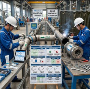
Figure 1: Commissioning a clamp-on ultrasonic meter requires verifying signal quality against the actual process fluid — not just confirming hardware connectivity. A Q-value above 60% is the threshold for reliable measurement in most industrial fluids.
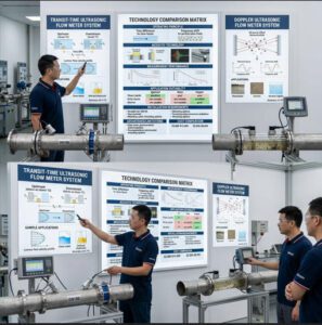
▶ Video: Doppler vs. Transit-Time ultrasonic flow meters — understanding the fundamental differences is essential for matching technology to your client’s fluid type. (~10 min, DwyerOmega)
Clean Liquids and Ideal Ultrasonic Applications
Water-Based Solutions and Their Performance Advantages
Water and water-based solutions are the reference standard against which all ultrasonic meter performance is calibrated — literally. Most factory calibration rigs use clean water at controlled temperature because its acoustic properties are precisely characterized, stable, and well-documented across the full industrial temperature range. When your client’s application involves water or a water-based fluid, you are operating in the technology’s sweet spot.
The global ultrasonic flow meter market reached USD 1.24 billion in 2025 and is projected to grow at a 6.5% CAGR through 2034 — driven substantially by water management modernization, municipal infrastructure upgrades, and industrial water efficiency programs. For distributors and agents, water applications represent the most accessible entry point for introducing clients to ultrasonic technology before expanding into more challenging fluid categories.
Potable Water and Municipal Applications
Municipal water systems represent one of the highest-volume and most technically accessible segments for ultrasonic flow measurement. Clean, treated potable water at 5–25°C produces signal quality values consistently above 80% on standard transit-time meters, delivering ±1.0% field accuracy without special configuration. The ability to install clamp-on sensors on existing DN100–DN600 distribution mains without shutting down supply — something impossible with inline insertion devices — makes retrofitting for leak detection surveys, pressure zone metering, and billing verification straightforward and fast.
A water utility in a mid-sized city that replaces 40 mechanical meter points with clamp-on ultrasonic meters can typically complete the entire project over two to three weeks of evening work — without a single service interruption, planning application, or excavation permit.
Deionized and Distilled Water in Laboratory Settings
Deionized (DI) water and distilled water are acoustically excellent fluids — clean, particle-free, and precisely characterized. However, they present a specific challenge for electromagnetic flow meters (which require fluid conductivity of at least 5 µS/cm to function) that ultrasonic technology sidesteps entirely. For semiconductor fabs, laboratory pure water systems, and pharmaceutical ultrapure water loops, ultrasonic clamp-on meters are frequently the only viable non-contact option.
On a DN300 stainless steel municipal water main at 18°C, a standard transit-time clamp-on meter installed by a trained technician in 90 minutes consistently delivers ±1.0% accuracy over a 12-month monitoring period — with zero maintenance beyond annual signal quality verification. This is the performance baseline your clients in water applications can expect.
Industrial Coolants and Process Fluids
Beyond pure water, a broad range of industrial process fluids are well-suited to ultrasonic measurement. Ethylene glycol and propylene glycol mixtures (used in HVAC and refrigeration systems) are excellent candidates — their acoustic properties are well-characterized, temperature compensation tables exist in most meter firmware, and they are clean single-phase fluids with minimal attenuation. Glycol concentrations up to 50% by volume are routinely measured with ±1.0–1.5% accuracy using standard clamp-on transit-time meters with temperature compensation active.
Oil-Based Coolants and Hydraulic Fluids
Mineral-based and synthetic hydraulic oils in the 10–100 cSt viscosity range at operating temperature are generally compatible with transit-time ultrasonic measurement. The key condition is temperature: hydraulic oils at ambient temperature (15–20°C) may have viscosities of 200–500 cSt, which is near or above the reliable measurement limit. The same oil at its operating temperature (50–70°C) may drop to 30–60 cSt, well within range. Always evaluate viscosity at the actual operating temperature — not at ambient — before confirming compatibility.
Pharmaceutical and Food-Grade Liquids
Sterile process fluids in pharmaceutical manufacturing — purified water (PW), water for injection (WFI), and saline solutions — are excellent acoustic media with the additional advantage that clamp-on measurement eliminates the dead-leg and contamination risks that any wetted inline device creates in validated systems. A major European vaccine manufacturer retrofitting clamp-on meters on 24 WFI distribution loop points avoided an estimated €180,000 in validation engineering and laboratory requalification costs by choosing non-contact measurement — costs that would have been mandatory with any inline device installation.

Figure 2: Pharmaceutical and biotechnology facilities use clamp-on ultrasonic meters on WFI and purified water loops specifically because non-contact measurement avoids the revalidation burden that any wetted inline device installation triggers.
Conductive Mediums and Specialized Fluid Categories
Conductive Liquids and Electromagnetic Interference Considerations
Conductive fluids — saltwater, electrolyte solutions, acid and alkali concentrations — present no fundamental acoustic barrier to ultrasonic measurement. The sound waves don’t care whether a fluid is electrically conductive. However, conductive fluids can create secondary issues with meter electronics if cable shielding is inadequate, and they may attack transducer housings and coupling materials if material compatibility is not verified.
This is an important differentiation to communicate to clients who are familiar with electromagnetic (mag) meters, where fluid conductivity is a prerequisite for operation. For ultrasonic technology, conductivity is irrelevant to measurement principle — which is why ultrasonic meters are the standard choice for non-conductive fluid measurement (deionized water, hydrocarbons, oils) where mag meters simply cannot function.
Saltwater and Electrolyte Solutions
Seawater and industrial brine solutions are acoustically clean and compatible with transit-time measurement. Salinity increases water’s acoustic velocity slightly (seawater at 35 PSU salinity travels at approximately 1,521 m/s versus 1,480 m/s for fresh water at 20°C) — a difference that should be entered as the correct sound speed in the meter’s configuration, or that active salinity compensation should address. The primary engineering concern for saltwater applications is material selection: standard carbon steel transducer housings corrode in saltwater service, requiring stainless steel (316L or duplex), titanium, or polymer housings depending on chloride concentration.
Acidic and Alkaline Process Fluids
Corrosive chemical fluids — hydrochloric acid, sulfuric acid, sodium hydroxide, nitric acid — are among the most compelling cases for clamp-on ultrasonic measurement. The meter’s transducers couple acoustically to the outside of the pipe and never contact the fluid, regardless of how aggressively corrosive it is. A semiconductor plant measuring 48% HF (hydrofluoric acid) flow through PVC pipe using clamp-on transducers eliminates the catastrophic leak potential that any inline wetted meter would create on this service. Three-year field data from such installations shows ±1.0–1.5% accuracy — adequate for process monitoring — with zero maintenance interventions.
For applications requiring better than ±1.0% accuracy on aggressive chemicals — batch dosing, reaction stoichiometry control — inline wetted-transducer ultrasonic meters with Hastelloy C-276, titanium, or PVDF wetted components are specified. The material selection library for ultrasonic transducers is wider than for electromagnetic electrode designs, giving distributors more configuration options for exotic chemistry service.
Slurries, Suspensions, and Particle-Laden Fluids
Particle-laden fluids define the technology boundary between transit-time and Doppler ultrasonic measurement — and this boundary is one of the most commercially important distinctions you will explain to clients.
Transit-time measurement depends on the ultrasonic signal traveling cleanly through the fluid. Suspended particles scatter and absorb that signal. Above approximately 2–3% solids by volume (roughly 20,000–30,000 mg/L), signal attenuation in a transit-time meter becomes sufficient to produce unreliable readings or complete signal loss. Below that threshold, transit-time works. Above it, Doppler is required. For borderline concentrations (1–3%), testing with the actual fluid at operating conditions is the only reliable way to confirm compatibility.
Low-Concentration Slurries (Mining and Aggregate Processing)
Mining process water and light mineral slurries with 2–10% solids by weight — such as dilute ore tailings, aggregate wash water, and sand transport flows — are the natural application zone for Doppler ultrasonic meters. Doppler meters require a minimum particle concentration (typically 75–100 mg/L of particles larger than 75 microns, or an equivalent concentration of gas bubbles) to generate a measurable reflected signal. Lightly contaminated fluids that are too dirty for transit-time but too clean for Doppler create a specification challenge; in these borderline cases, a site trial with a portable meter is the only reliable solution.
High-Concentration Suspensions and Abrasive Mediums
Dense slurries — mining tailings at 35–45% solids, paper pulp at 3–5% fibre consistency, activated sludge at 4–8% solids — push Doppler meters to their operating limits. At very high solid concentrations, the ultrasonic signal may not penetrate far enough into the fluid to measure the bulk flow velocity accurately; the meter may be measuring only the particles near the pipe wall rather than the true average velocity across the cross-section.
A practical indicator: if you can hold a glass sample of the fluid up to light and see no light transmission whatsoever, the solids concentration is likely approaching Doppler’s practical limit. For these applications, alternative technologies such as electromagnetic meters (for conductive slurries) or Coriolis meters (for high-value dense slurries requiring mass flow accuracy) should be evaluated.
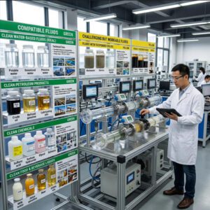
Industry-Specific Fluid Compatibility Matrix
The table below is the most directly useful reference tool in this guide — a structured compatibility matrix that your sales and technical teams can apply during client conversations and pre-sales fluid assessment sessions.
| Fluid / Application | Technology | Compatibility | Typical Accuracy | Key Consideration |
|---|---|---|---|---|
| Potable Water | Transit-Time | Excellent | ±0.5–1.0% | Ideal reference fluid; no special requirements |
| Deionized / Ultrapure Water | Transit-Time | Excellent | ±0.5–1.0% | Mag meter incompatible (non-conductive); ultrasonic only |
| Glycol Mixtures (HVAC) | Transit-Time | Excellent | ±1.0–1.5% | Program correct concentration; active temp compensation required |
| Mineral / Hydraulic Oil (<100 cSt) | Transit-Time | Very Good | ±1.0–2.0% | Evaluate at operating temperature; temp compensation essential |
| Heavy Oil / Fuel Oil (100–500 cSt) | Transit-Time (low-freq) | Limited | ±2.0–5.0% | Lower frequency transducers; test at operating temp; inline preferred |
| Bitumen / Tar (>500 cSt) | Neither | Not Recommended | N/A | Use Coriolis or positive displacement meter |
| Aqueous Acid / Alkali Solutions | Transit-Time | Very Good | ±1.0–1.5% | Clamp-on eliminates wetted-parts corrosion; verify housing material |
| Organic Solvents (ethanol, acetone, toluene) | Transit-Time | Good | ±1.0–2.0% | Program correct acoustic velocity; ATEX certification for flammable solvents |
| Seawater / Brine | Transit-Time | Good | ±1.0–1.5% | Correct salinity compensation; corrosion-resistant housing material required |
| Beverage / Juice (Low Viscosity) | Transit-Time | Very Good | ±1.0% | Sanitary requirements for inline; clamp-on for utility monitoring |
| Dairy / Milk / Emulsions | Transit-Time (low solids) | Moderate | ±1.5–2.5% | Fat content affects acoustic velocity; test before specifying |
| Municipal Wastewater (Primary) | Doppler | Very Good | ±2–3% | Minimum 25 ppm suspended solids for Doppler operation |
| Activated Sludge (2–8% solids) | Doppler | Good | ±3–5% | Clamp-on Doppler; solids concentration in acceptable range |
| Digested Sludge / Thick Sludge (>8%) | Doppler | Limited | ±5–10% | Signal penetration limited; electromagnetic often preferred |
| Mining Slurry (15–40% solids) | Doppler | Limited | ±3–5% | Test particle size distribution; clamp-on Doppler for external monitoring |
| Aerated / Foamy Fluids (>2% gas) | Neither | Not Recommended | Unreliable | Eliminate gas before measurement point; consider electromagnetic |
| Pure Light Hydrocarbons (benzene, toluene) | Transit-Time (inline preferred) | Moderate | ±1.5–3.0% | Acoustic impedance mismatch with pipe wall; inline wetted preferred |
| Biofuels (biodiesel, ethanol blends) | Transit-Time | Good | ±1.0–2.0% | Program correct acoustic velocity for blend ratio; temperature sensitive |
| Pharmaceutical PW / WFI | Transit-Time | Excellent | ±0.5–1.0% | Non-contact eliminates revalidation burden; preferred technology |
| Steam / Gas | Not Applicable | Not Suitable | N/A | Use vortex meter for steam; thermal mass for gas |
| Accuracy ranges represent field performance in typical industrial conditions. “Excellent/Very Good” assumes correct fluid acoustic velocity programmed and active temperature compensation active where required. Sources: Manufacturer field data, industry application guides, and Jade Ant Instruments industrial application data. | ||||
Scores represent typical suitability under correctly specified conditions. Field performance varies with installation quality and fluid characterization accuracy.
Chemical and Petrochemical Industries
Organic Solvents and Volatile Compounds
Common organic solvents — acetone (acoustic velocity 1,190 m/s at 20°C), ethanol (1,160 m/s), toluene (1,320 m/s) — have acoustic velocities significantly lower than water. This means the transit-time calculation gives incorrect results if the meter is configured with water’s acoustic velocity of 1,480 m/s. The error is not random; it is systematic and constant — making it easy to diagnose once suspected, but easy to miss if the meter is not verified against an independent reference after commissioning on a new fluid type.
For flammable solvent service, ATEX/IECEx Zone 1 or Zone 2 certification (or NEC Class I Div 1/2 for North American installations) must be confirmed for both the meter electronics and the transducer assembly. Clamp-on meters eliminate new pipe penetrations in the hazardous area — every pipe connection eliminated removes a potential ignition-risk leak point. This safety argument is often as persuasive to plant safety managers as the technical performance data.
Heavy Oils, Bitumen, and Viscous Hydrocarbons
Heavy fuel oil (HFO) at viscosities of 180–700 cSt is one of the most demanding applications for ultrasonic measurement. A calibration study published in 2009 — and confirmed by subsequent field data — found that ultrasonic meters on heavy fuel oil show progressive accuracy degradation as viscosity increases above 100 cSt, with measurement errors reaching ±5% or more above 300 cSt at line temperature. The root cause is dual: high attenuation of the ultrasonic signal through viscous fluid, and the transition from turbulent to laminar flow regimes at high viscosity, which introduces a velocity profile correction factor that single-path meters cannot fully compensate.
For clients with genuine HFO or bitumen applications, the honest distributor’s recommendation is to evaluate Coriolis meters (for DN15–DN150 lines where accuracy is critical) or positive displacement meters (for larger lines where cost is the primary constraint). Positioning ultrasonic as the right solution for a fluid it genuinely cannot measure reliably damages credibility far more than directing the client to an alternative technology.

Figure 3: Chemical and petrochemical plants handle dozens of different fluid types across a single facility — some ideal for ultrasonic, others requiring alternative technologies. Fluid-by-fluid assessment is the only reliable approach.
Food and Beverage Processing
Beverages, Juices, and Aqueous Solutions
Clear beverages — water, carbonated drinks (when non-aerated), fruit juices without significant pulp content, beer, wine, and spirits — are generally compatible with transit-time ultrasonic measurement. The application constraint in food and beverage is not acoustic but regulatory: inline meters must carry 3-A Sanitary Standard or EHEDG certification for direct food-contact measurement, requiring electropolished stainless steel wetted surfaces, specific surface roughness (Ra ≤ 0.8 µm), and CIP-compatible designs.
For utility monitoring — cooling water circuits, glycol chiller loops, steam condensate, and clean-in-place water — clamp-on transit-time meters have no sanitary certification requirement and are the economical default choice. Distributors serving food plant clients should maintain a clear mental map of which measurement points require sanitary inline meters versus which are utility loops where clamp-on delivers equivalent value at lower cost.
Dairy Products, Emulsions, and Viscous Food Mediums
Whole milk (~1.5–1.7% fat), cream (20–40% fat), and yogurt present a spectrum of ultrasonic compatibility challenges. Whole milk contains fat globules and protein particles that, at normal dairy processing temperatures, scatter the ultrasonic signal moderately. In practice, transit-time meters on pasteurized whole milk at 4°C show ±1.5–2.5% accuracy — workable for batch accounting but not tight enough for recipe dosing. At higher temperatures (pasteurization at 72–85°C), fat structure changes reduce scattering and improve measurement consistency.
Homogenized dairy products where fat globules are reduced to 1 µm or smaller scatter ultrasound less than non-homogenized products — a counterintuitive finding that demonstrates why empirical testing with the actual process fluid is more reliable than theoretical compatibility predictions for food emulsions.
Wastewater and Environmental Treatment
Primary and Secondary Effluent Streams
Wastewater treatment plants are among the most commercially significant application sectors for Doppler ultrasonic meters — and among the most frequently misapplied by distributors who default to transit-time specification without considering solids content.
Primary effluent (post-screening, pre-biological treatment) typically contains 150–400 mg/L of suspended solids — well above the 75 mg/L threshold for Doppler operation but often enough to compromise transit-time performance. Secondary effluent (post-biological, post-clarification) may be much cleaner, with solids below 30 mg/L — at which point a transit-time meter may outperform Doppler. The measurement point’s position in the treatment process determines which technology is appropriate. For distributors serving municipal clients, mapping the treatment flow schematic before specifying meters prevents the most common wastewater specification errors.
Sludge and High-Solids-Content Streams
Digested sludge at 2–6% dry solids and thickened sludge at 6–12% represent the upper operating range for clamp-on Doppler meters. Practical accuracy in these applications is ±5–10% — sufficient for process trend monitoring and pump performance verification, but not for billing-grade volume accounting. Electromagnetic meters, which tolerate up to 30% solids in conductive sludge, typically deliver ±0.5% accuracy on these streams and are the preferred technology for sludge handling where measurement quality matters.
The honest distributor conversation with a wastewater plant manager: “Clamp-on Doppler will tell you whether your sludge pump is running fast or slow, whether flow increased or decreased after a process change, and when a blockage is developing. If you need to know exactly how many cubic meters of sludge are being transferred to the digester for invoicing purposes, electromagnetic is the right tool.” This kind of honest, application-specific guidance builds the trust that generates repeat specification business. You can explore top applications for magnetic flow meters to understand where electromagnetic technology outperforms ultrasonic in wastewater service.
- Water & Wastewater — 35%
- Oil & Gas / Petrochemical — 20%
- Chemical & Process Industries — 15%
- HVAC & Building Systems — 13%
- Pharmaceutical & Food — 8%
- Other (Mining, Renewables, R&D) — 9%
Source: Jade Ant Instruments market analysis combined with global ultrasonic flow meter market data (FactMR, 2025). Percentages represent share of installed ultrasonic meter population by sector.
Troubleshooting Guide for Edge Cases and Problematic Fluids
Diagnosing Signal Loss and Measurement Failures
When an ultrasonic meter underperforms or fails after commissioning, the root cause is almost always one of four things: the fluid changed (composition, temperature, solids content), the pipe changed (scaling, corrosion, liner damage), the installation environment changed (vibration, EMI, temperature extremes), or the original specification was wrong. Systematic troubleshooting identifies which category the problem falls into — and whether the fix is reconfiguration, sensor repositioning, or technology replacement.
Identifying Attenuation-Related Problems
Signal attenuation — the loss of ultrasonic signal energy during transmission — manifests as declining signal quality index (Q-value) on the meter display. The diagnostic sequence:
-
Check the Q-value (signal quality index)
A Q-value below 40% indicates unreliable measurement regardless of what flow rate is displayed. Q values of 60–80%+ are required for ±1.0% accuracy. A declining Q-value from commissioning baseline indicates progressive attenuation from one of the sources below.
-
Check couplant condition
On clamp-on meters, dried, cracked, or contaminated couplant gel is the most common cause of Q-value degradation after 12–24 months. Clean the transducer face, apply fresh couplant, and recheck signal quality. If Q-value recovers, couplant was the cause.
-
Assess pipe internal condition
If couplant is intact and Q-value is still low, measure pipe wall thickness at several points using an ultrasonic thickness gauge. Scale buildup or corrosion that increases effective wall thickness attenuates the signal and shifts the acoustic path calculation. Wall thickness more than 15% above nominal indicates a significant internal condition change.
-
Verify fluid properties against meter configuration
If the fluid composition has changed — a different glycol concentration, a temperature increase changing viscosity, or a new product line running through the pipe — the meter’s acoustic velocity setting may no longer match the fluid. Recheck the configured sound speed against a reference value for the current fluid at current temperature.
-
Confirm fluid homogeneity
If solids content or gas content has increased since commissioning (a process upset, a new upstream process step, or a pump cavitation problem), the fluid may have crossed the threshold where transit-time measurement is no longer reliable. Consider Doppler evaluation or an alternative technology assessment.
Detecting Temperature-Induced Measurement Errors
Temperature-induced errors produce a characteristic signature: the flow rate reading tracks temperature changes — rising as temperature rises, falling as temperature falls — independently of actual process flow. The correlation is systematic and reproducible, distinguishing it from random noise. The fix is straightforward: enable the meter’s temperature compensation feature with a correctly installed RTD sensor providing live temperature input to the meter’s acoustic velocity correction algorithm. If temperature compensation is already active and errors persist, check that the RTD sensor is actually measuring the fluid temperature and not the ambient air temperature (a common commissioning oversight in insulated pipe installations).
Solutions for High-Viscosity and Particle-Laden Fluids
Sensor Placement Optimization and Frequency Selection
Ultrasonic transducers operate at frequencies typically ranging from 0.5 MHz (for large pipe, difficult fluid applications) to 4 MHz (for small pipe, clean fluid applications). Lower frequencies penetrate challenging fluids better — they attenuate less through viscous media, scatter less off suspended particles, and transmit more effectively through thick or rough pipe walls. The trade-off is measurement resolution: lower frequency signals are wider and less precise, limiting measurement resolution at very low flow velocities.
For clients operating at the boundary of compatible fluid conditions — moderately viscous oils (100–300 cSt), or lightly contaminated water near the transit-time/Doppler crossover point — specifying a meter with lower-frequency transducers (1–2 MHz range rather than the standard 2–4 MHz) often resolves marginal signal quality issues without requiring a technology change.
Alternative Technologies and Hybrid Measurement Approaches
When ultrasonic technology genuinely cannot meet an application’s requirements, recommending an alternative technology is the highest-value service a distributor can provide. The most common alternatives and their appropriate application zones:
🔋 Electromagnetic (Mag) Meters
- When to recommend: Conductive slurries, sludge above 8% solids, abrasive fluids, wastewater where accuracy matters
- Advantage over ultrasonic: ±0.2–0.5% accuracy on dirty conductive fluids where Doppler gives ±5%
- Limitation: Requires fluid conductivity ≥ 5 µS/cm; inline installation required
⚡ Coriolis Meters
- When to recommend: High-viscosity fluids where ultrasonic fails; mass flow required; DN15–DN150 high-value service
- Advantage over ultrasonic: ±0.1–0.2% mass flow accuracy regardless of viscosity, density, or temperature
- Limitation: High cost, significant pressure drop, limited to smaller pipe sizes economically
🔄 Vortex Meters
- When to recommend: Steam measurement (where ultrasonic is not applicable), clean gas, moderate-accuracy liquid where inline is acceptable
- Advantage over ultrasonic: Works on steam and gas without special configuration
- Limitation: Not suitable for very low velocities; inline installation required
⚙️ Positive Displacement (PD) Meters
- When to recommend: Very high-viscosity fluids (bitumen, molasses, syrup) where ultrasonic is ineffective
- Advantage over ultrasonic: Accurate measurement of extremely viscous fluids that attenuate ultrasonic signals completely
- Limitation: Moving parts require maintenance; pressure drop increases with viscosity
Managing Acoustic Impedance Mismatches
Matching Transducer Materials to Fluid Chemistry
The couplant material between a clamp-on transducer and the pipe surface, and the housing materials for both clamp-on and inline transducers, must be chemically compatible with the process environment — including ambient temperature ranges, surface condensation, and any cleaning agents used in the area. Standard petroleum-based couplant gels are not suitable above 60°C; high-temperature silicone-based gels or solid-state elastomer pads are required for hot pipe surfaces. For inline transducers in chemical service, wetted face materials include 316L stainless (general purpose), Hastelloy C-276 (HCl and mixed acid service), titanium (oxidising acid and seawater), and PVDF (caustics and fluoride service).
Calibration Strategies for Non-Standard Fluids
When a client’s fluid has no established acoustic velocity value in the meter’s internal database — a proprietary chemical mixture, a custom polymer solution, or a blend of multiple solvents — field calibration against an independent reference measurement is the most reliable approach. This involves installing the ultrasonic meter alongside a volumetric reference (a calibrated tank, a Coriolis check meter, or a certified positive displacement reference device), flowing the actual process fluid, and adjusting the meter’s acoustic velocity parameter until readings agree with the reference to within the required accuracy tolerance. This field calibration procedure should be documented and repeated annually for non-standard fluids to catch any changes in fluid composition that might shift the acoustic velocity.
Industry-Specific Application Recommendations

Figure 4: Water treatment facilities use both transit-time (for clean influent and effluent) and Doppler (for sludge and mixed liquor streams) — often within the same plant. Fluid-point mapping before equipment specification prevents costly technology mismatches.
Optimal Fluid Compatibility by Sector
Water and Wastewater: Compatibility Overview and Best Practices
Water and wastewater treatment represents the broadest and most accessible ultrasonic market for distributors — encompassing transit-time meters for clean water supply, potable water distribution, and treated effluent; and Doppler meters for activated sludge, thickened sludge, and primary effluent streams. Best practices for this sector include: always mapping measurement point position within the treatment process before specifying technology; confirming minimum solids content for Doppler meters (many secondary clarifier effluent streams are too clean for Doppler and require transit-time); and specifying IP68-rated transducer housings for submersible or outdoor installation environments.
For further reading on selecting water flow meters by application type, the Jade Ant Instruments water flow meter selection guide covers municipal, industrial, and irrigation applications with practical decision criteria.
Chemical Manufacturing: Navigating Diverse Fluid Challenges
Chemical plants are the most specification-intensive sector for ultrasonic distributors because a single facility may contain dozens of different fluid streams ranging from deionized water to concentrated sulfuric acid, from light solvents to heavy polymer solutions. The recommended approach is a process flow diagram (PFD) review for each client facility — identifying every measurement point, mapping each fluid’s key properties (viscosity, particle content, conductivity, temperature, chemical aggressiveness), and applying the compatibility matrix from Section 4 systematically.
Emerging Industries and Specialized Applications
Renewable Energy and Biofuel Production
Biodiesel, ethanol, and biogas applications are growing rapidly as an ultrasonic measurement market — driven by renewable fuel mandates, carbon credit accounting, and process efficiency monitoring. Biodiesel (fatty acid methyl esters, or FAME) has an acoustic velocity of approximately 1,380–1,420 m/s depending on feedstock — significantly lower than water but well within transit-time measurement range when the correct acoustic velocity is programmed. Ethanol-water blends used in fuel production have acoustic velocities that vary significantly with concentration (e.g., 50% ethanol-water has an acoustic velocity of approximately 1,230 m/s versus 1,480 m/s for water alone), requiring active concentration or temperature compensation.
Plant-based vegetable oils used in biodiesel production have viscosities of 30–70 cSt at processing temperatures (50–60°C) — within the reliable transit-time range. At ambient temperature (15–20°C), the same oils may be 100–300 cSt — approaching the limit of reliable ultrasonic measurement. Storage tank loading and transfer operations that occur at ambient temperature may require low-frequency transducers or alternative technology specification.
Advanced Manufacturing and Specialty Chemicals
Semiconductor, display, and advanced materials manufacturing handle proprietary chemical formulations — polishing slurries (CMP slurries at 10–30% silica or alumina content), photoresists, etchants, and developer solutions — where published acoustic velocity data rarely exists and manufacturer compatibility specifications don’t apply. In these settings, the distributor’s most valuable offering is a field trial service: deploy a portable clamp-on meter on the client’s actual process fluid at operating conditions, measure signal quality and accuracy against a volumetric reference, and document the results before committing to a permanent installation specification. This risk-free trial model converts uncertain prospects into confident buyers and positions the distributor as a technical partner rather than a product vendor.
Selection Criteria for Recommending Ultrasonic Solutions
Evaluating Client Fluid Characteristics
Every equipment recommendation should begin with a structured fluid assessment — not a product catalog review. The five-parameter fluid characterization checklist below should be completed for each measurement point before any technology is proposed:
| Parameter | Data to Collect | Disqualifying Threshold | Data Source |
|---|---|---|---|
| Fluid Type & Name | Chemical name, CAS number if available, concentration range | Unknown proprietary fluids → field trial required | Client process engineer, SDS sheet |
| Viscosity (at operating temp) | Kinematic viscosity in cSt at minimum, normal, and maximum process temperature | >500 cSt → limited compatibility; >1000 cSt → not recommended | Fluid SDS, supplier data sheet, viscometer test |
| Suspended Solids Content | % by volume or mg/L; particle size range | >2–3% vol → transit-time unreliable; >40% vol → Doppler limit | Lab analysis, client process data, visual assessment |
| Entrained Gas / Foam | Estimated % gas by volume; source of aeration | >2% entrained gas → transit-time failure; >5% → Doppler limited | Process description, client report of foam/aeration issues |
| Temperature Range | Min / normal / max operating temperature | Beyond sensor rated range → sensor damage | P&ID, client process conditions |
| Acoustic Velocity (if known) | m/s at operating temperature | Very low velocity (<700 m/s) → specialized transducer required | Meter manufacturer database, literature, field measurement |
| Use this checklist as a structured data collection tool before any equipment recommendation. Unknown values are not reasons to skip the step — they are reasons to propose a field trial before commitment. | |||
Red Flags and Disqualifying Fluid Characteristics
Several fluid characteristics are outright disqualifiers for ultrasonic technology — not limitations to work around, but fundamental incompatibilities that require honest conversation with the client. These include:
- Steam or gas phase fluids: Ultrasonic transit-time and Doppler both require liquid media. Gas-phase applications require vortex, thermal mass, or DP technology.
- Viscosity above 1,000 cSt at operating temperature: Signal attenuation is too severe for reliable measurement with any ultrasonic configuration.
- Entrained air or foam above 5% by volume: The gas phase scatters ultrasonic signals completely. No ultrasonic technology reliably measures through sustained foam.
- Multi-phase flows with changing phase ratios: Oil-water interfaces, gas slugs in liquid lines, and flashing fluids create continuously changing acoustic properties that no single calibration can accommodate.
- Non-homogeneous slurries with solids above 40% by volume: Signal penetration is insufficient for representative bulk velocity measurement.
Matching Equipment Specifications to Fluid Requirements
Frequency Selection and Transducer Design Considerations
The table below maps fluid characteristics to recommended transducer frequency ranges — a practical specification tool that bridges fluid assessment results with equipment selection:
| Fluid Category | Recommended Frequency | Pipe Diameter Range | Rationale |
|---|---|---|---|
| Clean water, DI water, glycol | 2–4 MHz | DN25–DN300 | High frequency: excellent resolution, low attenuation in clean fluid |
| Clean water — large diameter | 1–2 MHz | DN300–DN1200 | Lower frequency penetrates longer acoustic paths |
| Light oil, hydraulic fluid (10–100 cSt) | 1–2 MHz | DN50–DN400 | Moderate attenuation — mid-range frequency balances penetration and resolution |
| Heavy oil (100–500 cSt) | 0.5–1 MHz | DN80–DN300 | Low frequency essential for signal penetration through viscous media |
| Mildly contaminated water (0.5–2% solids) | 1 MHz | DN50–DN500 | Lower frequency reduces scatter loss from suspended particles |
| Wastewater / slurry — Doppler | 0.5–1 MHz | DN50–DN1000 | Low frequency + Doppler mode: maximizes particle reflection signal |
Building Client Confidence Through Expertise
Positioning Your Company as a Trusted Technical Resource
In the flow instrumentation distribution market, two types of relationships exist: transactional (the client sends an RFQ, you send a price) and advisory (the client calls you before writing the specification). Advisory relationships generate 3–5× higher margin per transaction, generate repeat business without competitive re-tendering, and survive product line changes because the value is in the expertise, not the catalog.
Fluid compatibility knowledge is one of the highest-value technical differentiators available to distributors. Most end users know what flow meter they want to buy — they don’t know whether their fluid is compatible with it. The distributor who can answer that question accurately, explain the reasoning, and recommend an alternative when needed is the distributor who gets specified before the RFQ is issued.
Teams representing Jade Ant Instruments‘ product portfolio — spanning electromagnetic, vortex, turbine, and ultrasonic technologies — are positioned to provide exactly this kind of multi-technology advisory service. When a client’s fluid disqualifies ultrasonic, recommending the right electromagnetic or vortex alternative within the same supplier relationship retains the business and deepens the advisory relationship.
Educating Clients About Fluid Compatibility and Realistic Expectations
The most common client communication failure in ultrasonic specification is over-promising accuracy on non-ideal fluids. A client told to expect ±0.5% accuracy on a glycol-water HVAC system is a satisfied client when the installed meter delivers ±1.2%. A client told to expect ±1.0% accuracy on a wastewater secondary effluent stream and receiving ±3% from a Doppler meter is a dissatisfied client — even though ±3% is technically appropriate and disclosed in the meter’s specification. The framing and expectation-setting conversation is as important as the technical selection. Document the accuracy commitment in writing for each application, tied to specific fluid conditions, before equipment is ordered.
Offering Fluid Testing and Compatibility Analysis Services
Value-added services that assess client fluids before equipment purchase remove the risk that causes clients to delay decisions or choose competitors who offer trials. A structured compatibility service offering includes: (1) fluid property data collection using the checklist in Section 7; (2) theoretical compatibility assessment using the matrix in Section 4; (3) for uncertain applications, a portable meter trial using the client’s actual fluid at operating conditions; and (4) a written compatibility report with specific equipment recommendations, accuracy expectations under stated fluid conditions, and alternative technology options if ultrasonic is not suitable.
Documentation and Technical Support for Long-Term Relationships
Creating Fluid-Specific Installation and Maintenance Guides
Each installation on a non-standard fluid should be documented with: fluid name and properties at commissioning (viscosity at operating temperature, solids content, acoustic velocity measured or calculated, temperature range), transducer type and frequency, signal quality at commissioning (Q-value baseline), acoustic velocity programmed into the meter, and temperature compensation configuration. This documentation, retained in your client records and provided to the client as a commissioning report, serves as the baseline against which future performance verification is compared. Without this baseline, distinguishing a drifting meter from a changing fluid is guesswork.
Establishing Preventive Maintenance Protocols Based on Fluid Properties
Different fluids impose different maintenance frequencies. Clean water applications in controlled environments — indoor piping, stable temperatures, no pipe scaling — can run for 2–3 years between verifications. Cooling tower water with scale-forming minerals may require signal quality checks every 6 months and couplant refresh annually. Slurry applications where the pipe interior is accumulating deposits may require transducer repositioning every 3–6 months to maintain adequate signal quality. Preventive maintenance schedules should be built into the commissioning documentation and communicated clearly to the client’s maintenance team at handover.
Practical Implementation Roadmap

Figure 5: Pre-installation fluid compatibility testing — comparing meter output against a calibrated reference at multiple flow rates — is the most reliable approach for non-standard fluids where theoretical compatibility assessment is inconclusive.
Step-by-Step Process for Assessing New Client Applications
🔧 Fluid Compatibility Decision Framework — Quick Reference
YES → Proceed to Q2
NO → Assess solids content: 1–40% → Doppler | >40% → Electromagnetic or alternative
YES → Proceed to Q3
NO → 500–1000 cSt: low-frequency transit-time (test required) | >1000 cSt: Coriolis or PD meter
YES → Proceed to Q4
NO → Deaerate before measurement point, or use electromagnetic meter
YES → Transit-Time ultrasonic is compatible — proceed to equipment specification
NO (steam) → Vortex meter | NO (gas) → Thermal mass or DP meter
Information Gathering and Preliminary Compatibility Screening
The fluid assessment checklist from Section 7 should be completed by the client’s process engineer — not estimated by the sales team. Request the fluid’s Safety Data Sheet (SDS), process operating conditions summary (temperature range, pressure range, flow range), and any available laboratory analysis data for particle content and viscosity. The SDS provides chemical identification and physical properties; the process conditions document defines the actual measurement environment. Together, these two documents enable a reliable preliminary compatibility assessment in 80–90% of applications without requiring a field visit.
Conducting Proof-of-Concept Testing and Field Trials
For the remaining 10–20% of applications where theoretical assessment is inconclusive — borderline viscosity, unusual fluid mixtures, proprietary chemical blends, or fluids near the transit-time/Doppler boundary — a portable clamp-on meter trial is the professional standard. Propose the trial as a value-added service, not as uncertainty disclosure. Frame it as: “Before we commit to a permanent installation, let’s run a three-day trial with your actual fluid at operating conditions to confirm performance and document the baseline configuration.” This approach eliminates installation failure risk, demonstrates technical competence, and builds purchase confidence.
Documentation and Knowledge Management
Creating a Fluid Compatibility Database for Your Sales Team
Every ultrasonic installation your organization completes — whether successful or not — generates valuable compatibility data. Record: fluid name and key properties, meter type and transducer frequency, signal quality at commissioning, accuracy measured against reference, any special configuration required (acoustic velocity value, temperature compensation settings), and long-term performance observations. Structured across industry sectors and fluid types, this database becomes your organization’s most defensible competitive advantage — enabling faster, more confident recommendations and fewer specification errors than any competitor who relies on catalog data alone.
Developing Technical Training Programs for Staff and Customers
Regular training on ultrasonic technology and fluid compatibility — both internal sessions for your sales and technical teams, and client-facing webinars or workshops — creates multiple commercial benefits simultaneously. It positions your organization as the technical authority in your market, equips clients to better characterize their own applications before contacting you, and reduces post-sale support calls from misapplied equipment. An annual “Fluid Compatibility Workshop” for key accounts, covering the decision framework in Section 9 with live examples from your installation database, is an investment that generates goodwill and repeat specification business in proportion to its technical quality. For broader flow meter selection principles, the flow meter manufacturer comparison resource from Jade Ant Instruments provides useful training material on technology selection across meter types.
Key Terms Glossary
Mastering Fluid Compatibility for Competitive Advantage
The fluids your clients measure define the success or failure of every ultrasonic flow meter you specify. Master fluid compatibility knowledge and you master the specification conversation — shifting from reactive price-quoter to proactive technical advisor who shapes what gets specified before the purchase order is written.
The core principles from this guide reduce to four practical actions: always characterize the fluid before recommending equipment; distinguish transit-time from Doppler by solids content and fluid cleanliness, not by brand preference; be honest about disqualifying fluid characteristics and recommend alternatives when they apply; and document every installation with commissioning data that enables long-term performance tracking and future specification confidence.
Distributors and agents who build their market position on this kind of technical depth — rather than on price alone — generate client relationships that survive product line changes, competitive undercuts, and economic cycles. The fluid knowledge you apply today is the reputation you carry into every specification conversation tomorrow. For the full range of ultrasonic and alternative flow meter solutions that support these conversations, explore Jade Ant Instruments’ product portfolio covering electromagnetic, vortex, turbine, and ultrasonic technologies across the full range of industrial fluid applications.
Frequently Asked Questions
Ultrasonic technology can measure low-to-moderate concentration slurries — typically up to 5–10% solids by volume for Doppler technology — but transit-time ultrasonic meters fail above approximately 2–3% solids. The key distinction is technology type: Doppler meters require particles or bubbles to function (they reflect the ultrasonic beam), making them specifically designed for dirty, particle-laden fluids. Transit-time meters require clean, acoustically transparent fluid and are incompatible with high-solids slurries. For dense slurries exceeding 10–15% solids by volume, electromagnetic meters (for conductive slurries), Coriolis meters (for high-value dense slurries requiring mass flow accuracy), or differential pressure methods often provide better performance. The practical field test: if you cannot see light through a glass sample of the fluid, transit-time will fail and Doppler is approaching its operational limit. Always verify solids content against manufacturer specifications for the specific Doppler meter model before committing to a specification. For a broader technology comparison, see Jade Ant Instruments’ flow meter selection framework.
Viscosity affects ultrasonic measurement through two mechanisms. First, high-viscosity fluids absorb (attenuate) ultrasonic signal energy at a higher rate than low-viscosity fluids — reducing the signal quality that reaches the receiving transducer and increasing measurement uncertainty. Second, high viscosity causes the flow regime to shift from turbulent to laminar: in laminar flow, the velocity profile is parabolic (fast in the center, slow at the walls) rather than the flatter turbulent profile that single-path transit-time meters are calibrated for. This profile change introduces a systematic bias unless the meter applies a Reynolds number-dependent profile correction. Practical guidance: below 100 cSt at operating temperature — excellent compatibility; 100–500 cSt — possible with low-frequency transducers and temperature compensation; 500–1,000 cSt — test required, inline preferred over clamp-on; above 1,000 cSt — ultrasonic is not recommended. Always evaluate viscosity at the actual operating temperature (not ambient), since oil viscosity can decrease by 70–90% between ambient and process temperature.
Acoustic impedance (Z) is the product of a fluid’s density and its acoustic velocity: Z = ρ × c. It quantifies how easily ultrasonic energy transmits between two media — specifically, between the pipe wall and the process fluid in a clamp-on installation. When two adjacent materials have very different acoustic impedance values, most of the ultrasonic energy reflects at the boundary rather than transmitting through it — like light reflecting off a glass surface rather than passing through. For most common process fluids (water, aqueous solutions, light oils), the acoustic impedance difference relative to steel pipe wall is manageable, and signal transmission is adequate. Fluids with unusually low or high acoustic impedance — some light hydrocarbons (benzene, naphtha), liquid metals, or cryogenic fluids — may produce insufficient signal transmission for clamp-on measurement and require inline wetted-transducer designs that bypass the pipe-wall transmission path entirely. Practically, acoustic impedance mismatch manifests as low signal quality (Q-value) that cannot be resolved by adjusting couplant or transducer positioning — the only solutions are switching to an inline design or to an alternative measurement technology.
Yes — with appropriate equipment selection. Ultrasonic measurement principle is not affected by fluid electrical conductivity; the acoustic signal doesn’t interact with the fluid’s electrical properties. Conductive fluids like seawater, brine, electrolyte solutions, and acid concentrations are all acoustically measurable by transit-time ultrasonic technology. The practical considerations are: (1) Housing material: saltwater and electrolyte solutions corrode standard carbon steel transducer housings; specify 316L stainless steel, duplex stainless, or titanium for chloride-containing environments. (2) Acoustic velocity: Saline solutions have slightly higher acoustic velocity than fresh water (seawater at 35 PSU ≈ 1,521 m/s vs. 1,480 m/s for fresh water at 20°C) — this difference should be entered as the correct sound speed in the meter configuration. (3) Electromagnetic interference: Highly conductive fluids in metallic pipes can create galvanic circuits that generate electrical noise; ensure adequate cable shielding and grounding. Note that while conductivity is irrelevant to ultrasonic operation, it is a prerequisite for electromagnetic (mag) meters — ultrasonic is specifically the right choice when clients ask about measuring fluids that are either non-conductive (where mag fails) or corrosively aggressive (where non-contact clamp-on ultrasonic is the safest option).
Temperature changes affect ultrasonic measurement through acoustic velocity variation — the speed of sound in a fluid changes with temperature, and since the meter calculates flow velocity from transit-time differences, an acoustic velocity change without corresponding correction produces a flow reading error. In clean water, acoustic velocity changes approximately 2% per 10°C — a meter not compensating for a 30°C temperature rise will over-read flow by approximately 6%. In oils, the temperature-velocity relationship is steeper: heavy fuel oil can exhibit a 5–8% acoustic velocity change over a 40°C range. In solvents with low boiling points (acetone, ethanol), temperature effects are compounded by density changes. The solution for any application with more than ±10°C temperature variation: active temperature compensation using an RTD (PT100 or PT1000) sensor plumbed into the fluid or mounted on the pipe surface, providing a continuous temperature input to the meter’s acoustic velocity correction algorithm. For clients in chemical processing where fluid temperature tracks reaction exotherms or ambient seasonal variation, temperature compensation is not optional — it is essential for measurement reliability. Modern meters from quality suppliers update the acoustic velocity correction continuously in real time, eliminating the need for seasonal recalibration.
Yes — several fluid categories are fundamentally incompatible with both transit-time and Doppler ultrasonic measurement. Steam and gas-phase fluids cannot be measured by liquid-phase ultrasonic meters; the acoustic properties, density, and flow physics are entirely different, requiring vortex meters, thermal mass meters, or differential pressure devices. Extremely high-viscosity fluids (bitumen at ambient temperature, heavy crude below pour point, thick polymer solutions, molasses) attenuate ultrasonic signals completely — no practically available ultrasonic frequency can penetrate these media with sufficient signal strength for measurement. Sustained foam or heavily aerated fluids with more than 5% entrained gas by volume scatter ultrasonic signals unpredictably; neither transit-time nor Doppler can measure reliably through foam layers. Non-homogeneous multi-phase flows — oil-water stratified flows, slug flows with alternating liquid and gas slugs — create continuously changing acoustic properties across the pipe cross-section that no fixed calibration can track. When clients present fluids in these categories, the honest and commercially correct response is to recommend an alternative technology — see the Technology Alternatives section for guidance — rather than attempting an ultrasonic specification that will fail in service. Transparent communication at this stage protects the installation’s success and the distributor’s long-term reputation.
Transit-time and Doppler technologies have opposite fluid requirements — a fact that generates more specification errors than any other single point of confusion in ultrasonic measurement. Transit-time meters send pulses through the fluid and require the fluid to be acoustically transparent (clean, low particle content, no significant gas). Any suspended particles or bubbles scatter the transit-time signal and degrade accuracy — above 2–3% solids by volume, transit-time measurement becomes unreliable. Doppler meters send a continuous beam and measure the frequency shift of signals reflected off particles or bubbles — they require suspended matter to function, and their accuracy actually improves (within limits) as particle concentration increases toward the measurement optimum of 2–10% solids by volume. A transit-time meter on a wastewater stream will fail or give wildly inaccurate readings. A Doppler meter on ultrapure water will give no reading at all because there is nothing to reflect the signal. The commercial implication for distributors: always determine solids content and fluid cleanliness before specifying either technology. For borderline fluids (0.5–2% solids), a portable trial is the only reliable way to determine which technology performs better on the specific fluid at the specific installation conditions. For detailed guidance, the Jade Ant Instruments transit-time comparison guide provides additional technical detail on the technology selection decision.
Ultrasonic technology is one of the best choices for corrosive fluid measurement, specifically because clamp-on configurations eliminate the wetted-parts corrosion failure modes that make conventional inline meters expensive and dangerous on aggressive chemistry service. Clamp-on transducers never contact the process fluid — they couple acoustically to the outside of the pipe, leaving all corrosion risk to the pipe itself (which is already present regardless of meter type). Hydrochloric acid at 30% concentration on a carbon steel pipe, sulfuric acid at 98% concentration in an HDPE pipe, sodium hydroxide at 50% concentration in a stainless pipe — all are measurable by clamp-on transit-time ultrasonic meters on compatible pipe materials, with zero risk of fluid exposure during installation or maintenance. The engineering checklist for corrosive fluid applications: (1) verify acoustic compatibility of the acid or alkali concentration using the meter’s fluid database or published acoustic velocity data; (2) confirm transducer housing material compatibility (316L, Hastelloy, PVDF, or titanium as appropriate for the specific chemistry and concentration); (3) verify couplant material compatibility (most gels are not resistant to acid environments — solid-state elastomer pads may be more appropriate); (4) ensure cable glands and conduit are sealed against acid vapors in the installation area. For inline designs where higher accuracy is required, wetted transducer materials must be matched to fluid chemistry — consult manufacturer material compatibility charts for each specific acid concentration and temperature.
The most reliable pre-purchase verification process follows four steps. First, complete the fluid assessment checklist: collect viscosity at operating temperature, solids content and particle size, entrained gas estimate, temperature range, and fluid chemical identity. Second, apply the compatibility matrix (Table 2 in this guide) to determine the preliminary compatibility classification for your fluid. Third, for fluids that fall into “Good” or “Limited” categories, check the meter manufacturer’s specific fluid compatibility data — most quality suppliers maintain databases of tested acoustic velocities and compatibility data for hundreds of industrial fluids. Fourth — and most importantly for uncertain applications — propose a field trial with a portable clamp-on meter on the actual process fluid at operating conditions. A three-to-five day trial with flow measured against an independent reference (a volumetric tank, a calibrated bypass meter, or correlation against a known process variable) provides definitive compatibility evidence. This trial approach eliminates the risk of purchasing equipment that underperforms on the specific fluid, and the cost of the trial is typically offset by the confidence it provides on a permanent installation decision. For complex multi-fluid facilities, the leading flow meter manufacturer comparison resource also provides guidance on when to escalate from ultrasonic to alternative technologies by fluid type and accuracy requirement.
Maintenance frequency for ultrasonic meters scales directly with fluid aggressiveness. For clamp-on meters on dirty or particle-laden fluids (wastewater, slurry, mining process water), the primary maintenance activities are: signal quality monitoring (Q-value check on the meter display, monthly for dirty fluid applications versus annually for clean water); couplant inspection and refresh (every 6–12 months for demanding environments versus 2–3 years for clean, stable installations); and accuracy verification against an independent reference (annually for most applications, more frequently in regulated environments). For inline Doppler meters on slurry applications, external pipe inspection for any deposits forming at the transducer window is recommended every 3–6 months in high-solids service. The couplant is the most frequently overlooked maintenance item — in outdoor or high-temperature installations, standard petroleum-based gel degrades within 6–12 months, and the resulting signal degradation is slow enough that it may not trigger alarms before reading errors become significant. Solid-state elastomer coupling pads, which last 3–5 years without degradation, are worth specifying for any installation where annual couplant replacement is inconvenient or costly. For applications with extreme particle content or abrasive slurries, document a quarterly signal quality log from commissioning forward — this trending data identifies degradation patterns before they become measurement failures, enabling scheduled maintenance rather than emergency response.
Dissolved gases — gases fully dissolved in the fluid at pressure, such as dissolved oxygen in water or dissolved CO₂ in carbonated beverages — do not significantly affect ultrasonic measurement when they remain in solution. The dissolved gas is part of the fluid matrix and doesn’t create acoustic discontinuities. The problem begins when dissolved gas comes out of solution and forms bubbles — typically at pressure drops, temperature increases, or turbulence downstream of restrictions. A carbonated water line measured after a pressure drop valve may be generating millions of small CO₂ bubbles that scatter the transit-time signal severely. The practical guidance: measure before the pressure drop (where gas is still dissolved) rather than after. Foam, on the other hand, is immediately problematic: a foam layer even 2–3 mm thick inside the pipe at the sensor position is sufficient to block ultrasonic signal transmission completely. Foam-generating fluids — detergents, biological broths, certain chemical reactors — should be measured at points selected specifically to avoid foam accumulation, either by pipe orientation (downward-angled pipe where foam rises away from the measurement path) or by installation point selection after a defoaming stage. If foam cannot be avoided at the measurement point, electromagnetic meters (unaffected by foam because they measure electrical conductivity rather than acoustics) are the standard alternative for conductive fluids.
Fluid chemistry affects ultrasonic sensor longevity primarily through three attack mechanisms on clamp-on installations, and more directly through wetted-material corrosion on inline designs. For clamp-on meters: (1) Chemical vapor attack on transducer housing — acid vapors, chlorine, and oxidizing chemical atmospheres can degrade standard polymer sensor housings over 12–24 months; specify IP68-rated housings with chemically resistant enclosure materials for installations in aggressive chemical atmospheres. (2) Couplant degradation — many standard couplants are not resistant to acid or solvent environments; solid-state coupling pads designed for chemical service outlast gel-type couplants by 3–5× in these conditions. (3) Cable insulation attack — chemical atmospheres that include solvents can degrade standard PVC cable insulation; specify chemical-resistant cable jackets (PTFE-insulated) for installations in solvent environments. For inline meters, wetted material selection is the dominant longevity factor: HCl service requires Hastelloy C-276; fluoride service requires titanium or PVDF; oxidizing acid service requires titanium. Mismatched wetted materials in aggressive chemistry can fail within 3–6 months. Planned replacement cycles for wetted transducers in aggressive service (typically 5–7 years in properly specified materials, versus 15+ years in clean water service) should be included in lifecycle cost modeling for inline installations on challenging chemical fluids.
Ultrasonic flow measurement is governed by a range of industry standards, though fluid compatibility per se remains application-specific. The key standards relevant to distributors and their clients include: ISO 6416:2017 — Hydrometry, measurement of discharge in open channels by ultrasonic transit-time method; ISO 17089-1 — Measurement of fluid flow in closed conduits, ultrasonic meters for gas (Part 1) and liquids (Part 2); AGA Report No. 9 — Measurement of Gas by Multipath Ultrasonic Meters (the North American standard for gas custody transfer); API MPMS Chapter 5.8 — Measurement of Liquid Hydrocarbons by Ultrasonic Flow Meters (liquid custody transfer). NIST Special Publication 250-73 defines calibration traceability for liquid flow meters in the US national measurement system. For food and pharmaceutical applications, 3-A Sanitary Standards govern inline meter hygiene requirements. None of these standards provides a definitive fluid compatibility list — they define meter performance requirements and calibration protocols for specific applications. For fluid-specific compatibility guidance, equipment manufacturer compatibility data sheets and application engineering support are the authoritative reference sources.
Specialized ultrasonic equipment for challenging fluid applications — low-frequency transducers for viscous oils, corrosion-resistant housings for chemical service, Doppler systems for slurry applications, or high-temperature transducers for hot process lines — typically costs 20–50% more than standard equipment for clean water applications. A standard clamp-on transit-time meter for DN100 water service might cost $2,500–$4,000; a low-frequency version for heavy oil service on the same pipe size might cost $3,500–$6,000. For corrosion-resistant inline designs with Hastelloy wetted components, the premium over standard 316L stainless construction is typically 40–80%. These premiums should be evaluated against the alternative costs: a mechanical meter on corrosive chemical service may require replacement every 18–24 months at $8,000–$25,000 per replacement event; a correctly specified ultrasonic meter on the same service runs for 10–15 years without wetted-part replacement. Over a 10-year horizon, the “expensive” specialized ultrasonic meter almost always has a lower total cost than a less-expensive conventional meter that requires frequent maintenance or replacement on challenging fluid service. The distributor’s role is to present this total cost argument clearly — not to compete on purchase price, but to win on lifecycle value demonstrated through concrete numbers from the client’s own operating context.
An effective fluid compatibility database for a distribution organization captures five categories of information for every completed installation: (1) Fluid identification — fluid name, chemical composition, concentration, and key physical properties at operating temperature (viscosity, density, solids content, acoustic velocity if measured); (2) Equipment specification — meter model, transducer type and frequency, clamp-on or inline configuration, pipe material and size; (3) Commissioning data — signal quality (Q-value) at installation, acoustic velocity programmed, temperature compensation settings, baseline accuracy verification result versus reference meter; (4) Industry and application context — industry sector, measurement objective, plant location; (5) Long-term performance notes — any signal quality degradation observed, maintenance interventions required, any specification lessons learned. Structure the database with fluid type and industry sector as primary sort fields so that when a new client presents a similar fluid or application, your team can immediately reference real installation data rather than relying solely on manufacturer specifications. A simple CRM tag system, a shared spreadsheet, or a structured field in your ERP system can serve this purpose — the tool matters less than the discipline of capturing and sharing the data consistently. Over three to five years, this database becomes a genuine competitive differentiator that no competitor without the same installation history can replicate, representing a compounding advantage that grows stronger as your installation portfolio expands.
Ready to Become the Ultrasonic Expert Your Clients Trust?
Jade Ant Instruments supports flow instrumentation distributors and agents with a complete portfolio of transit-time and Doppler ultrasonic meters, electromagnetic meters, vortex meters, and turbine meters — backed by ISO-certified manufacturing and application engineering expertise. Whether your client’s fluid is ultrapure pharmaceutical water or abrasive mining slurry, we provide the technology selection guidance and product range to specify the right solution for every application.
Explore Our Full Product Range View Ultrasonic Application Guide