The Complete Guide for Flow Instrumentation Distributors and Agents to Reduce Customer Complaints, Lower Support Costs, and Build Stronger Client Relationships

A properly specified flow conditioner is the difference between a meter that performs to spec from day one and a year of support calls nobody budgeted for.
Why Flow Conditioners Matter to Your Bottom Line
The Real Cost of Inaccurate Flow Measurement
A mid-sized industrial gas customer was burning through recalibration budget at twice the expected rate. Their orifice meter — a perfectly good instrument from a reputable manufacturer — was reading consistently high. Not dramatically, not visibly wrong. Just 3% high, every hour of every day.
At 500,000 m³ of gas per month, that 3% error translated into roughly $18,000 per year in billing overpayment to their gas supplier. It had been running for 26 months before anyone traced the root cause: two out-of-plane 90° elbows within 5 pipe diameters upstream of the meter. No flow conditioner. A $1,400 fix that should have been in the original installation.
That’s the real cost of inaccurate flow measurement — and it’s the cost your customers are absorbing right now, in many cases without tracking it.
Hidden expenses your customers aren’t tracking. Measurement error isn’t a one-line item in anyone’s budget. It hides inside energy bills, raw material reconciliations, batch yield reports, and regulatory compliance reviews. When a plant manager says “our meters are fine,” they usually mean “nothing has obviously broken.” The slow, persistent bias from a distorted flow profile doesn’t trigger an alarm — it just silently erodes margins.
How measurement errors compound into lost revenue. A 2% metering error on a $3M/year gas spend is $60,000 per year. Across five metering points with similar installation conditions, it’s $300,000 per year. These are real numbers from real industrial facilities — and they’re available to you as the distributor who brings the solution.
What you’ll learn in this guide. This is not a product brochure. It’s a working framework for flow instrumentation distributors and agents who want to solve their customers’ most common — and most costly — installation problems, reduce their own post-sale support burden, and build the kind of technical authority that competitors can’t undercut with a lower price.
Understanding Flow Conditioner Fundamentals
What Flow Conditioners Actually Do (Beyond the Technical Specs)
A flow conditioner (a device installed upstream of a flow meter that restructures the velocity profile of the fluid before it reaches the sensor) does one job with major consequences: it takes disordered, asymmetric, swirling flow and converts it back into the smooth, symmetric, fully developed profile that the meter was calibrated to measure.
Without this, every flow meter — no matter how precise — is measuring something different from what it was designed for.
The physics is straightforward: when a fluid passes through a pipe elbow, the flow accelerates on the outer bend and slows on the inner side. When it passes through a partially open valve, it jets through the opening and creates turbulent eddies downstream. When it passes through two elbows in perpendicular planes — a very common piping configuration — it develops swirl (a corkscrew-like rotation of the fluid), which can persist for 40–80 pipe diameters without intervention.
Most meter technologies — orifice plates, turbine meters, thermal mass sensors, single-path ultrasonics — are calibrated against a smooth, symmetric flow profile. Feed them a distorted one and they measure what they see. Not what’s actually flowing.
According to field data compiled from 1,847 service tickets by Инструменты "Нефритовый муравей, insufficient straight-run pipe — the direct cause that flow conditioners address — accounts for 28% of all post-installation accuracy complaints. That’s the single largest root cause category. Not meter defects. Not calibration errors. Upstream piping conditions.
How Flow Conditioners Solve Your Customers’ Real Problems
Eliminating measurement drift that costs your clients money. The insidious feature of profile-distortion error is that it isn’t stable. As the flow rate changes, as temperature shifts, as a control valve upstream changes position, the distortion pattern changes — and so does the error magnitude. A 3% error today may be a 1% error tomorrow and a 5% error next week. This variability is nearly impossible to correct with a simple offset factor. Conditioning removes the root cause rather than trying to compensate for it.
Reducing the velocity profile distortions that create false readings. A well-specified perforated plate conditioner can reduce swirl intensity from above 15° to below 2° within five pipe diameters downstream — meeting the <2° swirl threshold required by most ultrasonic meter installation standards (AGA-9, ISO 17089). For orifice meters under AGA-3 or ISO 5167, this transforms a non-compliant installation into a compliant one.
Protecting your reputation when installations underperform. When a meter you sold reads 4% high for a year, the customer’s first call is to you. The fact that the real problem is the piping configuration — not the meter — is cold comfort after that conversation. A pre-delivery conditioning recommendation that was declined by the customer is also cold comfort unless you documented it. The conditioner conversation protects your products, your margins, and your credibility simultaneously.
The Five Types of Flow Conditioners and When to Recommend Each
1. Straightening Tube / Tube Bundle Designs. A bundle of parallel tubes or honeycomb cells that breaks up swirl by preventing rotational flow from propagating through the channels. Best for: applications where swirl is the dominant disturbance, available space is limited, and pressure drop must be minimized. Typical pressure loss coefficient (Kp): 0.75–1.25. Limitation: effective against swirl but does not redistribute axial profile asymmetry — meaning it won’t fully solve the problem from a reducer or an out-of-plane double elbow.
2. Perforated Plate Conditioners. A precision-engineered plate with a calibrated hole pattern, creating a controlled pressure drop that simultaneously breaks swirl and redistributes the axial velocity profile. This is the dominant technology for demanding applications and compliance-critical metering. Typical Kp: 2.0–5.0. Best for: orifice and ultrasonic meter compliance installations, high-pressure gas service, applications where space can be saved by reducing required straight run. The Jade Ant Instruments Flow Conditioner Selection Guide covers the specific configurations and performance trade-offs in detail.
3. Combination / Hybrid Vane-Plate Units. A tube bundle or swirl vane placed 3–5 pipe diameters upstream of a perforated plate. The first element attacks swirl; the second handles profile redistribution. Best for: severe multi-elbow or valve-downstream scenarios where a single component cannot achieve the required performance in the available space. These have demonstrated swirl angle reduction from 25° to below 2° within 10 pipe diameters in third-party testing.
4. Swirl-Reducing Tab Designs. Insertable tabs or fins welded or bolted to the pipe interior, oriented to mechanically interrupt the rotational flow pattern. Best for: retrofit situations where the pipe cannot be cut and a spool-piece design is not feasible. Lower conditioning effectiveness than plate designs but installable with minimal shutdown time.
5. Integrated Strainer-Conditioner Designs. Combines a strainer basket for particulate removal with a conditioning plate or vane in a single spool piece. Best for: commissioning phases on new pipelines, aging systems with uncertain cleanliness, and remote metering stations where single-access-point maintenance reduces operational cost. A genuine two-for-one value proposition that you can present to cost-conscious customers without apologizing for the price.
Why Generic Installation Advice Fails Your Customers
Here is the scenario that plays out repeatedly in industrial instrumentation: an engineer reads the manufacturer’s datasheet, notes the “10D upstream / 5D downstream” straight-run requirement, confirms that the available pipe length meets this threshold, and installs the meter without conditioning. Readings drift. The investigation reveals that the “10D” requirement assumes a single in-plane elbow as the upstream disturbance — not the double out-of-plane configuration that actually exists in the field.
Manufacturer straight-run tables are derived from controlled single-disturbance lab conditions. Real-world piping has multiple disturbances in close succession, and the combined effect is not additive — it’s multiplicative. This is the gap between generic installation advice and the field reality your customers live with.
The Accuracy Problem Your Customers Face
The Hidden Accuracy Loss in Your Current Installations
Without proper flow conditioning, here is what your customers’ meters are actually delivering:
| Нарушение в верхнем течении | Unconditioned Error (Typical) | With Quality Conditioner |
|---|---|---|
| Single 90° elbow at 10D | ±1.0–2.0% | ±0.3–0.5% |
| Double elbow, in-plane at 5D | ±2.5–4.0% | ±0.5–0.8% |
| Double elbow, out-of-plane at 5D | ±4.0–8.0% | ±0,5–1,01 TP3T |
| Partially open butterfly valve at 5D | ±10–50% | ±1.0–2.0% |
| Reducer (2:1 area ratio) at 3D | ±3.0–5.0% | ±0,5–1,01 TP3T |
| Globe valve (50% open) at 8D | ±5.0–15.0% | ±0.8–1.5% |
Sources: McRometer field disturbance data; Fluid Components International technical publications; Jade Ant Instruments installation database 2023–2025.
The butterfly valve row deserves particular attention. A flow meter downstream of a partially open butterfly valve — a configuration that appears constantly in industrial piping — can produce errors exceeding 50% according to McRometer’s disturbance analysis. That is not a measurement. That is a random number with a pipe attached to it.
Diagnostic Tools to Help You Identify Accuracy Issues
How to recognize when a customer’s flow meter is underperforming. The signals your customers will describe, often without connecting them to flow conditioning:
- “The meter readings seem inconsistent — sometimes they’re right, sometimes they’re off.” (Distortion that changes with flow rate)
- “We’ve been recalibrating more often than we should need to.” (Calibration drift driven by changing profile distortion)
- “Our meter balance never quite closes.” (Systematic bias from profile asymmetry)
- “The meter was fine for the first year, then readings started drifting.” (New upstream valve added or changed)
Questions to ask that reveal conditioning problems before they become expensive. These are the five questions to ask every customer on a new meter inquiry — and when reviewing an existing installation that’s generating complaints:
- “What’s the piping configuration in the 20 pipe diameters upstream of the meter — any elbows, valves, reducers?”
- “Are those upstream disturbances in the same plane as each other, or in different planes?”
- “Is there a control valve or modulating valve anywhere upstream that changes position during operation?”
- “Has the facility changed anything upstream in the last 12–18 months — added valves, modified piping?”
- “How does the meter reading compare to your expected flow based on pump curves or mass balance?”
The Business Impact of Accuracy Problems
How inaccurate readings affect your customers’ operational decisions. When the meter reads wrong, every decision made from that reading is wrong. A plant using flow measurement for raw material reconciliation is paying for inaccuracy in every batch. A facility using meters for energy billing between departments is creating internal accounting distortions. A utility using meters for regulatory reporting is carrying compliance risk.
Revenue loss your customers experience (and don’t realize). The $2.3M case study documented by Jade Ant Instruments’ flow profile error analysis shows what happens when profile distortion goes unaddressed across multiple metering points in a single facility. The individual error at each point looks modest. The aggregate across a facility is not.
Regulatory compliance risks that create liability for you. In industries governed by AGA-3, ISO 5167, or API Chapter 14 standards, the measurement standard itself defines installation requirements. If those conditions aren’t met, the measurement is non-compliant — regardless of meter quality. Your recommendation to add conditioning is your documented compliance advisory. A customer who declined that advisory and subsequently faces an audit finding is in a different position than one who was never told.
Equipment Lifespan and Maintenance Cost Reduction

Bearing wear from turbulent flow exposure is one of the most preventable causes of premature turbine meter failure — and one of the most common sources of distributor support calls.
The Wear-and-Tear Problem That Shortens Equipment Life
How turbulent, unpredictable flow damages meter internals. Turbine meters, vortex meters, and positive displacement meters all have mechanical components that contact or interact closely with the fluid flow. When that flow is clean, symmetric, and stable, these components operate within their design parameters. When the flow is swirling, asymmetric, and pulsating, they experience forces and fatigue cycles they were not designed to withstand continuously.
For a turbine meter in a clean liquid application, the manufacturer’s expected service life under ideal conditions is typically 10–15 years before bearing replacement. Under conditions of sustained swirl and velocity asymmetry — which create off-axis forces on the rotor — bearing wear accelerates, and actual service life before the first bearing replacement can compress to 3–5 years. That’s a service call every 3–5 years instead of every 10–15 years.
Cavitation, erosion, and material fatigue in poorly conditioned flow. High-velocity jetting from partially open valves creates localized low-pressure zones that can cause cavitation (the formation and violent collapse of vapor bubbles in the fluid, generating microscopic shockwaves that erode metal surfaces). Even meters not directly in the jet path experience accelerated fatigue from the turbulent wake. Orifice plate bores show measurable edge erosion in as little as 12–18 months of exposure to impingement flow — requiring earlier plate replacement and recalibration.
Why your customers’ equipment fails before the manufacturer’s expected lifespan. The short answer: the manufacturer’s expected lifespan assumes proper installation conditions. When those conditions aren’t met, the warranty period ends at the same time as before, but the failure curve moves left. Your customer buys a 15-year meter, operates it without conditioning in a disturbance-heavy installation, and calls you at year 6 asking why the rotor seized.
Maintenance Cost Reduction Strategies
Preventive conditioning vs. reactive replacement costs. Here is the financial comparison your customers’ management teams need to see:
| Категория затрат | Reactive (No Conditioning) | Preventive (With Conditioning) |
|---|---|---|
| Flow conditioner purchase (6-in) | $0 | $1,200–$2,800 |
| Additional meter replacements (10-yr period) | $4,000–$8,000 (2 early replacements) | $0 |
| Bearing replacements (turbine, 10-yr) | $2,400–$4,800 (4 interventions) | $600–$1,200 (1 intervention) |
| Recalibration cost (annual vs. biennial) | $3,000–$6,000 (10 annual checks) | $1,500–$3,000 (5 biennial checks) |
| Measurement error cost (3% on $500K/yr spend) | $15,000/yr × 10 yr = $150,000 | $4,500/yr × 10 yr = $45,000 |
| 10-Year Total Cost | $174,400–$218,800 | $48,300–$52,000 |
That is a 10-year total cost difference of $125,000–$167,000 on a single metering point. The conditioner that costs $1,200–$2,800 is not an accessory. It’s the highest-return investment in the system.
How proper flow conditioning reduces calibration frequency. Meters in well-conditioned installations show significantly more stable long-term calibration behavior. The reason: calibration drift in most meter technologies is partially driven by profile-distortion-induced mechanical stress. Remove the distortion, reduce the stress, and the calibration holds for longer. Field experience from properly conditioned orifice and turbine meter installations consistently supports extending calibration intervals from annual to biennial — a direct cost saving your customer can document.
Extending meter service intervals by 30–50%. This is not marketing language. FCI (Fluid Components International) technical publications note that through the use of flow conditioners, it is possible to increase accuracy and repeatability by 50 percent or more in challenging piping configurations. The service interval extension follows directly: when the meter is not fighting a distorted profile, it ages more gracefully.
Building Your Maintenance Program Around Flow Conditioning
Creating a customer value proposition based on total cost of ownership. The positioning statement that resonates with plant managers and finance teams alike: “The conditioning investment pays for itself in reduced maintenance within the first calibration cycle — typically 18–24 months. Everything after that is pure margin improvement.”
Documentation strategies that prove ROI to your customers’ management teams. Before installation: record the current calibration date, current calibration result (as-found deviation), and any recent recalibration history. After 12 months of operation with conditioning: pull the calibration check. If the as-found deviation is smaller than the pre-conditioning baseline, you have your proof. Present this as a one-page comparison: Before / After — Calibration Stability.
This documentation becomes marketing material. The customer you helped save $40,000 in 10-year maintenance costs is your most credible case study — and their plant manager talks to other plant managers.
Selecting the Right Flow Conditioner for Your Customer
Key Variables That Determine the Right Solution
The correct flow conditioner recommendation requires six inputs. Get all six before quoting anything.
| Variable | Why It Matters | What to Ask |
|---|---|---|
| Pipe internal diameter | Determines conditioner sizing (ID, not nominal pipe size) | “What’s the pipe schedule? What’s the actual inside diameter?” |
| Upstream disturbance type | Determines conditioning mechanism needed | “Single elbow or multiple? In-plane or different planes?” |
| Upstream disturbance distance | Determines conditioning severity required | “How many pipe diameters between the last elbow and the meter?” |
| Flow velocity range | Affects pressure drop calculation and Kp selection | “What’s the min and max flow rate? What’s normal operating?” |
| Meter technology | Different meters have different conditioning requirements | “What meter type and manufacturer model?” |
| Applicable measurement standard | Defines specific compliance requirements | “Is this custody transfer, process control, or general monitoring? Any AGA, ISO, or API standard applies?” |
How to Assess Customer Installation Conditions
Site assessment checklist for your field teams. When you or your field team visits a site to assess a conditioning requirement, bring this list:
- Pipe isometric drawing (or field-measured sketch with dimensions)
- Identified all disturbances within 40D upstream of the intended meter location
- Documented type of each disturbance (elbow, valve, reducer, tee) and distance in D
- Noted whether multiple elbows are in-plane or out-of-plane
- Confirmed whether any control valve changes position during normal operation
- Measured available space for spool piece installation (face-to-face length)
- Confirmed pipe material, schedule (wall thickness), and flange rating
- Confirmed operating pressure and temperature range
- Noted whether a process shutdown is available for installation
Documentation methods that prevent costly recommendation mistakes. The site sketch is your protection. A photograph of the pipe section with key dimensions annotated, filed with the order, is the record that answers the question “but didn’t you know there was a valve there?” — before it becomes a dispute.
Matching Conditioner Types to Specific Meter Applications
Turbine meters. Turbine meters are sensitive to both profile asymmetry and excessive turbulence intensity. The ideal conditioner for turbine applications is a lower-Kp vane or low-resistance plate that regularizes the profile without creating excessive turbulent kinetic energy at the rotor face. Recommended spacing: minimum 5D from conditioner exit to rotor face, 10D preferred for AGA-7 compliance. Never place a high-Kp aggressive plate closer than 10D to a turbine rotor.
Orifice plates and differential pressure systems. The most demanding conditioning requirement. AGA-3 / ISO 5167 compliance requires a fully developed profile with swirl below 2° at the orifice face. The perforated plate design based on the 50E/NOVA geometry is the industry-validated solution, allowing a total meter run of 10–13D (conditioner + downstream straight run) versus 28–44D unconditioned. For custody transfer applications, this is a non-negotiable specification.
Coriolis meters and ultrasonic flow measurement. Coriolis meters are largely insensitive to flow profile disturbances because they measure mass via inertial forces — they don’t care about velocity distribution. In most Coriolis applications, conditioning is not required for measurement accuracy. However, for ultrasonic meters used in custody transfer, AGA-9 compliance specifies strict profile requirements, and conditioning is frequently the enabling specification that makes a compact metering skid design viable.
Magnetic flow meters and specialized requirements. Electromagnetic meters are relatively tolerant of flow profile disturbances compared to orifice and turbine technologies, with a 5D/3D standard straight-run requirement (single elbow upstream/downstream). In most installations, conditioning is not required for electromagnetic meters. Where it adds value is in severe disturbance scenarios (double elbows within 3D) or applications where extraordinary accuracy is demanded for billing purposes.
Positive displacement meters. PD meters (devices that trap and count discrete, known volumes of fluid) are largely insensitive to velocity profile because they measure by physically trapping volumes rather than sensing velocity. Conditioning is generally not required for PD meters. The primary concern is fluid cleanliness — particulate straining upstream of the meter is more important than profile conditioning.
Installation Best Practices That Your Customers Need

The difference between a 15-minute installation shortcut and a 15-year precision measurement system is often a single correctly placed spool piece.
Proper Placement and Orientation
Exact distance requirements from disturbance sources. The conditioner should be positioned at a minimum of 2D downstream of the nearest upstream disturbance (not the meter). Positioning closer means the conditioner encounters partially-formed disturbance flow, which reduces its attenuation effectiveness. The 2D upstream buffer is the non-negotiable minimum — with 3–5D preferred for severe multi-elbow configurations.
Downstream of the conditioner to the meter inlet face:
| Технологии измерительных приборов | Minimum Conditioner-to-Meter Distance | Preferred Distance |
|---|---|---|
| Orifice plate (AGA-3 / ISO 5167 compliance) | 10D | 13D |
| Turbine meter (AGA-7 compliance) | 5D | 10D |
| Vortex meter | 5D | 10D |
| Single-path ultrasonic (AGA-9) | 10D | 15D |
| Multi-path ultrasonic | 5D | 10D |
Downstream clearance specifications that matter. Downstream straight run after the meter also matters — but less than upstream. Minimum 3–5D downstream of the meter prevents back-pressure disturbances from affecting the measurement region. For high-performance applications, 5D downstream is a safe minimum.
Orientation considerations. Most plate-style conditioners are non-directional rotationally — they can be installed at any angular orientation around the pipe axis. However, integrated strainer-conditioners and some vane designs have defined orientation requirements. Verify with the manufacturer before installation. For horizontal pipe installations, ensure the conditioner’s clean-out access (on integrated strainer models) is accessible without removing insulation or scaffolding.
Common Installation Mistakes That Destroy Performance
Why “close enough” placement creates accuracy problems. The conditioner-to-meter distance requirement is not a suggestion. A perforated plate conditioner creates a near-wake turbulent zone immediately downstream of its exit face — typically 1–3D of elevated turbulence intensity before the flow restabilizes. Installing the meter within this zone exposes the sensor to post-conditioner turbulence, which for vortex and turbine meters is nearly as problematic as pre-conditioner distortion.
Piping configuration errors that undermine conditioning. The most common: installing the conditioner at the correct distance from the meter but failing to ensure that no additional disturbances exist between the last upstream obstruction and the conditioner. A gate valve between the elbow and the conditioner that nobody thought to document creates a second disturbance source that the conditioner was not sized for.
Maintenance access oversights that become expensive later. In a tight skid design, it’s tempting to install every component as compactly as possible. A conditioner with a strainer basket that is physically inaccessible without disassembling adjacent piping is a conditioner that never gets serviced. Poor maintenance access is a design flaw that your customer will blame on the hardware rather than the installation planning — and it’s entirely preventable during the specification phase.
Quality Control Verification Steps
How to confirm proper installation before customer handoff. A 30-minute post-installation verification protocol is the professional close-out step that protects your reputation:
- Physical verification: Confirm conditioner position (measure the distance in pipe diameters from the conditioner face to the nearest upstream disturbance and to the meter face). Photograph and document.
- Orientation check: Confirm the flow direction arrow on the conditioner body aligns with the actual flow direction. (This is a documented failure mode — upstream and downstream are frequently reversed on installation.)
- Bolt torque check: Verify flange bolts were torqued in the correct cross-pattern sequence to the specified value. Undertorqued flanges can allow conditioner plate misalignment within the pipe bore — which actively distorts the profile.
- Baseline data collection: Record the meter reading for 48 hours post-installation under known operating conditions. Compare to any available pre-installation data. Even a two-day baseline is useful for future reference.
Building Your Customer Education Program
Creating Sales Materials That Resonate with Your Customers
ROI calculators that show cost savings in their language. The single most effective customer education tool you can develop is a one-page ROI calculator that inputs the customer’s gas or liquid annual spend and flow accuracy, and outputs the annual measurement error cost. Keep it simple:
$$\text{Annual measurement error cost} = \text{Annual fluid spend} \times \text{Estimated accuracy error %}$$
For a $600,000/year natural gas spend at a conservatively estimated 2% error from poor installation conditions:
$$\text{Annual cost} = $600,000 \times 0.02 = $12,000/\text{year}$$
A $1,500 conditioner that halves this error saves $6,000/year. Payback in 3 months. Present this calculation in the first five minutes of the conditioning conversation and the objection framework changes entirely.
Case studies from similar industries and applications. Every successful conditioning installation you complete is a case study in waiting. Document: the customer’s industry, the upstream piping configuration, the meter type, the pre-installation accuracy problem (measured or estimated), and the post-installation improvement. You don’t need permission to share generalized case data without customer identification — and this data is your most powerful sales tool.
Training Your Sales Team to Sell Solutions, Not Products
Discovery questions that uncover conditioning needs. Add these five questions to your standard new-meter inquiry template — not as an optional section, but as required fields before a quote is issued:
- “What is the upstream piping configuration — any elbows, valves, or reducers within 20 pipe diameters?”
- “Are there multiple elbows in different planes?”
- “Is there a control valve upstream that changes position during normal operation?”
- “What accuracy is required — and is this for billing, process control, or monitoring?”
- “How often have they been recalibrating the meter at this location?”
The third question about recalibration frequency is particularly powerful. A customer who has been recalibrating annually when they expect biennial intervals has a quantifiable maintenance cost problem. The conditioning conversation almost writes itself.
Handling objections about upfront conditioning costs. The most common objection is price. The response that works: “I understand the upfront cost is real. Here’s what it avoids: based on your upstream configuration, your current meter is likely operating with 2–4% error. At your annual fluid spend, that’s $X per year in measurement-related cost. The conditioner pays for itself in about 4 months. After that, every month is savings — plus your calibration interval extends, saving you another $Y over 10 years.” Concrete numbers, derived from their actual application, turn “too expensive” into “when can we get it installed.”
Developing Customer-Facing Documentation
Installation guides that your customers can actually follow. The manufacturer’s installation manual covers the equipment. Your job is to cover the context — the piping-specific guidance that is invisible in a generic manual. A one-page application-specific quick guide for the customer’s actual pipe configuration, with a photograph of the correct assembly, is read and followed. A 40-page manual with ISO diagrams is filed and ignored.
Maintenance schedules that prevent future problems. Quality flow conditioners require essentially no maintenance — no moving parts, no calibration, no periodic service in clean applications. The maintenance task for most conditioning installations is an annual visual inspection (look for particulate accumulation or mechanical damage) and cleaning if necessary in dirty applications. Providing a maintenance card that says exactly this, tucked into the installation documentation, prevents the customer from either neglecting the conditioner or over-servicing it.
Troubleshooting resources that reduce support calls. A one-page diagnostic guide for “My meter readings seem off — is it the conditioner?” answers the customer’s first question without a phone call: check whether the conditioner is installed in the correct flow direction, check for debris accumulation on the plate, verify nothing has changed upstream (new valve, modified piping), check the conditioner position dimensions. These checks catch 80% of conditioning-related performance issues before they require a site visit.
Advanced Applications and Specialized Solutions
Extreme Conditions Requiring Specialized Approaches
High-temperature applications and material selection. At temperatures above 300°C, standard 316L stainless steel maintains adequate mechanical properties, but PTFE gaskets — standard in many flanged installations — approach their service limit. For high-temperature applications, use spiral-wound metallic gaskets and confirm the conditioner plate material’s yield strength at operating temperature with the manufacturer. Thermal cycling (repeated heat-up and cool-down cycles in steam service) requires conditioner plate designs that accommodate thermal expansion without permanent deformation.
Corrosive environments and protective solutions. The wetted surface material of the conditioner must be compatible with the fluid — the same logic that governs electrode and liner selection for electromagnetic meters. Hydrogen sulfide service: NACE MR0175 compliance required (documented hardness ≤ HRC 22 for austenitic stainless). Chlorine or halogen service: Hastelloy C-276 or PTFE-lined designs. Concentrated acid service: verify with the manufacturer’s chemical compatibility data before specifying standard 316L SS.
Pulsating flow and specialized damping techniques. Pulsating flow from reciprocating compressors or positive displacement pumps creates a dynamic disturbance that a standard conditioner cannot address — because the plate redistributes steady-state profiles, not oscillating ones. For pulsating flow, the solution is upstream pulsation dampening (accumulator tanks, gas bladder dampeners) combined with appropriate conditioning. A conditioner without pulsation dampening in a reciprocating compressor application reduces profile distortion but cannot eliminate the measurement error from flow pulsation itself.
Two-phase flow and measurement challenges. Two-phase flow (a mixture of liquid and gas in the same pipe) is one of the most challenging measurement conditions, and conditioning has limited effectiveness against it. When liquid droplets or gas slugs pass through a conditioner, they create differential behavior — the plate redistributes the continuous phase but does not address the two-phase structure. For known two-phase applications, conditioning should be paired with a phase separator upstream, and the meter technology selection must account for the expected liquid fraction.
Customized Solutions for Unique Customer Problems
When to recommend engineered solutions vs. standard products. Standard catalog conditioners handle approximately 70–80% of industrial applications. When the application involves extreme pressure rating (above ANSI 600#), severe corrosive service, very large pipe diameter (above 24 inches), or unusual geometry constraints, a custom-engineered solution is appropriate. The premium for custom engineering is typically 2–4× standard product pricing — justified when the alternative is a non-compliant or unsafe installation.
Protecting your margins while solving complex problems. The most profitable flow conditioning engagements are those where the technical complexity creates a genuine barrier to entry for less capable competitors. When you are the distributor who can specify a NACE-compliant, high-pressure, dual-function conditioner for a sour gas metering station — and support that specification with documentation — you are not competing on price. You are competing on expertise, and expertise is worth full margin.
Measuring and Demonstrating ROI
Key Metrics Your Customers Care About
Three numbers move conversations in your customers’ management teams:
Accuracy improvement percentage (translated to dollars). A 2% accuracy improvement on a $600,000/year gas spend is $12,000/year recovered. Present this as an annual figure and a 10-year figure. The 10-year figure ($120,000) puts the conditioner’s price in a very different context.
Maintenance cost reduction. Track the recalibration interval before and after conditioning. If the interval extends from 12 months to 24 months, quantify the saving: calibration service cost × number of avoided events over 10 years. At $800–$1,500 per calibration event, extending the interval by one year saves $4,000–$7,500 over 5 years.
Equipment lifespan extension. If conditioning demonstrably extends a turbine meter’s bearing life from 4 years to 7 years, quantify the avoided replacement and service costs. A bearing replacement at $400–$800 plus service call at $600–$1,200 is $1,000–$2,000 per avoided event.
Creating Accountability Through Performance Monitoring
How to set up baseline measurements before implementation. This is a step many distributors skip — and they shouldn’t. Before the conditioner is installed, take three weeks of meter data and calculate the daily mean flow and standard deviation. After installation, wait 4–6 weeks for the installation to stabilize and repeat the calculation. Improvement in standard deviation (more consistent readings) is visible even before you can validate absolute accuracy improvement.
Post-installation verification that proves results. For applications where an independent reference meter is available or temporarily installable, a side-by-side comparison before and after conditioning is the most compelling proof. For applications without a reference, the calibration as-found deviation at the next scheduled calibration event is your proof — compare it to the pre-conditioning calibration history.
Long-term performance tracking that builds customer loyalty. A customer who sees a performance report from you every 12 months — showing their meter’s calibration stability, estimated accuracy improvement, and maintenance cost avoided — is a customer who has a business reason to continue the relationship. This is the difference between a transactional vendor relationship and a technical partnership.
Building the Business Case for Your Customers’ Leadership
ROI templates that speak to CFO concerns. Structure your ROI presentation around three lines: Annual accuracy improvement value (measurement error cost × improvement percentage), Annual maintenance cost reduction (calibration interval extension + avoided service calls), and Equipment lifespan extension value (avoided early replacement cost annualized). Sum these three, subtract the conditioner cost, and express as a payback period. Most quality conditioners achieve payback in under 24 months — often in under 12.
Risk mitigation benefits that resonate with safety teams. For custody transfer and regulatory reporting applications, compliance failure is a quantifiable risk. A single measurement compliance finding can trigger re-measurement obligations going back 12 months, billing corrections, and regulatory penalties. Positioning conditioning as compliance insurance, not just accuracy improvement, resonates with risk-conscious industrial safety teams.
Managing Objections and Common Misconceptions
“We Don’t Need a Flow Conditioner”
How to diplomatically challenge this assumption. This objection almost always comes from someone who hasn’t measured their current measurement error. The response: “That’s completely possible — and if we confirm the installation meets the straight-run requirements for the applicable standard with your specific upstream configuration, you’re right. Can I review your piping isometric? It takes about 10 minutes to verify, and if you’re meeting the requirements, I’ll tell you so.”
This response is both honest and effective. If the installation is correct, you’ve established credibility. If it isn’t, you’ve opened the conversation without having made an accusation.
Data-driven responses that overcome skepticism. Bring the disturbance error table from Section 2 to the conversation. When a customer sees that a butterfly valve at 5D upstream is associated with ±10–50% measurement error, and they have a butterfly valve at 4D upstream, the question changes from “do we need one?” to “how quickly can we install it?”
Pilot program approaches that reduce customer risk. For skeptical customers with multiple similar metering points, propose a head-to-head pilot: install conditioning on one point, maintain the status quo on a comparable point, and compare calibration stability and recalibration costs over 18 months. The pilot converts skepticism into data — and data from their own facility is more convincing than any external case study.
“It’s Too Expensive”
Total cost of ownership analysis that changes the conversation. Lead with the 10-year cost comparison from Section 3. The conditioner that costs $1,500 today and saves $12,000/year in measurement error is not expensive — it’s the highest-yielding investment per dollar available in the facility’s instrumentation budget.
Hidden cost comparisons that shift the frame. Ask the customer: “What did your last unplanned recalibration cost, including the service visit and production downtime?” When they calculate that number — typically $2,000–$5,000 per unplanned event — the conditioner looks different.
“Our Current Setup Works Fine”
Subtle accuracy drift that customers don’t notice. Profile distortion error is not constant — it varies with flow rate, temperature, and the operating position of upstream valves. This means the error looks like background noise in the data, not a systematic bias that triggers investigation. The customer’s setup “works fine” because nobody has measured it against a reference standard recently.
Competitive disadvantage from suboptimal performance. In markets where facilities compete on energy efficiency, production yield, or regulatory reporting quality, measurement accuracy is a direct competitive factor. A facility measuring 2% high on a process gas is paying 2% more than their measurement says, while their competitor with a conditioned installation is billing accurately. That 2% compounds across years of operation.
“We Don’t Have Space for a Conditioner”
Compact conditioning solutions for tight installations. Compact inline conditioners designed for 0.5D–1.5D face-to-face length are available for most pipe sizes from ½” to 12″. The trade-off: slightly higher downstream straight-run requirement (12–15D versus 8–10D for standard designs). Present the trade-off explicitly and confirm whether the additional downstream space is available.
Alternative approaches for space-constrained applications. In genuinely space-constrained situations where neither standard nor compact conditioners fit, two engineering alternatives exist: (1) relocate the meter further downstream to achieve adequate straight run without conditioning, or (2) change the meter technology to one less sensitive to profile disturbance (Coriolis is the ultimate “no straight-run required” answer, at a price premium). Both options involve trade-offs that are better identified proactively than discovered after installation.
Long-Term Partnership and Customer Retention
Becoming the Trusted Advisor Your Customers Depend On
Regular performance reviews that keep you connected. A quarterly or annual performance review call — covering meter calibration history, any recalibration results, process changes that might affect the conditioning requirement, and upcoming facility changes that create new metering needs — maintains a relationship that competitors cannot break with a lower product price. You are providing a service that has no listed price: proactive expert oversight.
Proactive recommendations based on operational data. When you know a customer’s facility well enough to say “you mentioned adding a new compressor next quarter — that’s going to change the piping upstream of your gas meter, and we should check the conditioning before the startup,” you are demonstrating a level of engagement that no catalog competitor replicates. This converts you from a supplier into a partner — and partners don’t get replaced at bid renewal.
Staying ahead of problems before they become crises. The most expensive problem is always the one that wasn’t identified until it had been running for 12 months. Your value as a technical advisor is largely measured by the problems that didn’t happen — which is a value that’s difficult to quantify and easy to underestimate until you’re no longer there.
Creating Recurring Revenue Opportunities
Maintenance and replacement cycles you can anticipate. Even though quality conditioners require minimal maintenance, the metering system around them does not. Orifice plate replacement cycles (every 2–5 years in erosive service), turbine meter bearing replacement (every 3–7 years), and recalibration services are all events you can schedule proactively if you maintain a service log for your customers’ installations. Being the one who calls them before the event is a very different relationship than being the one they call after the failure.
Upgrade recommendations as customer needs evolve. A facility that was running at 60% of design capacity in Year 1 and is now running at 110% in Year 5 has outgrown its original metering specification. The conditioner designed for 60% throughput may not be optimally sized for the new flow regime. This is your opportunity to revisit the installation, demonstrate current performance, and recommend an upgrade — from an informed position of knowing the full installation history.
Expansion opportunities into new applications within their facility. Every meter in a facility where you’ve successfully solved a conditioning problem is a reference installation for the next project in that facility. When the plant engineer who said “our setup works fine” is now the person who championed the conditioning upgrade that saved $40,000/year, they become your internal advocate for every new instrumentation project. They introduce you to colleagues in other departments. They mention you by name in budget review meetings. That’s the real return on conditioning expertise.
Leveraging Success Stories Into New Business
Case study development from satisfied customers. After 12 months of documented performance improvement, approach your satisfied customer about a case study. Most industrial customers are willing to share generalized data (industry type, pipe configuration, before/after accuracy improvement, maintenance cost savings) without revealing proprietary production details. These case studies, shared through your sales materials, website, and LinkedIn presence, are your most powerful acquisition tool.
Reference customer programs that build credibility. For your three or four strongest conditioning success stories, ask whether the customer would accept a reference inquiry call from a prospective new customer in a similar application. Industrial buyers trust peer references far more than vendor claims. A 10-minute reference call from a plant engineer who says “they identified a problem I didn’t know I had and it’s saved us $30,000 a year” closes more business than any product brochure.
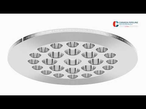
Watch: How Flow Conditioners Work — Installation and Performance
This video covers the installation process and operating principle of flow conditioners in industrial metering applications — practical reference material for your sales team and for customers who want to understand the technology before a purchase decision.
Your Path to Flow Conditioning Mastery
How This Guide Transforms Your Customer Relationships
The three fundamental shifts that happen when you master flow conditioning as a distributor:
From reactive support to proactive value. Instead of fielding calls about meters that “don’t read right,” you’re identifying the conditions that create those calls during the specification phase — before the meter ships. Your support burden drops. Your customers’ confidence in your product recommendations rises. The relationship shifts from transactional to advisory.
From product selling to system thinking. A distributor who recommends the right meter is doing their job. A distributor who recommends the right meter with the right conditioning, the right installation guidance, the right post-installation baseline documentation, and the right performance review 12 months later is building something competitors can’t easily replicate: a technical relationship with real institutional value.
From individual transactions to long-term accounts. The customers who understand that you actively protect the performance of their installations — and can prove it with documented before/after data — don’t comparison-shop at renewal. They expand the relationship. The conditioner conversation that starts with “you might want to add this to your meter order” ends with “you’re our preferred instrumentation partner for everything in this facility.”
The Next Step — Implementing This Framework Today
Three immediate steps:
Step 1 — Audit your current customer base. Identify 5–10 existing installations where you have knowledge of the upstream piping configuration. For any installation with elbows, valves, or reducers within 15D upstream of the meter without conditioning already in place, calculate the estimated measurement error cost using their annual fluid spend. This audit typically takes two to three hours and reliably identifies significant commercial opportunities.
Step 2 — Add the five specification questions to your inquiry template. Before the next new meter quote goes out, add the upstream piping configuration questions from Section 6 as required fields. Make conditioning the default conversation, not the exception.
Step 3 — Document one installation and build one case study. Choose your next conditioning installation and commit to measuring before and after. Collect 2–3 weeks of pre-installation meter data. Revisit 8 weeks post-installation for comparative data. Create a one-page summary showing the improvement. Use it in the next 10 sales conversations. The feedback loop from concrete, locally relevant data closes objections faster than any technical specification sheet.
🎯 Ready to start? Сайт Jade Ant Instruments Flow Conditioner Selection Guide provides the complete configuration decision tree, pressure drop calculation framework, and application-specific recommendations your team needs to make confident conditioning recommendations from your next customer inquiry. Contact the Jade Ant Instruments technical team for application-specific support — we help distributors build the expertise that builds lasting customer relationships.
Глоссарий основных терминов
| Term | Plain-Language Definition |
|---|---|
| Flow conditioner | A device installed upstream of a flow meter that restructures distorted fluid flow into a smooth, symmetric velocity profile that the meter was calibrated to measure |
| Velocity profile | The distribution of fluid speed across the pipe cross-section — in ideal (fully developed) flow, this forms a smooth bell curve; in disturbed flow, it is asymmetric or swirling |
| Swirl | A corkscrew-like rotation of the fluid, typically created by out-of-plane pipe elbows, that can persist for 40–80 pipe diameters without conditioning |
| Kp (pressure loss coefficient) | A dimensionless number describing how much pressure a conditioner removes from the flowing fluid — higher Kp means more conditioning effect but also more energy consumed |
| Pipe diameter (D) | The internal diameter of the pipe, used as the unit of measurement for straight-run distances (e.g., “10D upstream” means 10 times the pipe’s inside diameter) |
| AGA-3 | American Gas Association Report No. 3 — the industry standard governing orifice meter measurement of natural gas, specifying installation and conditioning requirements |
| ISO 5167 | International standard defining measurement of fluid flow by differential pressure devices, including specific installation and profile requirements |
| AGA-9 | American Gas Association Report No. 9 — the standard governing ultrasonic meter measurement of gas, specifying profile quality and installation requirements |
| Fully developed flow | A flow condition where the velocity profile is stable, symmetric, and reproducible — the condition assumed by most meter calibration procedures |
| Cavitation | The formation and violent collapse of vapor bubbles in a liquid, caused by localized low pressure from high-velocity flow; creates erosive damage on wetted surfaces |
| Custody transfer | A metering application where the measurement directly determines financial settlement between two parties — requiring the highest accuracy class and regulatory compliance |
| As-found deviation | The difference between a meter’s reading and the reference standard’s reading at the time of a calibration check, before any adjustment is made |
Часто задаваемые вопросы
FAQ 1: How do I know if my customer’s application actually needs a flow conditioner?
The practical decision starts with three questions: What is the upstream piping configuration? What measurement accuracy is required? And what are the financial or regulatory consequences of measurement error?
If there are elbows, valves, reducers, or tees within 20 pipe diameters upstream of the meter — and especially if multiple disturbances are present in different planes — conditioning should be assessed. Compare the actual available straight run against the requirements for the applicable standard (AGA-3, AGA-9, ISO 5167, or the meter manufacturer’s installation specification). If the installation falls short, the choice is between adding straight run pipe, relocating the meter, or installing conditioning. Of these three options, conditioning is almost always the most cost-effective in an existing facility. For new installations, conditioning during the design phase costs a fraction of piping relocation after the fact.
FAQ 2: What’s the real difference between various flow conditioner designs, and how do I choose?
The critical distinction is between designs that primarily remove swirl (tube bundles, straightening vanes) and designs that simultaneously remove swirl and redistribute the axial velocity profile (perforated plates). For applications with a single in-plane elbow as the only upstream disturbance, a tube bundle at adequate straight run distance may be sufficient. For applications with double out-of-plane elbows, reducers, or valves, only a perforated plate or hybrid combination achieves the profile quality required for compliance-grade metering. The selection decision comes down to: (1) identify the dominant disturbance type, (2) match to the conditioning mechanism that addresses it, and (3) confirm adequate downstream space for the specific design’s required settling distance.
FAQ 3: Can a flow conditioner fix an already-inaccurate meter installation?
For meters where the inaccuracy is caused by velocity profile distortion — the most common root cause — a properly specified conditioner will substantially improve accuracy, typically from ±3–8% to ±0.5–1.5% depending on the severity of the original disturbance. For meters where the inaccuracy has a different root cause — calibration drift, mechanical damage, wrong meter sizing — conditioning addresses a contributing factor but does not resolve the primary problem. Diagnosis before prescription: confirm that profile distortion is the dominant error source before specifying conditioning as the complete solution.
FAQ 4: How much does accuracy typically improve with proper flow conditioning?
The improvement range is wide because it depends on the starting condition. For a meter in a mild disturbance environment (single in-plane elbow, adequate straight run, currently at the edge of compliance), the improvement may be 0.5–1.0 percentage points — from ±1.5% to ±0.5–1.0%. For a meter in a severe disturbance environment (double out-of-plane elbows, valve downstream, no conditioning), the improvement can exceed 5–10 percentage points. FCI technical data supports accuracy and repeatability improvements of 50% or more in the most severe cases. The baseline determines the improvement ceiling — which is why measuring before and after every conditioning installation is such a valuable practice.
FAQ 5: What’s the typical cost of a flow conditioner compared to the meter itself?
Flow conditioners for standard industrial pipe sizes (1″–8″) typically run $800–$3,500 depending on design complexity, pipe size, and pressure rating. For comparison, the meter they support might cost $1,500–$15,000. The conditioner thus represents 5–25% of the meter’s cost, depending on the combination. The 10-year total cost comparison, however, reverses the apparent cost ratio: a $2,000 conditioner that reduces measurement error from 3% to 0.5% on a $500,000/year fluid spend creates $12,500/year in accuracy improvement value — a 5-year payback of $62,500 on a $2,000 investment. Present it as an investment, not an accessory.
FAQ 6: How does flow conditioning affect pressure drop and energy consumption?
Standard perforated plate conditioners have a pressure loss coefficient (Kp) of 2.0–5.0, creating a permanent pressure drop that depends on fluid velocity and density. For a typical 4″ natural gas line at 100 PSIG and 2 MSCFD, a Kp = 3.0 conditioner creates approximately 1.5–3 PSIG of pressure loss — a negligible fraction of system pressure. The energy cost of this loss, at typical compressor efficiencies, is typically $150–$600/year. Against $8,000–$45,000/year in measurement error cost, the energy penalty is immaterial. For low-pressure systems (below 30 PSIG), pressure drop becomes a more significant percentage of available pressure and should be calculated explicitly before specifying a high-Kp design.
FAQ 7: Are there applications where flow conditioning doesn’t help or could cause problems?
Conditioning provides no benefit — and should not be specified — for Coriolis meters (which are insensitive to profile disturbance) and positive displacement meters (which measure by volume trapping rather than velocity sensing). For turbine meters, over-aggressive conditioning (very high Kp plate too close to the rotor) can create excessive turbulence intensity that increases rotor bearing noise and wear. The installation spacing requirement — minimum 5D from conditioner exit to rotor face — prevents this. In highly space-constrained installations, if the only feasible conditioner position creates a 2–3D conditioner-to-meter gap, a lower-Kp design is preferable to a high-Kp plate at insufficient spacing.
FAQ 8: How do I explain flow conditioning benefits to customers who are purely cost-focused?
Lead entirely with money. Skip the technical explanation of velocity profiles and Kp values entirely. The conversation: “Your meter’s current installation has [describe the upstream conditions]. Based on field data for this configuration, meters in similar setups typically run 2–4% inaccurate. At your annual [gas/liquid] spend of $X, that’s $Y per year in measurement-related cost. The conditioner costs $Z. Payback in [months]. After that, the savings continue every year. Want me to show you the calculation?” Cost-focused customers respond to that conversation — because they are being shown exactly what the cost is and exactly what the payback is. Abstraction doesn’t work with cost-focused buyers. Specificity does.
FAQ 9: What happens if a customer refuses to install a flow conditioner and experiences problems later?
Document your recommendation in writing at the time it is made — either in the quotation notes, a follow-up email, or both. State clearly: “Based on the upstream piping configuration you described (double out-of-plane elbows at approximately 6D upstream), we recommend including a flow conditioner with this installation. Without conditioning, measurement accuracy may be reduced to ±3–5% in this configuration. We are happy to proceed without conditioning per your preference — please confirm in writing.” This documentation protects you from a future claim that you sold a meter that “didn’t work” — and it creates a professional record of the technical advisory relationship that keeps you credible even when customers make sub-optimal decisions.
FAQ 10: Can flow conditioners be retrofitted into existing installations?
Yes — most conditioners are designed as spool pieces that replace a section of existing pipe, requiring only a pipe cut and two flanged connections. For installations where the pipe cannot be cut during operation, a hot-tap style insertable conditioner provides a shutdown-free retrofit option. The cost reality: a straightforward spool piece retrofit in a 4″ line typically costs $300–$800 in labor plus the conditioner hardware. Where the existing piping requires rerouting to create adequate space, total installation cost can rise to $3,000–$8,000. The retrofit value proposition is still usually positive when the measurement error cost is quantified — but the total installation cost must be part of the ROI analysis, not just the conditioner price.
FAQ 11: How often do flow conditioners need maintenance or replacement?
Quality solid plate and tube bundle conditioners require no routine maintenance and have essentially unlimited mechanical life in clean service. They are passive devices with no moving parts, no wear surfaces, and no calibration requirement. The maintenance task in clean applications is a visual inspection every 12 months: check for particulate accumulation on the upstream face of the plate, verify no mechanical damage, confirm the mounting flange shows no signs of leakage. In dirty applications — pipeline startup commissioning, aging gas systems with scale, or liquid applications with particulate — inspect quarterly and clean as needed. Replacement is only required if the piping is modified or if the conditioner sustains physical damage during a major pressure event.
FAQ 12: What’s the relationship between flow conditioning and calibration intervals?
Properly conditioned meters show more stable long-term calibration behavior than unconditioned meters operating in the same disturbance environment. The reason is that profile-distortion-induced forces accelerate internal wear (especially in turbine and vortex meters) and contribute to the measurement uncertainty that triggers recalibration. Remove the distortion, extend the calibration cycle. In practice, distributors who track before-and-after calibration performance for conditioned installations consistently report interval extensions from annual to biennial in moderate-disturbance applications. Document this by comparing the “as-found deviation” at each calibration visit over a 4–6 year window — the trend tells the story more powerfully than any single data point.
FAQ 13: Are there industry standards or regulations that mandate flow conditioning?
Flow conditioning is explicitly required by several major standards, rather than just recommended. AGA-3 / ISO 5167 for orifice metering specifies installation conditions that can only be met in typical industrial piping configurations with the addition of a compliant conditioner. AGA-9 for ultrasonic metering specifies profile quality requirements at the meter inlet that similarly require conditioning in most non-ideal installations. API Chapter 14 for natural gas custody transfer references specific installation requirements that incorporate conditioning for reduced-run designs. Beyond standards compliance, many energy sector operators and utilities specify flow conditioning in their internal procurement and installation standards for all custody transfer and billing-grade measurement points. For regulated industries — natural gas distribution, petroleum pipeline operations, water utilities — checking the applicable standard before specifying any installation without conditioning is the professionally responsible approach.
FAQ 14: How do I train my sales team to sell flow conditioning when customers don’t understand why they need it?
The training framework is built around problems, not products. Train your team to ask the upstream piping questions first, before talking about conditioners at all. When a customer answers that they have two elbows in different planes at 4D upstream of their turbine meter, your rep should be able to say: “That configuration typically produces 4–8% measurement error in turbine applications. At your throughput, that’s approximately $X per year in measurement-related cost. Can I show you how we address that?” The customer recognizes the problem — and from there, the conditioner is the solution they want, not something you’re pushing. Role-play these specification conversations with your team using real customer scenarios from your order history. Five practice conversations are more effective than five hours of classroom instruction.
FAQ 15: What’s the best way to document performance improvement after installing a flow conditioner?
The process has three stages. Before installation: collect a minimum of 2–3 weeks of daily meter data (recorded totalized flow or average flow rate), document the most recent calibration as-found deviation, and photograph the upstream piping showing the disturbance conditions. After installation: wait 4–6 weeks for operating conditions to stabilize with the new conditioning, then collect another 2–3 weeks of data under comparable conditions. Calculate: the standard deviation of daily readings (lower standard deviation indicates improved repeatability), the comparison of any reference meter readings if available, and — at the next calibration event — the as-found deviation. Compile these three data points into a one-page Before / After report. Present it to the customer’s management team. File it as a case study. Use it in future sales conversations. This documentation turns a technical success into a commercial asset that continues to generate value long after the installation is complete.
For application-specific flow conditioner selection support, complete configuration decision trees, and distributor partnership resources, visit jadeantinstruments.com. Start with the Flow Conditioner Selection Guide for interactive configuration guidance, or explore the Flow Meter Installation Best Practices Guide for the complete straight-run and commissioning reference your team needs.