Natural gas distributors face mounting pressure to meet regulatory standards while controlling operational costs. Selecting the right custody transfer flow meter isn’t just about compliance—it’s about protecting your bottom line, avoiding costly penalties, and building customer trust. This comprehensive guide shows you how to choose meters that meet every regulatory requirement while maximizing your ROI.
Why Custody Transfer Meters Matter More Than You Think
Here is a number that most of your clients have never sat down to calculate: a single mid-sized natural gas distribution station processing a 0.25% measurement error can generate nearly $500,000 USD in annual financial impact at $3/MSCF (Thousand Standard Cubic Feet). That figure comes from published Emerson field analysis, and it applies to a modest-volume station by today’s standards.
Now scale that across a distributor’s entire network of custody transfer points.
The stakes at custody transfer are categorically different from any other measurement application. When gas changes hands—from pipeline company to local distribution company, from distributor to industrial customer, from importer to utility—the meter reading is the transaction. It is the billing record, the regulatory submission, and the legal defense if a dispute arises. “Close enough” is not an accuracy specification. It is a liability position.
For distributors and agents who supply flow instrumentation to natural gas companies, this creates a specific commercial reality: your clients are not buying meters. They are buying measurement integrity, regulatory standing, and financial certainty. The guide that follows is designed to give you the technical grounding, the regulatory framework, and the ROI language to serve them well in that context.
Отраслевой обзор: According to the American Gas Association, measurement-related billing disputes in North American natural gas distribution cost the industry an estimated $1.2 billion annually in administrative, legal, and reconciliation costs—costs that properly specified custody transfer meters would largely eliminate.
 A custody transfer metering station at a natural gas distribution point — the meter reading at these installations is the financial transaction. Measurement error here is not an operational issue; it is a financial and legal one.
Understanding Custody Transfer Flow Meters and Why They’re Non-Negotiable for Your Business
What Custody Transfer Flow Meters Actually Do (and Why “Close Enough” Isn’t Good Enough)
A custody transfer meter (also called a fiscal meter) is any flow measurement device used at a point where ownership or financial responsibility for natural gas changes hands. The defining characteristic is not the hardware—it is the regulatory and contractual framework that surrounds it.
At a custody transfer point, the meter reading is simultaneously: a billing document, a regulatory compliance record, an audit trail, and a legal instrument in the event of a dispute. Every cubic meter that the meter over- or under-reads is a cubic meter that will eventually surface in a billing dispute, a regulatory audit finding, or a contractual reconciliation claim.
The technical requirement that flows from this context is strict measurement accuracy—not as an engineering preference, but as a legal obligation. AGA Report No. 9 for ultrasonic meters requires ±0.7% accuracy across the meter’s entire flow range. AGA-3/API 14.3 for orifice applications requires measurement uncertainty that satisfies the installation and calibration conditions of the standard. These are not soft targets; they are the minimum conditions for a measurement to be legally defensible as a custody transfer record.
The Critical Difference Between Custody Transfer and Non-Custody Applications
A non-custody meter—used for process optimization, leak detection, or operational balancing—can tolerate ±2–5% accuracy without material consequence. If the process optimization algorithm runs on data that is 3% high, the plant operates slightly less efficiently. The financial impact is real but diffuse and indirect.
A custody transfer meter operating at ±3% on a distribution main delivering 5 million MSCF per year at $4/MSCF is generating $600,000 per year in erroneous billing—either undercharging customers or overcharging them. The direction of the error determines whether your client faces revenue loss or a costly refund obligation when the error is discovered.
The regulatory distinction is equally sharp. Non-custody meters have no mandatory accuracy standard, no required calibration interval, and no approval process for installation. Custody transfer meters must be type-approved or individually certified, installed according to the applicable standard, calibrated at specified intervals by accredited facilities, and documented to a standard that satisfies regulatory audits.
How Measurement Accuracy Directly Impacts Financial Settlements and Customer Relationships
The financial exposure from custody transfer measurement inaccuracy concentrates in three areas: billing error (direct revenue gain or loss on every measurement), dispute resolution (administrative and legal costs when billing discrepancies surface), and regulatory reconciliation (mandatory retroactive correction of measurement errors identified during audits).
At a medium-volume distribution station processing 2,000 MSCFD (million standard cubic feet per day) at $4/MSCF, the annual billing exposure from a 1% measurement error is:
For a distributor managing 20 such stations across a regional network, the total annual exposure from a 1% fleet-wide accuracy gap is approximately $584,000/year—from an error rate that is well within the tolerance of an aging, under-maintained meter fleet.
The Real Cost of Choosing the Wrong Meter
Financial Penalties from Regulatory Non-Compliance
The penalty structure for custody transfer measurement non-compliance in U.S. natural gas distribution is defined across multiple regulatory bodies, and the numbers are not trivial.
FERC (Federal Energy Regulatory Commission) violations for fiscal measurement non-compliance carry penalties up to $1 million per violation per day under the Energy Policy Act of 2005 for willful or knowing violations. For standard compliance failures, the practical range is $10,000–$100,000 per violation, with additional requirements for retroactive measurement correction covering the entire out-of-compliance period.
State utility commissions impose their own penalty structures. A Texas distribution company found to have operated uncertified meters at three custody transfer points for 14 months faced a $375,000 settlement with the Railroad Commission, plus mandatory retroactive billing reconciliation across all affected accounts.
Beyond direct penalties, regulatory findings trigger mandatory audit programs, increased inspection frequency, and reputational consequences in regulatory relationships that affect future rate case approvals—costs that are harder to quantify but often exceed the direct penalty amount.
Revenue Loss from Measurement Inaccuracy and Billing Disputes
The revenue exposure from measurement inaccuracy is not speculative—it is computable from the meter’s accuracy specification, the operating flow rate, and the commodity value. What most distributors underestimate is the cumulative effect of multiple meters, each drifting slightly, across a multi-year operating period without recalibration.
A turbine meter that was calibrated at ±0.5% at installation will, under typical operating conditions, drift by 0.15–0.3% per year of operation. After five years without a proving cycle, that meter may be operating at ±1.5–2.0% systematic error—entirely undetected by normal operations monitoring. Across a portfolio of 30 custody transfer stations, the cumulative annual revenue exposure from this level of drift can reach seven figures.
The customer relationship dimension is equally significant. When a downstream customer discovers—through their own meter verification or an independent audit—that your network has been over-billing them for 18 months, the commercial damage extends far beyond the billing reconciliation. Contract renewal negotiations, rate case proceedings, and service territory competition all become materially harder when your measurement integrity has been publicly questioned.
Navigating Regulatory Requirements: Standards You Must Meet
Key Regulatory Frameworks Every Natural Gas Distributor Must Understand
API (American Petroleum Institute) Standards and What They Require of You
Сайт American Petroleum Institute publishes the primary measurement standards for natural gas custody transfer in the United States. The most directly relevant are:
API Manual of Petroleum Measurement Standards (MPMS) Chapter 14, Section 3 (AGA-3) governs orifice measurement of natural gas. It specifies meter tube dimensions, orifice plate tolerances, differential pressure measurement requirements, and installation conditions including upstream and downstream straight-pipe run requirements. An installation that does not meet AGA-3 Chapter 14.3 dimensional requirements does not produce a compliance-grade measurement regardless of the quality of the meters themselves.
API MPMS Chapter 21 covers flow measurement using electronic methods, including electronic flow computers and data loggers. Any custody transfer installation using electronic calculation of flow from primary element data must comply with Chapter 21 documentation and audit trail requirements.
For gas distributors, API standards represent the minimum floor—state regulatory commissions often impose additional requirements on top of them.
AGA (American Gas Association) Measurement Guidelines and Their Enforcement
The American Gas Association publishes the measurement standards that function as the operational reference for natural gas custody transfer in North America. The three most relevant to distributors are AGA-3 (orifice measurement, shared with API 14.3), AGA-7 (turbine meters), and AGA-9 (multipath ultrasonic meters).
AGA-7 defines the installation, performance testing, calibration, and documentation requirements for turbine meters in custody transfer service. The key accuracy requirement is ±1% of reading across the flow range from Qmin to Qmax, with ±0.5% of reading for meters with individual flow calibrations traceable to national standards.
AGA-9 governs multipath ultrasonic meters—the technology increasingly preferred for new custody transfer installations. AGA-9 requires ±0.7% at flow rates between Qtransition and Qmax, and ±1.4% between Qmin and Qtransition. These requirements assume factory calibration with a valid calibration certificate and an installation that meets the standard’s upstream piping and flow conditioning requirements.
Enforcement of AGA standards occurs through state utility commission audits, PHMSA (Pipeline and Hazardous Materials Safety Administration) inspection programs, and contractual measurement audits triggered by billing disputes. Inspectors who cite AGA non-compliance can require immediate meter replacement, retroactive measurement correction, and remediation plan submission—without a grace period.
NIST Traceability and Certification: Building Your Compliance Foundation
Why NIST-Traceable Calibration Protects You Legally and Financially
NIST traceability means that your meter’s calibration can be linked, through a documented and unbroken chain of comparisons, to measurement standards maintained by the National Institute of Standards and Technology. Each calibration in the chain carries documented uncertainty at each step.
The legal and financial importance of this traceability is straightforward: without it, you have no defensible proof of measurement accuracy. In a billing dispute, your measurement record is only credible if you can demonstrate that the meter producing those records was calibrated against a standard that is independently verifiable. A calibration certificate from a lab with no NIST traceability is not evidence—it is a document.
For natural gas distributors operating under state utility commission oversight, NIST-traceable calibration is typically a regulatory requirement, not a best practice recommendation. Meters found to lack traceable calibration during audits are treated as uncalibrated meters—requiring immediate replacement and retroactive correction of all measurements made since the last valid calibration.
How to Verify Your Meter Supplier’s Certification Credentials
Supplier certification verification is a due diligence step that many distributors skip—and that regulatory auditors specifically look for in supply chain documentation. The verification process should include:
Requesting the supplier’s ISO/IEC 17025 accreditation certificate for their calibration laboratory—this is the international standard for calibration and testing laboratory competence. ISO/IEC 17025 accreditation is scope-specific; verify that the scope covers the flow rates, pressures, and gas compositions relevant to your application. Checking the supplier against NIST’s NVLAP (National Voluntary Laboratory Accreditation Program) database for flow measurement calibration. Requesting calibration certificates for representative meters with the full measurement uncertainty chain documented. Suppliers who cannot provide these documents are not suitable for custody transfer applications, regardless of other commercial considerations.
Regional and State-Specific Compliance Requirements
How Regulations Vary Across Your Distribution Territories
Natural gas distribution in the United States is regulated at both federal and state levels, and state requirements vary significantly. California’s CPUC (California Public Utilities Commission) has specific meter accuracy verification frequency requirements that exceed federal minimums. Texas Railroad Commission rules specify installation requirements for meters serving customers above certain volume thresholds. Some states require measurement system designs to be pre-approved by the commission before installation, while others operate post-installation audit programs.
For distributors operating across multiple states, maintaining a jurisdiction-by-jurisdiction compliance matrix is not optional—it is the only way to ensure that no territory is operating under an undocumented assumption about what the local rules require.
Managing Compliance Across Multiple Jurisdictions Without Operational Chaos
The practical approach to multi-jurisdiction compliance is to build your standard practices around the most stringent requirements in your operating territory, then document jurisdiction-specific variations. A meter that meets California CPUC requirements will meet Texas Railroad Commission requirements. A proving frequency that satisfies New York PSC rules will satisfy Colorado PUC rules. Building to the highest bar eliminates the risk of a compliance gap when operational decisions are made quickly and the jurisdictional nuances aren’t top of mind.
Centralizing compliance documentation in a database that tracks each custody transfer point’s jurisdiction, applicable standard, last calibration date, next required proving date, and equipment certification status eliminates the manual tracking that leads to missed proving windows and audit findings.
 Pressure regulation and measurement at a natural gas distribution point — every element of this installation, from the meter to the pressure transducer to the electronic flow computer, must meet regulatory specifications.
Custody Transfer Meter Types: Selecting the Right Technology for Your Network
Turbine Meters—Reliability at Scale
When Turbine Meters Deliver the Best Accuracy and ROI for Your Operation
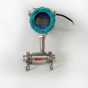
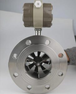
Turbine meters operate by placing a multi-bladed rotor in the gas stream—the rotation rate of the rotor is proportional to gas velocity, and the pulse output provides a volumetric flow count. For clean, dry natural gas at moderate to high flow rates with stable operating conditions, the turbine meter is a proven, well-understood technology with decades of AGA-7 compliance data behind it.
The applications where turbine meters consistently deliver their best performance are: high-volume transmission stations with stable flow and gas composition, locations where a long track record of regulatory acceptance is commercially important, and installations where the piping and maintenance infrastructure is already configured for turbine meter service.
A properly calibrated turbine meter in custody transfer gas service achieves ±0.5% of reading over its linear flow range—competitive with all technologies except multi-path ultrasonic—and its pulse-based output integrates cleanly with electronic flow computers for AGA-7 compliant volume calculation.
Maintenance Requirements and Total Cost of Ownership Considerations
The fundamental limitation of turbine meters is their moving parts. Rotor bearings wear under continuous gas flow, and bearing wear causes the rotor to slow relative to actual gas velocity—producing systematic under-reading that accumulates silently between proving cycles. In clean, dry natural gas service, bearing life is typically 18–36 months before a proving run will reveal drift exceeding the AGA-7 tolerance.
For distributors, this maintenance reality means: turbine meter custody transfer stations need a proving program with sufficient frequency to catch drift before it creates a regulatory finding. AGA-7 recommends proving at intervals defined by the regulatory authority, but as a practical baseline, annual proving at high-volume stations and biennial proving at lower-volume points is the minimum defensible program. Each proving cycle carries direct costs (prover operation or calibration laboratory fees) plus indirect costs (operational coordination, documentation, potential measurement interruption).
Ultrasonic Meters—Modern Accuracy with Fewer Moving Parts
How Ultrasonic Technology Reduces Maintenance Costs and Downtime
Multipath ultrasonic meters—specifically the transit-time designs governed by AGA-9—measure gas velocity by comparing the travel time of ultrasonic pulses sent upstream versus downstream through the flowing gas. The time difference is proportional to gas velocity; multiple acoustic paths through different chords of the pipe cross-section are combined to calculate the average velocity profile and thus the volumetric flow rate.
The defining maintenance advantage is the complete absence of moving parts. No rotors, no bearings, no mechanical wear mechanisms. The transducers are mounted in the pipe wall with no intrusion into the gas stream (in some configurations). A multipath ultrasonic meter that was installed and calibrated correctly will, in clean natural gas service, maintain its calibration accuracy for 3–5 years without requiring a proving run—versus the 12–24 month interval typically required for turbine meters.
Для natural gas custody transfer applications, the multipath ultrasonic meter’s combination of ±0.7% accuracy (AGA-9 compliant), reduced proving frequency, and self-diagnostic capability has made it the dominant technology choice for new custody transfer installations globally. A major North Sea operator that switched from turbine to 4-path ultrasonic meters across 40 fiscal gas measurement stations reported a reduction in annual calibration costs of approximately $1.8 million—from reduced proving frequency alone.
Gas Composition Challenges and How to Address Them in Your Network
Transit-time ultrasonic meters depend on the speed of sound in the gas, which varies with gas composition, temperature, and pressure. For natural gas with variable BTU content or significant compositional variation across seasons or supply sources, the meter’s flow computer requires accurate gas composition data to calculate the true volumetric flow rate.
The solution for composition-variable applications is either a dedicated gas chromatograph (GC) providing real-time composition data to the flow computer, or a flow computer configured for the worst-case composition variation with documented uncertainty analysis demonstrating that the resulting measurement uncertainty remains within AGA-9 limits. For distribution networks served by multiple gas sources with significantly different heating values, the GC approach is the only technically defensible path to a compliant measurement.
Orifice Plate Meters—Proven Performance in Demanding Conditions
Advantages for High-Volume Custody Transfer Applications
The orifice plate meter—an диафрагма (a flat plate with a precisely machined central bore) installed in a meter tube with differential pressure taps before and after the plate—is the most standardized measurement technology in the natural gas industry. AGA-3/API 14.3 defines orifice measurement with a precision and completeness unmatched by any other measurement standard, and the orifice meter’s performance characteristics are the most thoroughly documented in the technical literature.
For high-volume custody transfer applications where measurement uncertainty must be demonstrably below 0.5%, a properly designed and maintained AGA-3 compliant orifice meter installation with a high-performance differential pressure transmitter and a calibrated pressure and temperature compensation system can achieve measurement uncertainty in the 0.3–0.5% range—competitive with turbine and ultrasonic systems.
The orifice meter’s advantage in certain applications is its robustness to gas composition variation: the differential pressure measurement depends on gas density (which is calculated from composition, pressure, and temperature rather than inferred from acoustic properties), making it inherently more tolerant of BTU variability than ultrasonic systems.
Pressure Drop Implications and Energy Efficiency Trade-Offs
The orifice plate creates a permanent pressure drop in the gas stream—the fundamental physical cost of the differential pressure measurement principle. This pressure drop is proportional to the square of flow velocity and varies with the orifice beta ratio (the ratio of orifice bore to pipe bore). At typical distribution system operating conditions, orifice plate pressure drops of 5–15 PSIG are common.
For clients operating near system pressure limits, or for installations where compression costs are a significant operating expense, this pressure drop has a real financial cost:
At 10 PSIG pressure drop on a 1,000 MSCFD station, the annual compression energy penalty is on the order of $15,000–$35,000 depending on local electricity cost. Over a 10-year meter life, this energy cost can exceed the total capital cost of switching to a lower-pressure-drop technology—a trade-off worth modeling explicitly in high-volume applications.
Rotary Displacement Meters—When Precision Matters Most
Ideal Applications Within Your Distribution Network
Rotary displacement meters (also called rotary gas meters or positive displacement meters) measure gas by trapping specific volumes between rotating figure-eight-shaped rotors and counting the number of rotation cycles. Unlike inferential meters (turbine, orifice, ultrasonic) that calculate flow from measured velocity, rotary meters count discrete volumes directly—a measurement approach that is inherently less sensitive to flow profile disturbances and gas composition variations.
For lower-flow custody transfer applications—commercial and small industrial customers with flow rates typically below 5,000 SCFH (standard cubic feet per hour)—rotary displacement meters offer high accuracy (±1% of reading across their full flow range) with a measurement principle that is straightforward to verify and maintain. They are the dominant technology for commercial gas customer metering in North American gas distribution, and their regulatory acceptance is universal.
Sensitivity Factors That Affect Accuracy in Real-World Conditions
Rotary meters are sensitive to gas pressure and temperature variations because their displacement volume per rotation is defined at a specific reference condition. Most modern rotary meters include integral temperature compensation, but pressure compensation requires a separate device unless a pressure-correcting meter (an index-corrected model) is specified.
Lubrication is the primary maintenance requirement: rotary meter timing gears require periodic oil changes to prevent bearing wear that would shift the displacement volume per rotation. AGA-7 guidelines for rotary meters specify that proving should be performed after any lubrication service to verify that the K-factor has not shifted. For distributors managing large populations of rotary meters in distribution service, a systematic lubrication and proving program is the foundation of custody transfer compliance.
Measurement Accuracy Standards: What “Approved” Really Means
Understanding Meter Accuracy Classes and Tolerance Levels
When a meter is described as “custody transfer grade” or “Class 1 accuracy,” the specific performance requirement behind that label depends on the applicable standard. The most important accuracy requirements for natural gas custody transfer in North America are:
| Стандартный | Тип счетчика | Accuracy Requirement | Диапазон расхода |
|---|---|---|---|
| AGA-3 / API 14.3 | Диафрагма | Compliance with installation + calibration conditions | Full range |
| AGA-7 | Turbine Meter | ±1.0% of reading (±0.5% with individual calibration) | Qmin to Qmax |
| AGA-9 | Ultrasonic (Multi-path) | ±0.7% of reading | Qt to Qmax |
| AGA-9 | Ultrasonic (Multi-path) | ±1.4% of reading | Qmin to Qt |
| ISO 17089 | Ultrasonic (All types) | ±1.0% of reading | Full range |
| OIML R 137 | Gas Meters (General) | Class 1: ±1.0%; Class 0.5: ±0.5% | Q1 to Qmax |
Table 1: Custody Transfer Accuracy Requirements by Standard and Meter Type
The critical insight for distributors is that “accuracy class” is not a single number—it is a performance specification that applies over a defined flow range, under defined conditions, following a defined calibration process. A turbine meter that achieves ±0.5% at its calibration flow rate may produce ±2% errors at flow rates below its AGA-7 minimum (Qmin), which occurs when a customer’s actual usage pattern doesn’t match the meter’s rated flow range.
How Accuracy Class Selection Impacts Your Billing Accuracy and Customer Disputes
Selecting a meter with the appropriate accuracy class for the actual flow range at the custody transfer point is one of the most consequential technical decisions in the specification process—and one of the most commonly neglected.
A turbine meter sized for a maximum flow of 10,000 MSCFH installed at a station that regularly operates at 1,000 MSCFH (10% of rated maximum) is operating below its AGA-7 Qmin. The accuracy specification does not apply in this range, and the actual measurement error may be ±5–10%. The meter is “approved” and “certified”—but the measurement it produces at the operating condition is not within the accuracy class that the approval covers.
For distributors advising clients on meter sizing, this means: specify the meter for the expected operating flow range, not the maximum possible flow. Oversizing meters to “be safe” on capacity creates under-range operation that is far more damaging to measurement accuracy than running at the upper end of the rated range.
Installation Requirements That Directly Affect Measurement Integrity
Proper Upstream and Downstream Piping Configurations
Every custody transfer measurement standard specifies minimum upstream and downstream straight-pipe run requirements—lengths of unobstructed straight pipe before and after the meter that allow the gas velocity profile to stabilize before reaching the measurement element. These requirements exist because most meter calibrations assume a specific, well-defined inlet velocity profile. Elbows, valves, reducers, and headers upstream of the meter distort that profile, introducing systematic measurement errors that can persist even in a perfectly calibrated meter.
| Тип счетчика | Min. Upstream Straight Run | Min. Downstream Straight Run | Standard Reference |
|---|---|---|---|
| Orifice Plate (D/2 taps) | 20D–44D (varies by disturbance) | 5D | AGA-3 / API 14.3 Table A-5 |
| Turbine Meter | 10D | 5D | AGA-7 Section 7 |
| Ultrasonic (4-path) | 10D | 5D | AGA-9 Section 8 |
| Rotary Displacement | 5D | 3D | Manufacturer + state authority |
Table 2: Minimum Straight-Pipe Run Requirements by Meter Type (D = pipe nominal diameter)
These are minimum requirements under favorable conditions. Severe upstream disturbances—multiple out-of-plane elbows, partially open control valves, abrupt reducers—may require flow conditioning in addition to straight-pipe runs to achieve compliance-grade inlet conditions.
Temperature and Pressure Compensation—Why They’re Not Optional
Custody transfer in natural gas is always measured in reference conditions—typically 60°F and 14.73 PSIA (pounds per square inch absolute) for North American custody transfer. The gas flowing through the meter is at actual operating conditions, which can range from -20°F to 120°F and 50 PSIG to 1,000 PSIG depending on the system location.
Converting from actual to reference conditions requires real-time temperature and pressure measurement, plus a calculation using the gas compressibility factor (Z-factor). The electronic flow computer (EFC) or flow computer integral to the meter performs this calculation continuously. An installation without functioning temperature and pressure compensation is not producing a reference-condition volume count—it is producing an actual-condition count that may differ from the custody transfer volume by 5–15% depending on operating conditions.
Verification, Proving, and Recalibration Schedules
How Often You Actually Need to Verify Your Meters (and What It Costs)
Proving—the process of comparing a custody transfer meter’s output against a reference standard of known accuracy—is the primary mechanism for detecting meter drift. The proving interval requirement varies by jurisdiction and meter type, but a practical schedule based on industry best practices is:
- High-volume custody transfer points (>10,000 MSCFD): Annual proving, with diagnostic monitoring of turbine or ultrasonic meter health between formal provings
- Medium-volume points (1,000–10,000 MSCFD): Biennial proving, with annual confirming checks
- Lower-volume points (<1,000 MSCFD): Per state regulatory requirements (typically every 3–5 years for rotary meters)
The direct cost of a formal proving event for a 6-inch custody transfer station (mobilization of a prover, reference equipment, data collection, and certificate issuance) typically ranges from $3,500 to $12,000 depending on meter size, access conditions, and the calibration company’s mobilization cost. Annual proving for a 20-station network is a $70,000–$240,000 annual operating line item—significant enough that the choice of meter technology (and its inherent drift rate) materially affects operating costs over a 10-year horizon.
Building a Sustainable Proving Program That Fits Your Operational Budget
A sustainable proving program balances regulatory compliance with operational cost through risk-based interval setting. High-volume, high-commodity-value stations justify annual proving because the financial exposure per unit of meter drift is highest there. Lower-volume stations can safely extend to biennial or triennial intervals if the meter type has low inherent drift (ultrasonic, for example, typically drifts more slowly than turbine) and in-service diagnostic monitoring confirms no anomalies between formal provings.
Documenting the risk basis for interval decisions—and reviewing that basis annually as operational conditions change—is both good practice and excellent regulatory defense. An audit finding that you exceeded a proving interval is far less serious when accompanied by documented risk analysis justifying the extension than when it reflects administrative oversight.
Certification Requirements: Your Roadmap to Regulatory Approval
Type Approval vs. Individual Meter Certification—What Your Business Needs
Type approval means that a specific meter model has been independently tested against the applicable performance standard (AGA-7, AGA-9, etc.) and approved for use in custody transfer applications. Any individual meter manufactured to the approved type—with documented quality control verifying conformance to the approved design—can be installed in custody transfer service without individual testing of that specific unit.
Individual meter certification means that a specific meter unit, identified by serial number, has been tested and its calibration certificate covers only that exact unit. If a different unit of the same model is installed, it requires its own individual calibration.
For gas distributors managing large meter populations, type approval is the operationally practical path. It allows standardized procurement, inventory management, and installation procedures—a certified turbine meter model from an approved manufacturer can be ordered, received, and installed without a separate approval process for each unit. The type approval documentation—the approval certificate, the performance test report, the applicable standards reference—travels with the meter model, not with each individual unit.
Individual certification is required for high-value custody transfer points where the financial stakes justify the additional cost and delay, and where jurisdictional requirements specify individual calibration rather than accepting type approval.
The Certification Process from Application to Installation
Documentation and Technical Specifications Required for Approval
The regulatory approval process for a custody transfer meter installation typically requires: the meter manufacturer’s type approval certificate (from NTEP, a state weights and measures laboratory, or the relevant international certification body), factory calibration certificate with NIST-traceable calibration chain, meter installation design drawing showing compliance with applicable straight-pipe run requirements, electronic flow computer type approval and software version documentation, gas composition and operating condition parameters for the specific installation point, and a commissioning plan including initial proving procedure.
State utility commissions that require pre-installation approval (as opposed to post-installation audit) typically have 30–90 day review processes for new custody transfer installations. Submitting a complete, well-documented application at the first submission avoids the delays from requests for additional information that can push timelines out by months.
Working with Regulatory Bodies to Expedite Approval Without Cutting Corners
The most effective approach to regulatory relationships in custody transfer measurement is proactive engagement, not reactive compliance. Regulators who know your company as a competent, transparent operator respond to approval applications very differently than those who have only seen you during enforcement proceedings.
Developing a relationship with the measurement specialist at your state regulatory commission before you need an expedited approval—attending industry standards meetings they participate in, inviting them to inspection events at your measurement stations, submitting application packages that exceed minimum documentation requirements—creates a foundation for constructive interactions when time pressure is high.
Maintaining Certification Status and Avoiding Compliance Lapses
Documentation Requirements That Protect You During Audits
The documentation requirements for custody transfer meter compliance are extensive and non-negotiable. An audit that cannot find the required documentation will treat the undocumented period as non-compliant—even if the meter was, in fact, operating correctly throughout. The required documentation package for each custody transfer point includes:
Type approval certificate (current, with valid scope for the operating conditions), individual calibration certificate (most recent, within the required interval), installation records (dimensions, piping configuration, date of installation), proving records (all formal proving events, results, and follow-up actions), electronic flow computer configuration records (settings, software versions, coefficient values), and maintenance records (all service events, parts replacements, and their impact on calibration status).
This documentation must be retained for the period specified by the applicable regulatory authority—typically 5–10 years. The practical approach is a metering management system (software or structured spreadsheet) that links each station to its complete document package and generates alerts for upcoming proving dates and certification renewals.
How to Prevent De-Certification and the Business Impact of Losing Approval
Loss of certification at a custody transfer point—through expired type approval, lapsed proving certificate, or unauthorized equipment modification—requires the station to cease custody transfer billing immediately until the certification is restored. During the recertification period, gas delivery continues but billing is suspended or flagged as provisional, creating significant customer relationship stress and potential revenue recovery difficulties for the uncertified measurement period.
Prevention is categorically less expensive than recovery. A metering management program that tracks certification expiry dates, proving due dates, and documentation completeness—with automatic alerts 60 and 30 days before any deadline—eliminates compliance lapses that occur from administrative oversight rather than equipment failure.

Selecting Your Meter: A Decision Framework That Protects Your Business
Assessing Your Network’s Actual Measurement Needs
Flow Rate Ranges, Pressure Conditions, and Gas Composition in Your Territory
The selection process begins not with meter technology but with a precise characterization of each custody transfer point’s operating envelope. The four parameters that drive the technology selection are: flow rate range (minimum, normal, and maximum operating flow, expressed as MSCFD or MSCFH), operating pressure range (minimum and maximum, expressed as PSIG), gas temperature range, and gas composition (BTU content, specific gravity, and any contaminants including water vapor, H₂S, or heavier hydrocarbons).
This characterization must use actual operating data—not design capacity or maximum contract quantities. A meter specified for maximum design flow at a station that routinely operates at 20% of capacity is chronically outside its linear operating range. A meter specified for summer operating conditions at a station that sees winter peak flows 4× the summer baseline will underperform in the season that matters most for billing accuracy.
Identifying High-Value Custody Transfer Points Where Accuracy Matters Most
Not all custody transfer points carry equal financial stakes. A strategic accuracy investment program prioritizes the highest-value points—those with the highest volumetric throughput, the highest commodity value per unit, or both—for the most precise and proven measurement technology. Secondary stations serving smaller customers or carrying lower throughput can be served with lower-cost, well-maintained standard meter technology without compromising the financial performance of the network as a whole.
Total Cost of Ownership Analysis—Looking Beyond the Purchase Price
The most common mistake in custody transfer meter procurement is evaluating options on purchase price alone. A 10-year total cost of ownership (TCO) model that includes all cost elements presents a materially different ranking of options than a simple capital cost comparison.
| Статья расходов | Turbine Meter | Ultrasonic (Multi-path) | Диафрагма |
|---|---|---|---|
| Purchase price (6″) | $8,000–$18,000 | $25,000–$60,000 | $5,000–$15,000 |
| Installation (full meter run) | $15,000–$30,000 | $15,000–$30,000 | $15,000–$40,000 |
| Annual proving cost | $5,000–$12,000/yr | $2,500–$6,000/yr | $3,000–$8,000/yr |
| Bearing replacement (turbine) | $1,200–$3,000/event | Н/Д | Н/Д |
| 10-year maintenance total | $25,000–$55,000 | $8,000–$20,000 | $12,000–$30,000 |
| 10-year TCO estimate | $63,000–$115,000 | $65,000–$116,000 | $45,000–$93,000 |
| Proving interval | Ежегодный | Biennial | Ежегодный |
Table 3: 10-Year Total Cost of Ownership Comparison by Meter Technology (6-inch custody transfer station, indicative values)
The TCO comparison shows that ultrasonic meters—which appear significantly more expensive on a purchase price basis—approach TCO parity with turbine meters when the reduced proving frequency and elimination of mechanical maintenance are included. For distributors presenting this analysis to clients, the key message is: the meter technology decision is a 10-year financial commitment, not a capital expenditure item.
Vendor Evaluation Criteria That Matter to Your Operation
Verifying Regulatory Approvals and Certification Track Records
Vendor qualification for custody transfer supply should be a structured process, not an assumption. The minimum qualification criteria include: current type approval certificates for all meter models offered for custody transfer service, NIST-traceable calibration laboratory accreditation (ISO/IEC 17025 or NVLAP), reference installations in custody transfer service in your regulatory jurisdiction, and compliance documentation packages that meet your state authority’s submission requirements.
At Инструменты "Нефритовый муравей, where our turbine and ultrasonic flow meter designs are developed specifically for demanding industrial measurement applications, we emphasize that every meter supplied for custody transfer applications must arrive with complete certification documentation, not just a calibration sticker. The documentation is part of the product—without it, the meter is not a custody transfer meter, regardless of its hardware quality.
Service Support, Spare Parts Availability, and Technical Expertise in Your Region
For custody transfer applications, the supplier’s post-sale support capability is as important as the product itself. When a custody transfer station goes down—meter failure, transducer fault, electronic flow computer malfunction—the financial exposure during the measurement interruption period is significant and the regulatory obligation to restore certified measurement quickly is real.
Evaluate suppliers on: local technical service availability (response time to your most critical sites), spare parts stocking levels (particularly for consumables like turbine meter bearings and orifice plates), flow computer firmware support and version management, and experience with your state regulatory authority’s audit requirements.
Implementation and Installation: Avoiding Costly Mistakes
Pre-Installation Planning That Prevents Compliance Issues
Site Assessment and Piping Configuration Requirements
Pre-installation site assessment is the step that prevents the most expensive compliance problems—problems discovered post-installation when correcting them requires cutting out and rerouting pipe. The site assessment must document: available straight-pipe run lengths (upstream and downstream, measured from the nearest disturbance to the planned meter location), existing upstream disturbances (elbows, valves, reducers—type, orientation, and distance), available physical space for the meter tube assembly, existing utility connections (electrical, communication, instrument air), and access for proving operations.
For installations that do not meet the straight-pipe run requirements of the applicable standard, flow conditioning is an option that can reduce the required run from 20D–44D (orifice) to 10D–13D with a properly designed and tested conditioner. However, any flow conditioning approach must be specifically addressed in the regulatory submission—it cannot be added post-installation without notification and approval.
Coordination with Regulatory Authorities Before Installation Begins
The timing of regulatory coordination is critical. Jurisdictions that require pre-installation approval need the complete application submitted and approved before physical installation begins—not during installation, and certainly not after. Starting installation without required pre-approval is a compliance violation independent of the measurement system’s technical quality.
Even in jurisdictions with post-installation audit programs rather than pre-approval requirements, proactive notification to the regulatory authority—submitting the installation design package before construction, inviting the measurement specialist to witness commissioning—is strongly advisable. Regulators who were not involved in the design process are more likely to find compliance issues at audit than those who reviewed the design in advance.
Professional Installation Standards That Protect Your Certification
Why Certified Installers Aren’t an Optional Expense
Custody transfer meter installation is not a general piping job. It requires personnel who understand: the dimensional tolerances required for AGA/API standard compliance, welding requirements for meter tube construction, electronic flow computer configuration and calibration, and the documentation requirements that must be completed at installation. Using general contractors without specific experience in fiscal metering installation—to save on installation costs—is a consistent source of compliance problems that appear at the first audit.
The cost of correcting an installation error found at audit—re-engineering the meter tube, mobilizing a specialized contractor, re-submitting regulatory documentation, and potentially making retroactive billing corrections for the measurement period on the non-compliant installation—typically exceeds the premium charged by a qualified metering contractor by a factor of 5–10.
Documentation and Commissioning Procedures That Satisfy Regulators
The commissioning documentation package should include: as-built drawings of the meter installation showing all dimensions, piping connections, and equipment locations; meter serial numbers, model numbers, and certification references; electronic flow computer configuration printout (all programmed parameters, coefficients, and settings); initial proving results (meter factor, repeatability, uncertainty); temperature and pressure calibration records for associated instrumentation; and a signed commissioning certificate from the responsible engineer.
This package becomes the baseline record for all future audits. Its completeness at commissioning determines how much documentation effort is required to defend the installation at audit years later.
Initial Proving and Baseline Accuracy Verification
First-Run Testing Procedures That Establish Your Measurement Baseline
The initial proving at commissioning serves multiple purposes: it verifies that the meter is performing within its specification as installed, it establishes the baseline meter factor that all future proving results will be compared against, and it generates the documentary evidence that the measurement system was compliant from the first day of custody transfer operation.
Initial proving should be performed at a minimum of three flow rates spanning the expected operating range—typically at 20–30%, 50–60%, and 80–100% of maximum rated flow. This multi-point proving characterizes the meter’s performance across its operating envelope rather than at a single flow rate, and identifies any non-linearity in the meter factor that might indicate an installation problem.
Handling Discrepancies Before They Become Billing Disputes
If the initial proving reveals meter factor deviations outside the acceptable range for the applicable standard, the investigation must occur before the station goes into custody transfer service—not after several months of billing on a non-compliant measurement.
The diagnostic sequence for initial proving discrepancies is: first verify the proving system itself (is the prover calibrated and connected correctly?), then verify the electronic flow computer configuration (are the operating condition parameters programmed correctly?), then investigate the installation (are straight-pipe run requirements met, are there obvious disturbances not identified in the site assessment?), and finally evaluate the meter itself.
Maximizing ROI: How Compliance and Accuracy Drive Profitability
Revenue Protection Through Accurate Billing
The direct revenue impact of custody transfer measurement accuracy is the most computable element of the ROI case. For a regional gas distributor with 15 custody transfer stations averaging 1,500 MSCFD throughput each at $4.50/MSCF, a 1% systematic measurement improvement across the fleet translates to:
That $369,000 annual recovery is the financial justification for an instrumentation upgrade program costing $500,000–$800,000—with a payback period of 16–26 months.
The less obvious revenue protection mechanism is billing dispute reduction. A distributor whose measurement systems consistently produce defensible, auditable records has almost no exposure to retroactive billing reconciliations. A distributor with aging meters, irregular proving, and incomplete documentation faces billing disputes that regularly require retroactive reconciliations covering 12–36 months of measurement history—at significant administrative cost and with meaningful probability of customer relationship damage.
Operational Efficiency and Cost Reduction
Minimizing Downtime Through Intelligent Meter Selection and Maintenance Planning
Ultrasonic meters’ elimination of moving parts reduces the frequency and duration of maintenance-related measurement interruptions compared to turbine meters. A turbine meter bearing replacement at a custody transfer station requires measurement interruption for isolation, maintenance, reassembly, and proving—typically 6–12 hours of station downtime. An ultrasonic meter with no mechanical wear typically requires planned maintenance only for transducer inspection and proving, events that can often be scheduled during low-demand periods with minimal operational impact.
For a network where custody transfer station downtime represents lost throughput capacity rather than just measurement gaps, the availability difference between turbine and ultrasonic meter technologies has a real financial value beyond the direct maintenance cost saving.
Reducing Energy Losses Through Proper Meter Technology Choices
Orifice plate meters create a permanent pressure drop that requires upstream compression energy to overcome. At a 1,000 MSCFD custody transfer station with a 10 PSIG orifice pressure drop operating 8,760 hours per year, the annual compression energy cost associated with that pressure drop is on the order of $18,000–$35,000 depending on compressor efficiency and electricity cost.
Turbine and ultrasonic meters have substantially lower pressure drops (0.5–3 PSIG at typical operating conditions) than orifice plates at equivalent flow rates. Over a 10-year installation life, the energy cost difference between orifice and turbine/ultrasonic measurement at a high-volume station can be $150,000–$300,000—a material input to the technology selection decision that is frequently omitted from the analysis.
Risk Mitigation and Avoided Penalties
Quantifying the Financial Impact of Regulatory Non-Compliance
The full financial exposure from regulatory non-compliance in custody transfer measurement includes: direct penalties (typically $10,000–$1,000,000 per violation depending on severity and jurisdiction), retroactive billing reconciliation (covering the full period of non-compliant measurement, which can extend years if the non-compliance was not self-identified), regulatory audit costs (management time, external consultant fees for audit preparation and response, documentation reconstruction), increased regulatory scrutiny (elevated inspection frequency for 2–3 years following a significant finding), and litigation exposure if customers pursue billing dispute claims.
A realistic total cost estimate for a significant custody transfer measurement non-compliance event at a medium-sized distributor is $500,000–$2,000,000 when all elements are included—making a $300,000 measurement upgrade investment an extremely compelling risk mitigation expenditure.
Long-Term Competitive Advantage
Gas distribution companies compete for large industrial customers whose procurement teams evaluate supplier reliability, measurement transparency, and billing accuracy alongside price. A distributor with documented measurement excellence—modern certified meters, rigorous proving programs, transparent billing records—has a measurable competitive advantage in retaining high-value accounts and winning competitive procurements.
For distributors and agents supplying custody transfer instrumentation to these companies, your clients’ measurement quality is a direct reflection of the quality of your recommendations. A client who wins a large industrial account partly on the strength of their measurement infrastructure is a client who remembers who helped them build that infrastructure.
 Scheduled proving of a custody transfer meter — annual or biennial proving against a reference standard is the foundation of measurement compliance and the only way to detect meter drift before it becomes a billing dispute.
Common Compliance Pitfalls and How to Avoid Them
Installation Errors That Trigger Regulatory Action
Improper Piping Configurations and Their Measurement Impact
The most common installation error found during regulatory audits of custody transfer stations is insufficient upstream straight-pipe run. An orifice meter tube that was designed for 20D upstream run and was shortened to 14D during construction to fit a constrained site—without design modification or regulatory notification—is operating outside its AGA-3 compliance conditions from the day it was commissioned.
The measurement impact of insufficient straight-pipe run depends on the upstream disturbance type and severity, but documented field studies show systematic errors of 0.5–3.5% for orifice meters with inadequate upstream conditioning—errors that are impossible to correct with calibration because they vary with flow rate and disturbance geometry.
Inadequate Temperature/Pressure Compensation and What Regulators Look For
Temperature and pressure compensation failures are the second most common audit finding. The failure mode is most often not hardware failure—it is configuration error or outdated coefficients. An electronic flow computer configured with a pressure calibration value from an old instrument range, or a temperature transmitter whose calibration has drifted outside its specification, produces compensation calculations that are systematically wrong.
Regulators specifically look for: documentation that pressure and temperature instruments have been calibrated within the required interval, configuration records showing that EFC coefficients match the current instrumentation (not the original commissioning values from five years ago), and alarm logs showing whether compensation instrument failures have been detected and resolved promptly.
Maintenance and Proving Failures
Skipped Calibrations and the Audit Findings They Create
A missed proving event is an audit finding—full stop. There is no mitigating explanation that converts a lapsed proving schedule into compliance. Regulators classify missed provings as measurement integrity failures and treat all measurements made during the lapsed period as unverified—requiring either retroactive proving (if possible with archived equipment configuration) or retroactive correction based on estimated error, which is always less favorable to the operator than an actual measurement.
The practical consequence of a missed proving at a high-volume custody transfer station is often a negotiated settlement with the regulatory authority and a billing reconciliation with the downstream customer covering the entire period from the last valid proving to the corrective proving—potentially 18–36 months of transaction volume at the estimated measurement error.
Documentation Gaps That Regulators Use to Issue Violations
Regulatory violations for documentation failures are increasingly common as state authorities upgrade their audit practices to include electronic records review. The documentation gaps most frequently cited include: EFC configuration records not updated after equipment changes, calibration certificates with missing uncertainty information, installation records that do not show the actual as-built dimensions (only the design drawings), and proving records that lack the required signatures or do not contain the required data elements under the applicable standard.
Treating documentation as a real-time record—completed accurately at the time of each event, not reconstructed before an audit—is the only reliable way to maintain a complete and audit-ready compliance package.
Vendor and Supplier Issues
Working with Uncertified Suppliers and the Compliance Consequences
An uncertified meter supplier—one who cannot provide valid type approval documentation, NIST-traceable calibration certificates, or a calibration laboratory with documented accreditation—creates compliance exposure that falls on the distributor or gas company that purchases and installs their meters. The meter’s technical performance is irrelevant if its compliance documentation is missing or invalid. Regulators audit documentation, not meter performance.
Distributors who supply custody transfer meters must be able to answer affirmatively to: “Does this meter have current type approval for the applicable standard in this jurisdiction?” “Is the calibration certificate from an ISO/IEC 17025 accredited laboratory?” “Can you provide the full NIST traceability chain for this meter’s calibration?” A supplier who cannot answer these questions—or who provides documentation that cannot withstand scrutiny—is not a defensible supplier for custody transfer applications.
Recognizing When Your Current Vendor Can’t Support Your Growth
Vendor capability limitations become compliance risks when your network grows beyond what the vendor’s support infrastructure can reliably service. Warning signs include: increasing lead times for calibration certificates, inability to support multiple simultaneous station startups, limited familiarity with the regulatory requirements in new jurisdictions you’re expanding into, and product certification that covers only a subset of the meter sizes or pressure classes you need.
A proactive supplier qualification review before undertaking significant network expansion—not after a compliance problem surfaces—is the appropriate mitigation.
Building Your Meter Management Program for Long-Term Success
Creating Systems That Keep You Compliant Year After Year
Automated Tracking for Calibration Schedules and Proving Requirements
A metering management system is the operational infrastructure that converts a compliance philosophy into day-to-day execution. At minimum, the system needs to track: each custody transfer station’s identification (location, regulating authority, applicable standard), current equipment configuration (meter model, serial number, EFC model, software version), certification status (type approval expiry, individual calibration certificate date and expiry), proving history (all proving events, results, meter factor history), and scheduled events (next proving date, calibration due dates, documentation renewal requirements).
Automated alerts—generated 60 and 30 days before any scheduled event, with escalation to management 15 days before and on the due date—eliminate the administrative oversight that causes most compliance lapses. The system doesn’t need to be sophisticated; a well-maintained database with reminder functionality is more effective than an expensive software platform that no one uses.
Documentation Protocols That Satisfy Regulatory Audits
Documentation protocols should be designed around the regulatory audit experience, not around what is convenient for field staff. Every document that will be presented to a regulator needs: a unique identification number, a clear revision history, signatures and dates from all responsible parties, and storage in a system that allows it to be retrieved quickly and provided in a format the regulator accepts.
The most practical approach is a standardized form set—commissioning forms, proving record forms, calibration forms, maintenance record forms—that captures all required information in a single, structured document. Field completion of these forms at the time of each event is the only way to ensure accuracy; reconstructing events from memory weeks later produces documentation that experienced auditors can identify as retrospectively assembled.
Staying Ahead of Regulatory Changes
Monitoring Standards Updates That Affect Your Meters
AGA and API standards undergo regular revision cycles. AGA-9, AGA-7, and AGA-3 have each been revised multiple times over the past two decades, and revisions sometimes include changes to accuracy requirements, installation specifications, or documentation requirements. A meter installation that was compliant under the 2007 edition of AGA-9 may not meet all requirements of the current edition without modification.
Tracking standards revisions through AGA membership, API Technical Committee participation, or subscriptions to standards update notification services ensures that you are aware of changes before they become audit findings. The standard revision cycle typically provides a 2–3 year implementation window for existing installations, but new installations are expected to comply with the current edition immediately.
Scaling Your Program as Your Network Grows
Standardizing Meter Selection Across Your Distribution Territory
Network-wide standardization on a limited set of approved meter models—one or two turbine meter models, one ultrasonic model, one rotary meter model for commercial service—creates operational efficiency advantages that extend across the organization: technicians become expert in fewer systems, spare parts inventory is rationalized, calibration procedures are standardized, and training requirements are simplified.
Standardization also simplifies regulatory compliance management. A proven, well-documented meter model with an established track record in your regulatory jurisdiction is easier to gain approval for at new installation points than a new model requiring first-in-territory type review.
YouTube Resource: Custody Transfer Metering in Practice
Understanding the full scope of custody transfer metering—from measurement principles to metering system design—is essential for informed client conversations. This webinar from TÜV SÜD covers the key considerations for custody transfer metering systems and the technology choices that determine measurement quality:
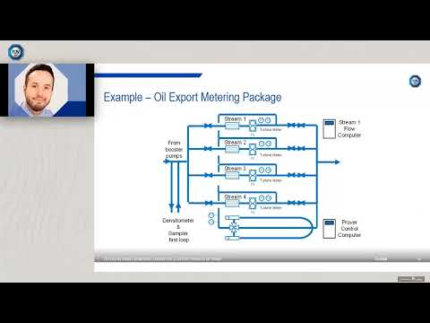
Webinar: Custody Transfer Metering — technology selection, metering system design, and measurement accuracy considerations for natural gas fiscal applications (TÜV SÜD)
Making the Right Meter Choice Today Protects Your Business Tomorrow
Your meter selection isn’t just a technical decision—it’s a business decision that affects your compliance status, your profitability, and your competitive position in ways that compound over years. A network of well-specified, properly installed, and rigorously maintained custody transfer meters produces defensible measurement records, minimal billing disputes, and clean regulatory audits. A network that was built on cost-minimized specifications and undermanaged maintenance produces the opposite—and the cumulative financial and reputational cost is consistently higher than the investment the better outcome would have required.
The framework in this guide—understand the regulatory requirements, select the right technology for each application, implement installation and maintenance standards that preserve compliance, and build management systems that keep the program sustainable over time—is the foundation for operating a natural gas distribution business that uses measurement excellence as a competitive asset rather than managing measurement deficiency as a persistent liability.
For distributors and agents who supply instrumentation to gas distribution companies, the ability to walk clients through this framework—and to supply the meters, documentation, and technical support that make it executable—is the value proposition that builds lasting, high-margin relationships in a market where product-only supply is increasingly commoditized.
Ready to Optimize Your Custody Transfer Measurement Program?
Download our Custody Transfer Meter Selection Checklist to evaluate your current meters against regulatory standards and identify optimization opportunities. Use it to assess each custody transfer point in your network—technology suitability, proving schedule status, documentation completeness, and ROI potential from upgrades.
Or schedule a consultation with the technical team at Инструменты "Нефритовый муравей to review your specific distribution network requirements. Our flow measurement engineers work with distributors and gas companies across multiple regulatory jurisdictions and can provide application-specific guidance on meter selection, certification requirements, and compliance program design.
Explore Jade Ant Instruments Flow Meter Solutions →
For deeper technical background, explore our related resources: Turbine vs. Ultrasonic Flow Meter Comparison | Hidden Cost of Flow Measurement Errors | Differential Pressure Flow Measurement Guide
External standards references: AGA Measurement Standards | API MPMS Chapter 14 | NIST Flow Calibration Services
Glossary of Key Technical Terms
Custody Transfer: Any flow measurement used at a point where ownership, billing responsibility, or contractual accountability for a fluid changes hands. Requires regulatory approval, traceable calibration, and audit-grade documentation.
AGA (American Gas Association): The primary standards body for natural gas measurement in North America. Key standards include AGA-3 (orifice), AGA-7 (turbine), and AGA-9 (ultrasonic).
NIST Traceability: The ability to link a meter’s calibration, through a documented and unbroken chain, to measurement standards maintained by the National Institute of Standards and Technology. Required for legally defensible custody transfer measurement records.
Type Approval: Regulatory certification that a specific meter model meets applicable performance standards. Allows any individual unit of that model to be installed in custody transfer service without individual testing.
Meter Proving: The process of comparing a custody transfer meter’s output against a reference standard of known accuracy to verify that the meter is performing within its specified tolerance. The primary mechanism for detecting measurement drift.
Meter Factor: The ratio of the reference volume (from the prover) to the indicated volume (from the meter) at a proving event. A meter factor outside the acceptable range indicates that the meter is drifting from its calibrated baseline.
Electronic Flow Computer (EFC): A purpose-built computing device that accepts inputs from the primary meter, pressure transmitter, and temperature transmitter and calculates reference-condition gas volume from actual-condition measurements. Must be type-approved and calibrated as part of the custody transfer system.
Коэффициент бета (β): For orifice meters, the ratio of the orifice bore diameter to the pipe internal diameter. Determines the differential pressure at a given flow rate and the meter’s sensitivity to upstream flow profile distortion.
Qmin, Qtransition, Qmax: The minimum, transition, and maximum flow rates that define the operating range of a custody transfer meter under its applicable standard. Different accuracy specifications apply in different parts of this range.
Straight-Pipe Run: The length of unobstructed, undisturbed pipe required upstream and downstream of a meter to ensure that the gas velocity profile meets the conditions assumed by the meter’s calibration. Specified in multiples of pipe diameter (D).
Часто задаваемые вопросы
1. What’s the difference between custody transfer and non-custody transfer flow meters?
Custody transfer meters measure gas at fiscal points where ownership or billing responsibility changes hands—they must meet strict accuracy standards (AGA-7 ±1% for turbine, AGA-9 ±0.7% for ultrasonic), carry valid regulatory approval, and produce audit-grade documentation. Non-custody meters are used for operational monitoring and process optimization; they have looser accuracy requirements (typically ±2–5% is acceptable) and no mandatory approval process. The distinction directly determines your certification requirements, proving obligations, and financial liability in the event of a billing dispute or regulatory audit. Installing a non-custody meter at a custody transfer point—even temporarily—creates a compliance violation that must be reported and remediated.
2. How often do custody transfer meters need to be calibrated or proven?
Proving frequency varies by regulatory jurisdiction and meter type. For turbine meters in high-volume service, annual proving is the typical baseline. For multipath ultrasonic meters with in-service diagnostic capability, biennial proving is increasingly accepted by state regulatory authorities. Rotary displacement meters serving commercial customers typically follow 3–5 year intervals specified by the state utility commission. The key principle is that the financial exposure at each custody transfer point—throughput volume multiplied by commodity value—should drive the proving interval: higher exposure justifies higher frequency. All proving events must be documented and records retained for the regulatory authority’s specified retention period, typically 5–10 years.
3. What does “NIST traceable” mean, and why do regulators care?
NIST (National Institute of Standards and Technology) traceability means your meter’s calibration can be linked, through a documented and unbroken chain of calibration comparisons, to measurement standards maintained by NIST. Each step in the chain has a documented calibration uncertainty. Regulators require NIST traceability because it provides independent, verifiable proof that your meters are measuring correctly—proof that doesn’t depend on your own assertion. Without NIST traceability, a meter’s calibration certificate is self-referential; it cannot be independently validated. In a billing dispute or regulatory audit, a measurement record produced by a meter with non-traceable calibration is legally vulnerable. Every custody transfer meter supplier should be able to provide calibration certificates that identify the laboratory, the reference standard used, and that standard’s traceability to NIST.
4. Can I use the same meter type across my entire distribution network?
Not necessarily, and standardizing on a single type is a risk if your network includes materially different operating conditions across stations. Different custody transfer points have different flow rates, operating pressures, gas compositions, and installation space constraints. A turbine meter that performs excellently at a high-volume, high-pressure transmission station may be chronically outside its linear range at a lower-volume commercial delivery point. A one-size-fits-all approach typically creates measurement problems at stations whose operating envelope falls outside the chosen meter’s optimum range. A practical middle ground is standardizing on a limited set of approved meter models—one turbine model for high-volume service, one ultrasonic model for medium-large stations, one rotary model for small commercial service—that collectively cover your network’s operating conditions without requiring a unique solution for each point.
5. What happens if my meter fails a regulatory audit?
The immediate consequences depend on the violation’s severity and your regulatory jurisdiction, but typically include: a formal non-compliance notice requiring a written response within 30 days, mandatory corrective action (meter replacement, proving, documentation remediation) within a specified timeframe, retroactive measurement correction covering the period from the last valid compliance record, and in serious cases, civil penalty proceedings. The practical business impact extends beyond the direct regulatory consequence: customers who become aware of a measurement non-compliance finding may file billing dispute claims covering the affected measurement period, and the finding affects your credibility in subsequent rate case proceedings and contract negotiations. Transparency—proactive self-reporting before an audit discovers the issue—is consistently treated more favorably than an audit finding and produces better regulatory outcomes.
6. How much does it cost to implement a proper custody transfer meter program?
Total program cost varies significantly with network size, meter types, and regulatory requirements, but a realistic framework for a 10-station regional distribution network includes: initial meter procurement and installation ($500,000–$1,500,000 depending on meter size and technology), annual proving and calibration program ($50,000–$200,000/year), metering management system and documentation ($20,000–$80,000 initial, $10,000–$30,000/year recurring), and regulatory compliance management ($30,000–$80,000/year including external technical support). The investment in a proper program consistently pays for itself within 2–4 years through improved billing accuracy, avoided regulatory penalties, and reduced billing dispute costs. The ROI case is strongest for networks with aging, under-maintained meter fleets where 1–3% systematic measurement errors are compounding across significant annual gas volumes.
7. What’s the difference between type approval and individual meter certification?
Type approval means a meter model has been tested and approved for custody transfer use—you can install any meter unit manufactured to the approved type without additional testing, provided quality documentation confirms the unit matches the approved design. Individual certification means a specific meter unit, identified by serial number, has been tested and certified—that approval applies only to that exact unit. Type approval is the operationally practical approach for distributors managing multiple meters, as it allows standardized procurement and avoids the delay and cost of individual testing for each unit. Individual certification makes sense for high-value flagship custody transfer points where the financial stakes justify the additional assurance of unit-specific testing, and for jurisdictions whose regulations specifically require individual certification rather than accepting type approval.
8. How do I know if my current meter supplier is properly certified?
Verify credentials directly—do not rely on the supplier’s representations without documentary evidence. The verification steps are: request the type approval certificate for the specific meter models offered for custody transfer service and confirm it is current and covers the relevant operating conditions; request the calibration laboratory’s ISO/IEC 17025 accreditation certificate and verify the scope covers flow measurement in the relevant range; check the calibration laboratory against the NIST NVLAP database for flow measurement calibration; and, for state-regulated applications, confirm the meter is listed as an approved type in your state regulatory authority’s approved products list or database. Suppliers who provide these documents without hesitation and whose credentials check out are qualified; those who are unable or unwilling to provide this documentation should not be used for custody transfer applications.
9. What gas composition factors affect custody transfer meter accuracy?
Gas composition affects different meter technologies differently. For ultrasonic meters, the speed of sound in the gas varies with composition, and if the flow computer’s composition input is stale or incorrect, the velocity-to-flow rate conversion introduces error. For turbine meters, gas density affects the meter factor at low flow rates, and significant composition variation (seasonal BTU changes, mixing of different gas sources) can shift the meter factor by 0.1–0.3% without any mechanical change. For orifice meters, gas density and compressibility factor variations affect the differential pressure calculation; an EFC using incorrect AGA-8 compressibility coefficients for the actual gas composition will produce systematic volume errors. The mitigation for all technologies is: install a gas chromatograph (GC) providing real-time composition data to the flow computer at custody transfer points where composition variability is significant, or document and prove the measurement uncertainty resulting from the composition variability is within acceptable limits.
10. Can I upgrade my meters without regulatory approval?
No. Any change to the equipment at a custody transfer point—meter replacement, EFC replacement or reprogramming, pressure or temperature instrument replacement—constitutes a measurement system change that requires regulatory notification and, in many jurisdictions, prior approval. Installing a new meter as a “temporary replacement” without notification is a compliance violation, even if the new meter is technically superior to the old one. Before any equipment change at a custody transfer station, contact your state regulatory authority, describe the proposed change, and obtain written confirmation of the required approval process. This step adds time to planned maintenance activities but protects against the significantly worse outcome of an audit finding for unauthorized meter modification.
11. What’s the financial impact of a 1% measurement error at a custody transfer point?
The annual financial impact is directly calculable from the station’s throughput and the commodity value. For a station delivering 1,500 MSCFD (million standard cubic feet per day) at $4.50/MSCF:
For a mid-sized distributor with 20 such stations, the network-wide annual exposure from a 1% fleet-wide accuracy gap is approximately $492,750/year. Over a 5-year proving interval on an aging turbine meter fleet where drift has reached 1.5% average, the cumulative billing exposure is roughly $2.5 million—recoverable through a meter upgrade program costing $800,000–$1,200,000 with a payback period under 2.5 years.
12. How do I manage compliance across multiple regulatory jurisdictions?
Build a centralized compliance matrix documenting, for each custody transfer station: regulatory jurisdiction, applicable measurement standard, required proving interval, last proving date, next required proving date, meter certification status, and any jurisdiction-specific requirements beyond the federal baseline. Standardize your practices to meet the most stringent requirements across all territories—a proving program that satisfies California CPUC will exceed minimum requirements in most other states. Use automated calendar tracking with escalating alerts to ensure no proving window is missed. When operating in a new jurisdiction, obtain the relevant measurement regulations directly from the state regulatory authority’s published rules before designing or modifying measurement systems—do not rely on a contractor’s representation of what the local requirements are.
13. What role does proper installation play in meter accuracy?
Installation is the single largest variable in custody transfer meter performance outside of meter technology selection itself. An orifice meter on a non-compliant meter tube with insufficient upstream straight-pipe run will produce systematic errors of 1–5% regardless of the quality of the orifice plate or differential pressure transmitter. A turbine meter installed with inadequate flow conditioning upstream of a severe elbow will produce errors of 2–4% that cannot be corrected through calibration because they are driven by the installation geometry, not the meter hardware. This is why certified installers and proper commissioning procedures are not optional costs—they are the steps that determine whether the meter you specified actually performs to its accuracy class in the field.
14. How do I choose between turbine, ultrasonic, orifice plate, and rotary displacement meters?
The selection follows from the operating requirements. Turbine meters are the established choice for moderate-to-high flow rates with stable, clean gas and where AGA-7 compliance is the required standard—strong accuracy performance with well-understood maintenance requirements. Multipath ultrasonic meters are preferred for new custody transfer installations where reduced maintenance cost, extended proving intervals, and AGA-9 compliance are priorities—higher initial cost, lower long-term operating cost. Orifice plate meters suit high-volume, high-pressure applications where the proven AGA-3 compliance record and composition-robustness are priorities—accept the pressure drop penalty in exchange for the most thoroughly validated measurement standard. Rotary displacement meters are the standard for lower-flow commercial and small industrial delivery points where their volumetric counting principle and straightforward proving are operationally practical. Refer to the TCO comparison table in this guide and match the technology to your specific flow range, pressure, and gas composition at each custody transfer point.
15. What should I do if I discover a meter accuracy problem during an audit?
Report it immediately and proactively to your regulatory authority—self-disclosure is treated more favorably than an auditor finding an unreported problem. The disclosure should include: the meter identification and location, the nature of the accuracy problem (what was found, when it was discovered), the estimated duration of the out-of-tolerance period (from the last valid proving to the present), and your preliminary estimate of the measurement error magnitude. Work with your meter supplier to quantify the error precisely and determine the affected billing periods. Develop a remediation plan covering: meter replacement or recalibration, retroactive billing reconciliation for affected accounts, documentation correction, and measures to prevent recurrence. Notify affected customers promptly and professionally. Transparency in this process protects your operating license and customer relationships far better than delayed disclosure—which regulators and customers interpret as concealment.
This guide was developed with technical input from the applications engineering team at Инструменты "Нефритовый муравей, a manufacturer and supplier of industrial flow measurement instrumentation for natural gas and industrial applications. For product specifications and application support, visit www.jadeantinstruments.com.
Key standards and external references: AGA Measurement Standards Library | API MPMS Chapter 14 | NIST Flow Calibration Service | PHMSA Pipeline Safety