Мировой рынок расходомеров объемом 12,14 млрд долларов США растет со скоростью 6,08 % CAGR и к 2034 году достигнет 19,46 млрд долларов США (Fortune Business Insights, 2026), на сам счетчик приходится примерно 30-40 % от общей стоимости измерительной системы. Остальные 60-70 % приходятся на проектирование, трубопроводы, проводку, ввод в эксплуатацию и техническое обслуживание - и все они зависят от одной вещи: насколько качественно вы установили счетчик.
Полевой аудит 2025 года, проведенный Турбины, Инк. обнаружил, что Более половины жалоб на точность расходомеров связаны с ошибками при установке, но не дефекты оборудования. Недостаточно прямая труба, обратное направление потока, запертый воздух, неправильная проводка - эти “простые” ошибки обходятся предприятиям в $18 000-$45 000 в год на одной 6-дюймовой линии, если учесть погрешность измерений, потери энергии и незапланированные остановки.
В этом руководстве собраны знания по установке, которые Инструменты "Нефритовый муравей инженеры создали 12 000 с лишним счетчиков, установленных в нефтегазовой, химической, водопроводной отраслях и системах отопления, вентиляции и кондиционирования воздуха. Независимо от того, устанавливаете ли вы накладной ультразвуковой счетчик на контур охлаждающей воды или вводите в эксплуатацию кориолисовый счетчик на салазках для передачи имущества, приведенные здесь принципы помогут вам избежать неприятностей.
1. Выбор правильного стиля установки: Встраиваемый, вставной, зажимной
Прежде чем резать трубу или сверлить отверстие под горячую воду, необходимо принять следующее решение как взаимодействие измерительного прибора с технологическим процессом. Каждый стиль накладывает свои ограничения по точности, стоимости и требованиям к отключению. A Руководство по выбору приборов Jade Ant Мы рассмотрим все пять факторов, но компромиссы, связанные с конкретной установкой, заслуживают отдельного сравнения.
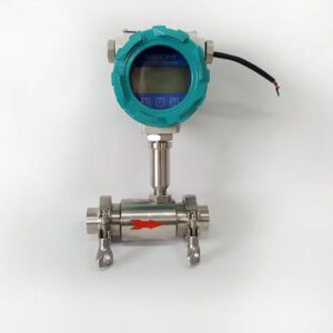
Каплеструйные (полнопроходные) расходомеры устанавливаются непосредственно в трубу, обеспечивая датчику полный контроль над участком измерения. Это устраняет неопределенность профиля, но требует остановки процесса для установки и демонтажа участка трубы. Врезные счетчики входят в трубу через одноточечный или многоточечный зонд, вставляемый через фитинг с горячим отводом, что означает возможность установки и извлечения зонда без остановки потока - основное преимущество для круглосуточных паровых коллекторов или крупных водопроводных магистралей. Компромисс заключается в том, что датчик берет образец профиля потока, а не всего сечения, что снижает точность с ±0,5 % (при установке в линию) до ±1,0-2,5 % (при вставке). Ультразвуковые измерительные приборы на хомутах крепятся снаружи, не проникая в трубу; они быстрее всего устанавливаются (менее 30 минут) и легче всего перемещаются, но их точность составляет от ±1,0 % до ±3,0 % в зависимости от состояния трубы и качества муфты.
Практическая иллюстрация: бумажной фабрике на юго-востоке США необходимо было измерить 14-дюймовый поток пара на коллекторе, который нельзя было отключать во время отопительного сезона. A вихревой вставной измеритель с выдвижным узлом был установлен через горячий кран менее чем за четыре часа. Точность измерений после ввода в эксплуатацию составила ±1,2 % от показаний, что вполне соответствует требованиям завода по энергетическому балансу ±2 %, а общая стоимость установки была на 40 % меньше, чем у вихревой линии, которая потребовала бы отключения на выходные, что обошлось бы в $85 000 потерянных производственных ресурсов.
Сравнительная таблица стилей установки
| Параметр | Рядовой (полнопроходной) | Вставка (горячее нажатие) | Ультразвуковой зажим |
|---|---|---|---|
| Типичная точность | ±0,2 %-±1,0 % показаний | ±1,0 %-±2,5 % показаний | ±1,0 %-±3,0 % показаний |
| Требуется остановка процесса? | Да (обрезки труб) | Нет (горячий штуцер) | Нет (внешнее крепление) |
| Время установки (6-дюймовая труба) | 4-8 часов | 2-4 часа | 0,5-1 час |
| Установленная стоимость (6 дюймов, долл. США) | $3,500–$12,000 | $2,000–$6,000 | $4,000–$10,000 |
| Размеры труб | ¼ дюйма-48 дюймов | 2 дюйма-120 дюймов | ½ дюйма-300 дюймов |
| Перемещаемый? | Нет | Частично (выдвижной зонд) | Да |
| Идеально подходит для | Передача товара при сдаче на хранение, высокая точность | Крупные трубопроводы, монтаж без остановки производства | Обследования, временный мониторинг |
| Перепад давления | Зависимые от технологий (низкий–умеренный уровень) | Незначительный (только зонд) | Ноль |
2. Требования к трубам с прямым ходом: наиболее часто нарушаемое правило
Для обеспечения номинальной точности любой измеритель, основанный на измерении скорости или перепада давления, требует наличия полностью сформированного симметричного профиля потока в зоне датчика. Помехи вверх по потоку — колена, переходники, клапаны, тройники — создают вихревые потоки и асимметрию, которые искажают показания. Универсальная сокращённая формула: “XD вверх по потоку / YD вниз по потоку”, где D — внутренний диаметр трубы.
Согласно Техническое описание установки Rosemount от компании Emerson и ISO 5167, требования к прямой прокладке зависят как от технологии, так и от типа входного фитинга. Ниже приведена практическая справочная таблица.
Требования к прямым участкам трубопровода в зависимости от типа счетчика и соединительного элемента, установленного выше по потоку
| Технологии измерительных приборов | Одиночный колено 90° (входной диаметр D / выходной диаметр D) | Два сгиба в разных плоскостях | Частично открытый задвижка | Редуктор / Расширитель |
|---|---|---|---|---|
| Электромагнитный | 5D / 3D | 10D / 3D | 10D / 5D | 5D / 3D |
| Vortex | 15D / 5D | 25D / 5D | 30D / 5D | 15D / 5D |
| Турбина | 10D / 5D | 20D / 5D | 25D / 5D | 10D / 5D |
| Ультразвуковой (по времени прохождения) | 10D / 5D | 20D / 5D | 30D / 5D | 10D / 5D |
| Диафрагма (β=0,6) | 16D / 6D | 34D / 6D | 44D / 6D | 5D / 6D |
| Кориолис | 0D / 0D * | 0D / 0D * | 0D / 0D * | 0D / 0D * |
| Тепловая масса (вставка) | 15D / 8D | 25D / 8D | 30D / 8D | 15D / 8D |
* Кориолисовые расходомеры измеряют массу напрямую и в значительной степени нечувствительны к нарушениям профиля потока; однако, Руководство по кориолисовым датчикам от Jade Ant Instruments рекомендует использовать 2D-проектирование на этапе разработки в качестве передовой практики для снижения механической вибрационной связи.

3. Ориентация, дренаж и предотвращение образования воздушных карманов
После прокладки прямого участка следующим важным фактором является ориентация. Установка измерительного прибора в неправильном положении относительно силы тяжести приводит к образованию воздушных пузырей (при работе с жидкостями) или скоплению конденсата (при работе с газом или паром), что в обоих случаях приводит к искажению измерительного сигнала. Общие правила, подтвержденные Рекомендации по прокладке трубопроводов от Cadillac Meter и Советы компании Jade Ant Instruments по использованию водомеров, представлены ниже.
При работе с жидкостями предпочтительным является монтаж на вертикальном трубопроводе с потоком, направленным вверх. Это позволяет поддерживать трубу заполненной и проталкивать пузырьки воздуха мимо датчика, не давая им скапливаться в корпусе расходомера. Если вертикальный монтаж невозможен, горизонтальный монтаж допустим только в том случае, если датчик (электроды для магниторезистивного расходомера, рассеивающая планка для вихревого расходомера) расположен ниже оси трубы — ни в коем случае не в положении «12 часов», где скапливается воздух. При измерении расхода газа и пара счетчик следует устанавливать горизонтально и обеспечить расположение сливных отверстий для конденсата ниже по потоку. Импульсные трубопроводы для разностных датчиков при измерении расхода пара должны иметь уклон вниз к счетчику, чтобы предотвратить засорение конденсатом.
На пищеперерабатывающем заводе в штате Висконсин в верхней части горизонтального участка контура CIP (очистка на месте) был установлен 3-дюймовый электромагнитный расходомер. В течение двух недель попадание воздуха из обратного трубопровода CIP приводило к завышению показаний расходомера на 8–12 % во время циклов слива. Поворот расходомера на 180°, так чтобы электроды оказались в положении «6 часов», и установка небольшого клапана сброса воздуха выше по потоку полностью устранили эту погрешность — устранение проблемы, которая обходилась в $1 200 в месяц из-за передозировки химикатов, заняло всего 30 минут.
4. Механический монтаж: фланцы, прокладки и момент затяжки
Даже при правильном направлении потока и правильной ориентации некачественное механическое соединение может привести к утечкам, напряжениям, вызванным несоосностью, или вдавливанию прокладки, что нарушает поток. Это Руководство ASME PCC-1 по болтовым фланцевым соединениям применяются непосредственно к установкам расходомеров. К ключевым правилам относятся следующие.
Всегда используйте прокладки того типа, который указан производителем измерительного прибора. Спирально-витые прокладки (нержавеющая сталь 304/графитовый наполнитель) являются стандартными для фланцевых измерительных приборов с давлением ANSI 150–600 при эксплуатации в технологических системах; кольцевые прокладки из EPDM или Viton подходят для санитарных соединений типа «три-кламп». Никогда не используйте старые прокладки повторно — прокладки, подвергшиеся остаточной деформации при сжатии, могут давать утечку уже при давлении, равном всего 50 % от первоначального усилие прижатия. Затягивайте болты по схеме «звездочка» (перекрестная затяжка) в три этапа: 30 % → 60 % → 100 % от конечного момента затяжки. Для 4-дюймового фланца ANSI 150 со спирально-витой прокладкой окончательный момент затяжки болтов для шпилек B7 обычно составляет 75–90 футов-фунтов.
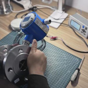
Не менее важное значение имеет выравнивание трубы. Если верхний и нижний фланцы не соосны с погрешностью не более 1/16 дюйма, корпус расходомера подвергается изгибающему напряжению, которое может привести к растрескиванию керамических вкладышей в магнитных расходомерах или деформации трубок Кориолиса. Перед затяжкой болтов проведите линейку по торцам фланцев и при необходимости подложите прокладки под трубные подвески для обеспечения выравнивания.
5. Электромонтаж, заземление и целостность сигнала
Даже идеально установленный и затянутый датчик будет выдавать некорректные данные, если электрическое соединение выполнено неправильно. В соответствии с рекомендациями InTek Flow и Руководство по техническим характеристикам приборов Jade Ant Instruments, ниже приведены основные правила электромонтажа.
Для аналогового выхода (4–20 мА) используйте кабель с витой экранированной парой (TSP), при этом экран должен быть заземлен только на стороне приемника. Соблюдайте расстояние не менее 12 дюймов (300 мм) от кабелей питания переменного тока напряжением свыше 120 В и не менее 24 дюймов от частотно-регулируемых приводов. Для связи по протоколу HART, наложенной на сигнал 4–20 мА, убедитесь в правильном сопротивлении контура (250–1 100 Ом) и избегайте Т-образных соединений в кабельной трассе, которые вызывают отражения сигнала. Длина кабелей импульсного выхода (с открытым коллектором) должна быть не более 100 м, чтобы избежать ухудшения качества сигнала; если длина кабеля превышает 30 м, используйте подтягивающие резисторы (1–10 кОм) на входе ПЛК.
Заземление имеет особое значение для электромагнитных расходомеров: жидкость должна находиться на том же электрическом потенциале, что и корпус расходомера. В случае металлических труб это обеспечивается за счет контакта с фланцем. На пластиковых или трубах с внутренним покрытием необходимо устанавливать заземляющие электроды или заземляющие кольца между прокладкой и фланцем трубы. Отсутствие заземления на водопроводной магистрали из ПВХ является самой распространённой причиной жалоб на “помехи в сигнале” — данные о выездах на место компании Jade Ant Instruments показывают, что на это приходится 23 % всех повторных вызовов, связанных с вводом в эксплуатацию магниторезистивных счётчиков.
6. Контрольный список для ввода в эксплуатацию: проверка нулевого расхода, проверка диапазона, проверка контура
Установка не считается завершённой, пока в трубопроводе не будет создано давление и на дисплее не появится число. В ходе ввода в эксплуатацию проверяется, что это число правильно. Структурированный контрольный список, адаптированный на основе Руководство по передовым методам компании Sierra Instruments должен включать следующие этапы.
Сначала проведите проверку нулевого расхода. При заполненном жидкостью трубопроводе и закрытых запорных клапанах как перед, так и после расходомера (подтвержден нулевой расход) показания расходомера должны составлять 0,0 ± значение, указанное в технических характеристиках производителя по стабильности нуля. Для кориолисового расходомера диаметром ½ дюйма это значение обычно составляет ±0,005 кг/мин; для магнитного расходомера диаметром 4 дюйма — ±0,01 м/с. Если показания дрейфуют, необходимо выполнить повторную нулевую настройку датчика. Во-вторых, проведите проверку диапазона измерения по эталону. При измерении расхода жидкости тест с использованием ведра и секундомера (для малых расходов) или сравнение с откалиброванным эталонным расходомером дают немедленную уверенность в точности. При измерении расхода газа стандартной процедурой является траверса Пито или сравнение с откалиброванным тепловым массовым расходомером. В-третьих, проверьте цепочку 4–20 мА от начала до конца, имитируя сигналы 4,00 мА (нулевой расход) и 20,00 мА (полная шкала) с датчика; убедитесь, что система DCS или ПЛК считывает правильное значение в инженерных единицах. В-четвертых, задокументируйте всё — серийный номер расходомера, фотографию ориентации при установке, показание при нулевом расходе, отклонение при проверке диапазона, результаты тестирования контура — в отчёте о вводе в эксплуатацию, который будет сопровождать объект в течение всего срока его службы.
Видео: Монтаж и ввод в эксплуатацию расходомера на практике
В этом видео подробно рассматриваются пять наиболее распространенных ошибок при монтаже — неправильное размещение, обратное направление потока, скопление воздуха, неправильная прокладка кабеля и отсутствие проверки нулевого уровня — с использованием видеоматериалов, снятых на объекте, и описанием действий по их устранению.
7. Семь самых дорогостоящих ошибок при монтаже (с указанием сумм убытков в долларах)
На основании полевых данных, полученных из Руководство по выбору измерительных компаний от Jade Ant Instruments, Топ-5 от Radical Techmart, а также на основе анализа ошибок, проведенного компанией Turbines Inc., в приведенной ниже таблице приведены количественные данные о самых дорогостоящих ошибках, с которыми сталкиваются инженеры на объекте.
Наиболее дорогостоящие ошибки при монтаже и их финансовые последствия
| # | Ошибка | Типичное снижение точности | Расчетная годовая стоимость (6-дюймовая линейка) | Основная причина |
|---|---|---|---|---|
| 1 | Недостаточная длина трубы прямого прохода | Ошибка от +3 % до +15 % | $8 000–$45 000 | Колено или клапан расположены слишком близко к входу |
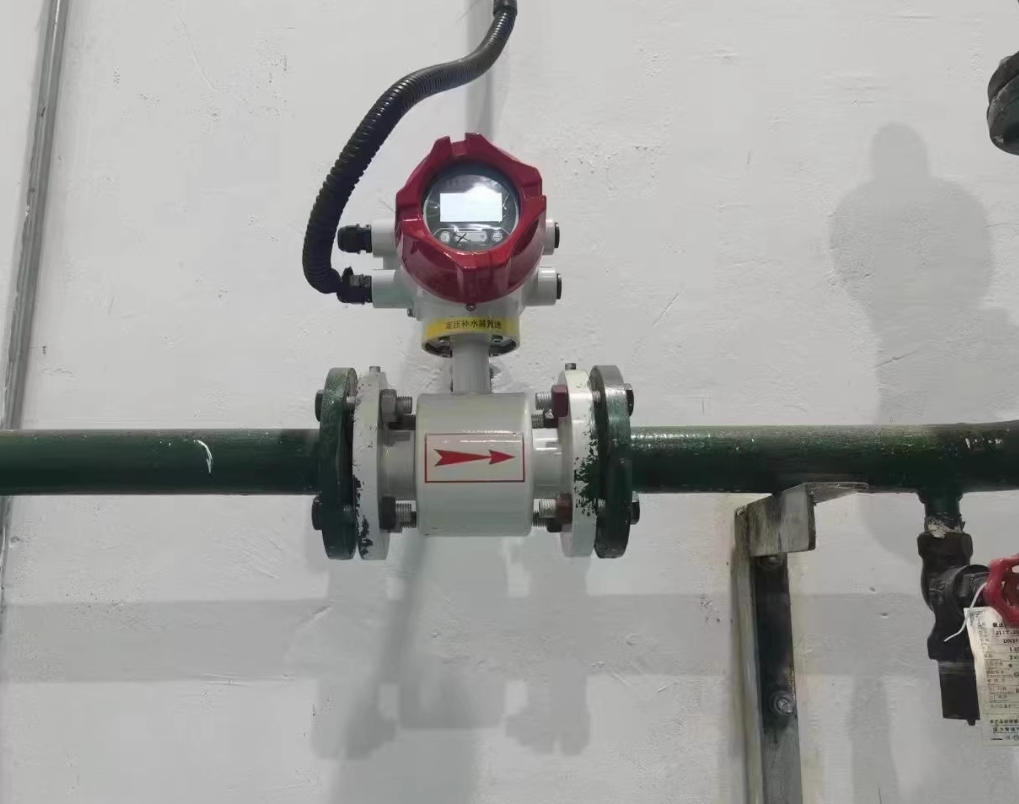
| 2 | Изменение направления потока | Полностью отрицательный или нестабильный | $5 000–$20 000 (потери при порционном отборе) | Стрелка на корпусе, которую не учли при установке |
| 3 | Застрявший воздух / пустая труба | Перечисление с +5 % до +25 % | $10 000–$30 000 | Расходомер на самой высокой точке трубопровода, без воздухоотводного клапана |
| 4 | Отсутствие заземления (магнитометры) | ±2 дрейф % + пики шума | $4 000–$12 000 | Пластиковая труба, без заземляющих колец |
| 5 | Счетчик увеличенного размера (для низкой скорости) | От +2 % до +8 % при низком расходе | $6 000–$18 000 | Расчет по размеру трубы, а не по расходу |
| 6 | Вибрационная муфта | Шум от ±1 % до ±5 % | $3 000–$15 000 | Расходомер, привинченный к трубе без опоры рядом с насосом |
| 7 | Пропуск проверки на отсутствие потока | Смещение от +0,5 % до +3 % | $2 000–$10 000 | Сокращение сроков ввода в эксплуатацию в условиях жестких сроков реализации проекта |
8. Общие затраты на техническое обслуживание за пять лет в разбивке по типам счетчиков
Установка — это разовое мероприятие, а техническое обслуживание — это долгосрочный процесс. В приведенной ниже таблице представлены типичные затраты на техническое обслуживание (рабочая сила + запчасти + калибровка) в течение 5 лет для 4-дюймового счетчика, эксплуатируемого в системе подачи чистой воды, на основе опубликованных данных из Pokcenser Tech, Турбины, Инк., а также сервисную документацию компании Jade Ant Instruments.
Общие затраты на техническое обслуживание за 5 лет (4 дюйма, чистая вода, долл. США)
Источники: Pokcenser Tech (2025), Turbines Inc. (2024), данные о выездном обслуживании компании Jade Ant Instruments (2024–2025). Обслуживание в условиях чистой воды; при использовании абразивных или коррозионных жидкостей затраты увеличиваются в 1,5–3 раза.
Электромагнитные и вихревые расходомеры занимают лидирующие позиции в сегменте оборудования, не требующего частого технического обслуживания, поскольку не имеют движущихся частей и датчиков, контактирующих с рабочей средой, подверженных износу. Турбинные расходомеры, несмотря на низкую стоимость приобретения, требуют наибольших затрат на техническое обслуживание в течение 5 лет из-за необходимости замены подшипников каждые 2–3 года и обязательной повторной калибровки после каждой замены. Кориолисовые расходомеры отличаются механической прочностью, но требуют периодических проверочных прогонов и периодической очистки трубок в условиях загрязненной среды. Диафрагмы требуют регулярных проверок остроты краев (каждые 12–24 месяца) и продувки импульсной линии.
9. Основные причины жалоб на точность после установки
Компания Jade Ant Instruments проанализировала 1 847 заявок на выездную техническую поддержку за период с 2023 по 2025 год и классифицировала основные причины каждой жалобы, связанной с точностью. Приведенное ниже распределение показывает, что причины, связанные с установкой, составляют более 60 % всех заявок, что еще раз подтверждает: правильная установка — это наиболее эффективная мера по улучшению, которую может принять операционная команда.
Основные причины жалоб на точность (n = 1 847 заявок)
Неправильная ориентация / Воздух — 18 %
Электрооборудование / Заземление — 15 %
Увеличенный счетчик — 10 %
Дрейф калибровки — 12 %
Изменение условий технологического процесса — 10 %
Прочее — 7 %
Источник: База данных по выездным обслуживаниям компании Jade Ant Instruments, 2023–2025 гг. (1 847 заявок в нефтегазовой, водной, химической отраслях и в сфере систем отопления, вентиляции и кондиционирования воздуха).
Три наиболее значимые причины — недостаточная длина прямой отрезки (28 %), неправильная ориентация или воздушные пузыри (18 %), а также проблемы с электрооборудованием и заземлением (15 %) — можно полностью предотвратить на этапе первоначальной установки. Если организация устранит только эти три категории, она избавится от 61 % жалоб на точность и избежит совокупной погрешности измерений, оцениваемой в $22 000–$68 000 в год, на типичном 20-метровом предприятии.
10. График технического обслуживания после установки
После ввода в эксплуатацию для каждой технологии учета действует свой график технического обслуживания. В приведенной ниже таблице представлен сводный график, который Инструменты "Нефритовый муравей рекомендует своим клиентам в качестве ориентира; интервалы следует сокращать при работе с загрязнёнными или абразивными жидкостями и увеличивать — при работе с чистыми, стабильными жидкостями.
| Задача | Электромагнитный | Vortex | Ультразвуковой (накладной) | Турбина | Кориолис | Дроссель / Перепад давления |
|---|---|---|---|---|---|---|
| Визуальный осмотр | 6 месяцев | 6 месяцев | 6 месяцев | 3 месяца | 6 месяцев | 3 месяца |
| Проверка нулевого расхода | 12 месяцев | 12 месяцев | 12 месяцев | 6 месяцев | 12 месяцев | 12 месяцев |
| Полная калибровка | 3–5 лет | 3–5 лет | 2–3 года | 1–2 года | 3–5 лет | 2–3 года |
| Очистка датчика / элемента | 12–24 месяцев | 24 месяца | 12 месяцев (гель для соединения) | 6–12 месяцев | 12–24 месяцев | 12 месяцев (импульсные линии) |
| Замена движущихся деталей | Н/Д | Н/Д | Н/Д | 2–3 года (подшипники) | Н/Д | Не применимо (при износе заменить пластину) |
| Типичный срок службы | 15–25 лет | 15–20 лет | 10–15 лет | 5–10 лет | 15–25 лет | 10–15 лет (пластина) |
11. Матрица выбора: какой измерительный прибор и какой способ установки подойдут для ваших задач?
Подводя итог, в приведенной ниже таблице представлены соотношения между типичными сценариями применения и рекомендуемыми технологиями учета и способами установки. Эти комбинации отражают общее мнение, сформированное на основе Методология отбора по 5 факторам компании Jade Ant Instruments, Сравнение 7 типов Supmea, а также стандарты ISO 5167 и ASME MFC.
| Заявка | Рекомендуемые технологии | Тип монтажа | Важное примечание по установке |
|---|---|---|---|
| Учет нефти и газа при передаче из хранилища | Кориолис или турбина | В строке | Нулевой прямой пробег (эффект Кориолиса) или 10D/5D (турбинный); соответствие стандарту OIML R117 |
| Муниципальное водоснабжение | Электромагнитный | В строке | 5D/3D; заземляющие кольца на кабелях из ПВХ; степень защиты IP68 для подземных колодцев |
| Учет энергии пара | Вихрь (многомерный) | В строке или вставкой | 15D/5D; горизонтальная установка; слив конденсата вниз по потоку |
| Контур охлажденной воды системы ОВКВ | Ультразвуковой (накладной) | Накладной | 10D/5D; очистка внешней поверхности трубы; проверка герметичности муфты каждые 12 месяцев |
| Аудит систем сжатого воздуха | Тепловая масса (встраиваемая) | Ввод (метод «горячего подключения») | 15D/8D; выдвижной зонд; рекомендуется установить осушитель перед устройством |
| Сточные воды / шлам | Электромагнитный (с PTFE-покрытием) | В строке | 5D/3D; предпочтительно вертикальный восходящий поток; закаленные электроды (Hastelloy C) |
| Пакетное дозирование (фармацевтика/пищевая промышленность) | Кориолис | В строке | Ориентация сливного отверстия для CIP; санитарные фитинги Tri-Clamp; проверка на нулевое давление перед каждой партией |
Установка — это мультипликатор
Неправильно установленный счетчик $5 000 показывает худшие показатели, чем правильно установленный счетчик $1 500. Данные, приведенные в данном руководстве, наглядно подтверждают этот факт: 61% жалоб на точность приборов % связано с тремя ошибками при установке, которых можно было избежать, а разница в затратах на техническое обслуживание за 5 лет между технологиями с наименьшей и наибольшей стоимостью составляет 5×. Меры, обеспечивающие наибольшую рентабельность инвестиций (ROI), которые может принять любое предприятие, — это потратить дополнительно 2–4 часа во время монтажа на надлежащую проверку прямолинейности, проверку ориентации, соблюдение процедур затяжки, экранирование проводки и составление протокола ввода в эксплуатацию.
Если вы планируете новую установку или устраняете неисправности в существующей системе, Инструменты "Нефритовый муравей предлагает бесплатные консультации по проверке монтажа, в ходе которых наши инженеры оценивают изометрические чертежи трубопроводов, дают рекомендации по размещению измерительных приборов и предоставляют контрольный список для ввода в эксплуатацию, разработанный с учетом особенностей вашей технологии и сферы применения. Начните с нашего руководства по выбору, основанного на 5 факторах или научитесь правильно интерпретировать технические характеристики вашего измерительного прибора чтобы у вас была надлежащая основа ещё до того, как будет сделан первый поворот гаечного ключа.
Часто задаваемые вопросы (FAQ)
Вопрос 1: Каково самое важное правило при монтаже расходомера?
Обеспечение достаточного участка трубы с прямым ходом перед и после расходомера. Для большинства расходомеров, основанных на измерении скорости (вихревых, турбинных, ультразвуковых), общее правило гласит: не менее 10 диаметров трубы перед расходомером и 5 диаметров после него после одного колена 90°. Недостаточный прямой участок трубопровода является основной причиной жалоб на точность измерений после установки, на которую приходится 28 % заявок на выезд сервисной службы, согласно Инструменты "Нефритовый муравей данные.
Вопрос 2: Можно ли установить расходомер без остановки технологического процесса?
Да — вставные расходомеры и ультразвуковые расходомеры с зажимным креплением позволяют осуществлять монтаж без остановки технологического процесса. При установке вставных расходомеров используется фитинг для монтажа «на горячую» и выдвижной зонд; монтаж занимает 2–4 часа. Ультразвуковые расходомеры с зажимным креплением монтируются снаружи за менее чем час. Для установки проходных (полнопоточных) расходомеров всегда требуется остановка технологического процесса и демонтаж участка трубопровода.
Вопрос 3: Требуется ли для кориолисового расходомера прямой участок трубопровода?
Кориолисовые расходомеры измеряют массу напрямую и в значительной степени нечувствительны к нарушениям профиля потока, поэтому производители обычно указывают прямой участок 0D/0D. Однако, В соответствии с передовой практикой рекомендуется использовать 2D-анализ вверх по течению для минимизации вибрационной связи со соседними фитингами, особенно в системах с трубами большого диаметра (4 дюйма и более).
Вопрос 4: Что произойдет, если установить магниторезистивный расходомер на пластиковую трубу без заземления?
При отсутствии пути заземления потенциал жидкости колеблется относительно электродов измерительного прибора, что приводит к появлению шумов в измерениях, дрейфу базовой линии на ±2 % и более, а также к периодическим скачкам сигнала. Решением этой проблемы является установка заземляющих колец (или заземляющих электродов, встроенных в измерительный прибор) между фланцами. Это третья по частоте ошибка монтажа, на которую приходится 15 % жалоб, связанных с точностью измерений.
Вопрос 5: Как часто следует проводить повторную калибровку расходомера после его установки?
Частота калибровки зависит от технологии и степени критичности. В качестве ориентира: электромагнитные и вихревые расходомеры — каждые 3–5 лет, ультразвуковые и диафрагменные расходомеры — каждые 2–3 года, а турбинные расходомеры — каждые 1–2 года в связи с износом подшипников. Для коммерческого учета ежегодная калибровка является отраслевым стандартом в соответствии с Технический документ компании «Эндресс+Хаузер» по управлению калибровкой.
Вопрос 6: Что такое устройство подготовки потока и в каких случаях оно необходимо?
Устройство выравнивания потока — это устройство (в виде пучка труб, перфорированной пластины или ребер), устанавливаемое перед расходомером для выпрямления и симметризации профиля потока. Он необходим, когда доступный прямой участок трубопровода меньше минимального требования расходомера — например, когда после двойного колена имеется только 8D, а вихревой расходомер требует 25D. Устройство для выравнивания потока позволяет сократить фактическое необходимое расстояние до примерно 3D + устройство + 3D, при этом его стоимость составляет от $800 до $3,500 в зависимости от размера.
Вопрос 7: На какой трубе следует устанавливать расходомер — на вертикальной или на горизонтальной?
При работе с жидкостями предпочтительна вертикальная установка с восходящим потоком, так как при этом труба остается заполненной, а воздух проходит мимо датчика. Для газа или пара стандартной является горизонтальная ориентация с конденсатоотводчиками, расположенными ниже по потоку. Наименее удачным является горизонтальное расположение с датчиком в положении «12 часов» (в верхней части трубы), при котором при работе с жидкостью скапливаются пузырьки воздуха, что приводит к погрешностям показаний в пределах 5–25 %.
Вопрос 8: Сколько стоит типичная установка промышленного расходомера?
Для встроенного счетчика диаметром 4–6 дюймов на стандартном технологическом предприятии типичная полная стоимость монтажа (счетчик + оплата труда + фитинги + электромонтаж + ввод в эксплуатацию) составляет от $3 500 до $12 000. Вставные расходомеры позволяют снизить эти затраты до $2 000–$6 000 за счет отсутствия необходимости в разрезании трубы. Ультразвуковые приборы с зажимным креплением стоят от $4 000 до $10 000, включая сам прибор, но обеспечивают самую быструю окупаемость при использовании для энергетического аудита. Эти цифры основаны на ценах компании Jade Ant Instruments на 2025–2026 годы и результатах отраслевых опросов.
Вопрос 9: Может ли вибрация от расположенных поблизости насосов повредить расходомер?
Да. Механические колебания, возникающие от насосов, компрессоров или резонанса трубопроводов, могут повредить чувствительные компоненты (ультразвуковые датчики, трубки Кориолиса) и привести к появлению помех в измерительном сигнале. InTek Flow рекомендуется устанавливать расходомер на расстоянии не менее 5D от любого источника вибрации и, при необходимости, использовать гибкие соединительные элементы или виброизолирующие крепления. Вихревые расходомеры особенно уязвимы, поскольку внешняя вибрация может имитировать частоты образования вихрей.
Вопрос 10: Где можно получить профессиональную помощь по установке расходомера?
Инструменты "Нефритовый муравей предоставляет бесплатные консультации по проверке проектов, включая планировку трубопроводов, размещение счетчиков, схемы электроподключения и контрольные списки для ввода в эксплуатацию. Для получения дополнительных рекомендаций обратитесь к Инструкции по установке от компании Tameson, Блог компании Sierra Instruments, посвящённый оптимизации, а также руководство по установке от производителя вашего счетчика.
Ссылки: Fortune Business Insights (2026) — Отчет о рынке расходомеров; Turbines, Inc. (2025) — Распространенные ошибки при работе с расходомерами; Sierra Instruments (2024) — Оптимизация монтажа; Emerson Rosemount (2025) — Руководство по ориентации при монтаже (PDS); ISO 5167 — Измерение расхода жидкости с помощью устройств, основанных на перепаде давления; ASME PCC-1 — Руководство по болтовым фланцевым соединениям; Jade Ant Instruments (2023–2025) — База данных по техническому обслуживанию на месте; Pokcenser Tech (2025) — Сравнение затрат на техническое обслуживание; Cadillac Meter — Требования к трубопроводам; Tameson — Руководство по монтажу расходомеров; InTek Flow — Распространенные ошибки при работе с расходомерами и способы их устранения; Endress+Hauser — Технический документ по управлению калибровкой расходомеров.