How to Diagnose Gas Meter Flow Problems in Your Facility: A Technical Guide for Industrial Stakeholders
Executive Summary: Why This Matters to Your Operation Right Now
A 2% measurement error on a 10,000 MMBtu/month industrial gas supply account costs roughly $6,000 to $12,000 per month in billing discrepancy — $72,000 to $144,000 per year — before any process efficiency losses are factored in. That number comes from a straightforward calculation: a mid-sized industrial user paying $3–$6/MMBtu, operating with a meter that has drifted by two percentage points since its last calibration.
For OEM skid-mount manufacturers, EPC project teams, instrument distributors, MRO maintenance departments, and municipal utility operators, unresolved gas meter flow problems don’t stay in the metering room. They escalate into billing disputes, failed commissioning audits, process upsets, and — in custody transfer applications — contract claims.
Here is the core insight that this guide builds on: research and field experience consistently show that approximately 70% of reported gas meter failures are not meter failures at all. They are installation errors, environmental factors, configuration mistakes, or compensation system faults — problems that a structured diagnostic process can identify and resolve without meter replacement.
This guide delivers that diagnostic framework. It is written specifically for engineering and procurement professionals who need to resolve flow measurement problems fast, protect project timelines, and build the internal technical capability to prevent recurrence.
📌 Glossary note: Technical terms are defined on first use throughout this guide. A full glossary appears at the end.
What Gas Meter Flow Actually Measures — And Where It Goes Wrong
Before diagnosing a problem, it helps to be precise about what the meter is actually doing.
A gas flow meter measures the volume or mass of gas passing through a cross-section of pipe per unit of time. The measurement unit depends on the technology and application:
- Volumetric flow (e.g., m³/h, ACFM — Actual Cubic Feet per Minute) measures gas volume at actual operating temperature and pressure. It changes when pressure or temperature changes, even if the actual quantity of gas molecules doesn’t.
- Corrected volumetric flow (e.g., Nm³/h — Normal cubic meters per hour at 0°C and 1 atm; SCFM — Standard Cubic Feet per Minute at 60°F and 14.7 psia) adjusts the raw volume measurement to a standard reference condition, making it comparable across different operating pressures and temperatures.
- Mass flow (e.g., kg/h, lb/h) measures actual mass throughput directly, independent of temperature and pressure. It is the most accurate representation of “how much gas actually moved” — which is why thermal mass flow meters and Coriolis meters are preferred for billing, emissions reporting, and process control.
Why This Distinction Matters for Diagnosis
If your meter reports volumetric flow without proper temperature and pressure compensation, and your supplier invoices on a corrected or mass flow basis, you will see a measurement discrepancy every time operating conditions deviate from the calibration reference — even if both meters are working perfectly.
A 30% swing in line pressure produces approximately a 30% error in an uncompensated volumetric reading. A 20°C temperature difference between summer and winter introduces a roughly 7% measurement variation in uncomepensated systems.
This is the most commonly overlooked source of gas meter discrepancy in industrial facilities. Check compensation configuration before investigating meter hardware.
Section 2: The 10-Step Diagnostic Framework for Gas Flow Anomalies
A repeatable diagnostic process cuts resolution time by 60–70% and prevents the most common error: fixing symptoms while missing root causes.
This framework applies regardless of meter technology. Work through each step in sequence. Document your findings at every stage — that documentation becomes your audit trail and your supplier escalation evidence.
Step 1: Verify Flow Profile Consistency
Check upstream and downstream pressure readings at their normal operating values. Look for signs of pulsation — rapid, rhythmic pressure fluctuations originating from reciprocating compressors, control valves, or pump cycling.
Pulsation is one of the most destructive and least visible causes of gas meter inaccuracy. Research published in Flow Measurement and Instrumentation (Rahmati, 2024) documents that flow pulsations of large amplitude can cause turbine gas meter errors of 50–80% — not a rounding error, a measurement catastrophe. Vortex meters show mainly negative errors under pulsating conditions, especially at “lock-in” when pulsation frequency approaches the vortex shedding frequency.
What to check:
- Install a pressure recorder upstream and downstream for 24–48 hours
- Look for pressure oscillations with frequency between 0.5–20 Hz (characteristic of reciprocating compressors)
- If pulsation is confirmed, the meter technology may not be appropriate for the installation — turbine and vortex meters are the most affected; ultrasonic multipath meters are the most pulsation-resistant
Step 2: Validate Meter Installation Compliance
Gas flow meters need a section of straight, unobstructed pipe upstream and downstream to ensure the gas velocity profile is fully developed before reaching the measurement point. If an elbow, valve, tee, or reducer is too close to the meter inlet, the velocity profile is distorted — and the meter’s measurement of local velocity no longer represents the true average across the pipe.
| Tipo de medidor | Minimum Upstream Straight Run | Minimum Downstream Straight Run |
|---|---|---|
| Turbine (single elbow) | 10 × pipe diameter (D) | 5D |
| Turbine (double elbow out-of-plane) | 20D | 5D |
| Ultrasonic (2-path) | 10D | 5D |
| Ultrasonic (multipath) | 5D | 3D |
| Vórtice | 15–20D | 5D |
| Massa térmica (inserção) | 20D | 10D |
| Coriolis | 0–2D (generally insensitive) | 0–2D |
Source: Industrial Monitor Direct, Flow Meter Straight Run Requirements Technical Reference
Verify that the installed piping configuration matches these requirements. No amount of recalibration can correct systematic error caused by a non-compliant installation.
Step 3: Assess Meter Type vs. Application Match
Confirm whether the installed meter technology is appropriate for the gas composition, flow range, operating pressure, and process conditions. This is a step many teams skip because “the meter was specified at project design” — but operating conditions change, and original specifications are not always implemented correctly in the field.
| Tecnologia de medidores | Best Application | Known Weakness |
|---|---|---|
| Turbina | Clean, dry gas; custody transfer; stable high flow | Bearing wear; sensitive to liquid carryover and pulsation |
| Ultrassônico (tempo de trânsito) | Wide range; custody transfer; bidirectional; high pressure | Fouling on transducer faces; low-flow below cutoff |
| Thermal mass | Low flow; gas consumption monitoring; direct mass flow | Sensitive to gas composition changes; requires clean gas |
| Diaphragm | Residential/commercial; low pressure | Not suitable for high-flow industrial; condensate damage |
| Vórtice | High-temperature steam and gas; clean service | External vibration interference; low-flow cutoff issues |
| Coriolis | High-value custody transfer; direct mass flow; corrosive gas | High cost; pressure drop; size limitations |
If the installed technology doesn’t match the actual operating conditions, the corrective action is re-specification — not repeated calibration.
Step 4: Inspect for Contamination or Obstruction
Physical contamination inside the meter body or on sensor surfaces is the most immediately resolvable failure category.
Common contaminants by gas system type:
- Natural gas systems: Pipe scale (iron oxide), compressor oil aerosols, hydrocarbon condensate during cold snaps
- Compressed air systems: Compressor oil carry-over, water condensate, rust from carbon steel upstream piping
- Biogas systems: Hydrogen sulfide deposits, siloxane compounds (particularly damaging to thermal sensors), moisture
- LPG/propane systems: Residual liquid, lubricant from regulators
How to inspect safely: The meter must be properly isolated, depressurized, purged, and gas-freed per your site’s Lock-Out/Tag-Out procedure before any internal access. Non-negotiable.
A sudden drop to near-zero reading in an otherwise stable system is almost always an obstruction event — not a sensor failure or calibration drift, both of which develop gradually.
Step 5: Evaluate Signal Output and Communication Integrity
Before concluding that the meter’s measurement is wrong, verify that the signal leaving the meter is being correctly received and interpreted by the receiving system.
Test the output signal directly at the meter terminals:
- 4–20 mA output: Use a calibrated loop calibrator (a handheld instrument that measures and sources current loop signals) to verify the output current against the displayed flow reading. A meter showing 50% of full scale should output exactly 12.0 mA. Discrepancy between displayed value and output current points to an output circuit fault, not a measurement fault.
- Pulse output: Count pulses per unit time with an independent counter and verify against the meter’s flow display using the programmed K-factor (the calibration constant, expressed as pulses per unit volume, that converts raw pulse count to flow rate).
- HART/Modbus digital: Read the primary variable directly from the digital output and compare to the local display. HART (Highway Addressable Remote Transducer — a protocol that overlays digital data on the standard 4–20 mA signal) diagnostics can reveal additional fault codes not visible on the local display.
Also check:
- Earth/ground continuity at the meter housing (poor grounding causes EMI pickup — see Section 3)
- Cable shielding integrity, particularly near variable-speed drives and welding equipment
- Conduit seal condition — moisture ingress is a leading cause of intermittent signal faults in outdoor installations
Step 6: Audit Calibration History and Drift
Pull the meter’s calibration record and establish the facts before forming a hypothesis:
- When was the last calibration performed?
- What was the “as-found” deviation at the last calibration (how far was it out before adjustment)?
- Has the calibration interval been followed per the manufacturer’s recommendation and regulatory requirements?
- Is the current reading discrepancy consistent with the drift rate observed at the last calibration?
Industry guidance on calibration intervals:
| Tipo de aplicativo | Recommended Calibration Interval |
|---|---|
| Custody transfer / fiscal metering | 6–12 months (AGA, API MPMS requirement) |
| Process control (billing quality) | 12-24 meses |
| General utility monitoring | 24 a 36 meses |
| Low-criticality consumption monitoring | Up to 5 years if meter diagnostics confirm stability |
Note: High-contamination applications (biomethane, compressed air, wet gas) warrant intervals 50% shorter than the above.
If no calibration records exist, treat the meter as uncalibrated and begin from baseline — request manufacturer recalibration with “as-found” documentation before any adjustment.
Step 7: Check Secondary Devices and Transmitters
The gas flow meter is rarely the only instrument in the measurement chain. Flow computers (electronic devices that calculate corrected or totalized flow from raw meter signals plus temperature and pressure inputs), pressure transmitters (PTs)e resistance temperature detectors (RTDs) all contribute to the final reported value.
A perfectly accurate flow meter reporting into a flow computer with a drifted pressure transmitter will produce a systematically incorrect corrected flow — even though the flow meter itself is performing correctly.
Check each secondary device independently:
- Verify PT reading against a calibrated reference pressure gauge at the same tap point
- Verify RTD reading against a calibrated reference thermometer at the same location
- Confirm flow computer configuration matches current meter K-factor, gas composition, and reference condition settings
Step 8: Analyze Historical Flow Data Trends
Modern SCADA systems (Supervisory Control and Data Acquisition — software platforms that monitor and log process data from field instruments) store months or years of flow history. That data is one of the most powerful diagnostic tools available.
Patterns to look for in trend data:
| Trend Pattern | Most Likely Cause |
|---|---|
| Gradual, consistent downward drift over months | Calibration drift or progressive sensor contamination |
| Step-change drop to a lower stable value | Physical obstruction event or configuration change |
| Increased variability / noise in reading | Ground loop, EMI, or mechanical vibration onset |
| Seasonal highs and lows correlated with temperature | Compensation system failure or uncompensated measurement |
| Reading discrepancy that appears only at high flow | Linearization error, range configuration issue |
| Reading discrepancy that appears only at low flow | Below-minimum-flow-rate cutoff or zero-point drift |
Comparing the current trend against the baseline trend from the first three months after commissioning will often reveal exactly when and how quickly the deviation developed — which is valuable evidence for root cause determination.
Step 9: Perform Bypass or Parallel Flow Verification
When diagnostic steps 1–8 have not identified a definitive root cause, the most reliable next step is a side-by-side measurement using an independent calibrated reference.
Options:
- Clamp-on portable ultrasonic meter on the same pipe section (no process interruption required). Accuracy is typically ±1–2%, sufficient to identify discrepancies greater than that threshold.
- Master meter in bypass — a calibrated meter installed in a parallel bypass leg that allows flow to be diverted through the reference meter for direct comparison. This approach is standard in custody transfer verification programs.
- Mobile proving unit (used by utility companies for high-value measurement points) — a calibrated positive displacement prover that provides the highest-accuracy reference measurement.
Document the comparison measurement conditions: flow rate, pressure, temperature, gas composition, and duration. A comparison measurement taken over less than 30 minutes in unstable flow conditions has limited diagnostic value. A 2-hour comparison during stable, mid-range operating conditions is definitive.
Step 10: Document Findings and Define Root Cause
A diagnostic process without documentation is a troubleshooting exercise. With documentation, it becomes an organizational asset.
Minimum documentation for each diagnostic engagement:
- Meter identification: model, serial number, installation tag, location
- Problem as reported by the customer or operations team
- Diagnostic steps performed, dates, and measured results at each step
- Root cause determination with supporting evidence
- Corrective action taken and verified outcome
- Next scheduled calibration or inspection date
- Technician name and qualifications
This record protects against warranty disputes, demonstrates due diligence in regulatory audits, and provides the data for trending across your installed meter population — identifying which applications, meter types, or site conditions generate the highest service demand.
Operational Causes to Investigate Before Replacing Equipment
Contamination on thermal mass flow meter sensors develops gradually — customers often attribute the slow measurement decline to process changes rather than sensor degradation until the discrepancy becomes too large to ignore.
Industry field data from power engineering publications and gas measurement specialists consistently documents that errors exceeding 20% have been observed in real installations — not from catastrophic meter failure, but from environmental and installation factors that accumulate undetected.
Here are the most common operational causes to investigate and eliminate before recommending equipment replacement:
Improper Piping Geometry — The absence of adequate upstream straight-run piping is the single most common installation error. It produces systematic error from day one that cannot be corrected by recalibration. Verify against manufacturer specifications for every meter type.
Wet Gas and Liquid Carryover — Natural gas at reduced ambient temperatures, compressed air systems without adequate drying, and biogas streams all carry the risk of liquid dropout. Condensate coating turbine rotor bearings, diaphragm meter internals, or ultrasonic transducer faces alters measurement characteristics without triggering visible alarms. In high-value measurement applications, process vision technologies and liquid detection sensors upstream of the meter are worth specifying.
Vibration from Pumps and Compressors — Vortex flow meters are the most vibration-sensitive technology. If a vortex meter is installed within 3–5 pipe diameters of a reciprocating compressor flange or on a poorly supported run of pipe, the mechanical vibration frequency may couple into the vortex sensing element, producing phantom flow readings even at zero flow. Diagnose this by observing the meter during a verified zero-flow condition (with process isolated upstream and downstream). If the meter reads non-zero, external vibration excitation is the cause.
Temperature and Pressure Compensation Errors — Incorrect reference conditions programmed in the flow computer, a failed pressure transmitter, or a drifted RTD feeding incorrect input to the compensation calculation can each produce systematic billing error with no visible meter fault. A meter accurately measuring actual volumetric flow but converting to standard conditions using wrong pressure input will produce a linearly scaled error equal to the pressure offset as a percentage of absolute pressure.
Control Valve Interactions — A control valve cycling rapidly immediately downstream of a gas flow meter creates localized pressure fluctuations that disturb the flow profile and introduce measurement noise. In severe cases, partial valve closure can create cavitation-like conditions in gas lines that physically stress meter internals. Specify a minimum distance of 5D between any control valve and the meter outlet connection.
Electrical Ground Loops and EMI — Variable-speed drives (also called variable-frequency drives — power electronics that control motor speed by varying electrical frequency) generate significant electromagnetic interference (EMI) that can couple into the signal cables of nearby gas flow meters. The diagnostic signature is a characteristic oscillation in the displayed reading — often at 50 Hz or 60 Hz mains frequency — that cannot be resolved by any adjustment to the meter itself. The fix is proper cable shielding, a dedicated earth ground for the meter, and physical separation of signal cables from power cables.
Incorrect K-Factor or Configuration Settings After Firmware Updates — Firmware updates (software upgrades to the meter’s internal operating system) occasionally reset configuration parameters to factory defaults. The K-factor — the calibration constant that converts raw pulse or frequency output to engineering units — must be verified after every firmware update. A K-factor error of even 1% produces a 1% systematic billing error across all flow conditions.
Technology-Specific Diagnostics for Your Application
For OEM Equipment and Skid-Mount Manufacturers
Your liability exposure from gas meter problems is front-loaded at commissioning. A skid delivered with an incorrectly specified meter, an installation that doesn’t meet straight-run requirements, or a flow computer configured with the wrong gas composition creates a problem that shows up during the customer’s Site Acceptance Test — the worst possible moment.
Design for diagnosability:
- Integrate test ports (plugged tee connections) immediately upstream and downstream of each meter for future reference pressure measurement
- Specify isolation valves with bypass to allow meter removal and reference meter installation without process shutdown
- Require meters with diagnostic output — signal quality indicators, sensor health flags, and alarm contacts — rather than meters with only flow output
- Standardize installation templates across all skid designs to eliminate project-to-project installation variation
Explore the full flow meter selection framework at the Guia de seleção de medidores de vazão da Jade Ant Instruments to match meter technology to your specific gas type, pressure rating, and process conditions at the design stage — before fabrication begins.
For EPC and System Integration Teams
The most expensive gas meter problem for an EPC firm is the one that appears during commissioning. Design-phase specification errors discovered at Site Acceptance Testing cost 10–100 times more to correct than the same error caught at FEED review.
Commissioning and handover best practices:
- Include flow meter configuration verification as a mandatory step in your Site Acceptance Test protocol — confirm K-factor, gas type, reference conditions, and engineering unit settings against the approved data sheet
- Validate the output signal chain end-to-end: meter terminal → cable → marshalling → DCS input card → SCADA tag → historian. A discrepancy at any point produces a measurement error that doesn’t belong to the meter
- Provide as-commissioned configuration backups for every meter as part of project handover documentation — this is the configuration record that protects both you and the client if a future firmware update resets settings
For Utility and Municipal Gas Providers
For utilities managing large distribution networks, the diagnostic challenge is scale. A 1% measurement error on a single 10,000 MMBtu/month industrial customer is significant. Multiplied across a zone of 50 high-volume accounts using meters of similar age and installation vintage, the revenue exposure is material.
Zone-level diagnostic approach:
- Implement routine flow meter health audits across distribution zones on a staggered schedule — not all at once, but rolling monthly so that no segment goes more than 12 months without an inspection
- Use mobile verification units (portable calibrated reference meters that can be clamped or inserted at each customer’s metering station) for high-volume accounts, particularly before annual billing reconciliation
- Maintain traceable calibration records in a centralized asset management system — AGA Report No. 7 and OIML R137 both require documented calibration traceability for fiscal gas metering
The AGA and OIML custody transfer standards reference at Jade Ant Instruments provides a practical guide to compliance documentation requirements by standard and jurisdiction.
For MRO and Industrial Terminal Maintenance Teams
Your primary diagnostic challenge is time. A gas meter that fails during production forces a decision: shut down and investigate, or continue with a meter you don’t trust. Neither option is good.
Maintenance strategies that reduce that pressure:
- Keep a calibrated reference meter on-site — a portable clamp-on ultrasonic unit capable of verifying your primary meter’s reading without any process interruption. A $4,000–$8,000 investment that eliminates the need to choose between production continuity and measurement certainty
- Align preventive inspection schedules with your planned maintenance windows, not with the calendar. A thermal mass flow meter due for semi-annual inspection during a production peak should be inspected during the preceding planned shutdown — not deferred and then rushed during a forced outage
- Train technicians on interpreting meter diagnostic codes — not just reading them, but understanding what each code category implies about likely root cause. A “Signal Quality Low” code on an ultrasonic meter means something very different from an “Output Out of Range” code, and the response protocol is different for each
For Instrument Distributors and Importers
Your value in the diagnostic chain is often underestimated. When a plant engineer calls their meter supplier with a problem, the supplier’s response time and technical depth determine whether that distributor relationship survives the next RFQ.
How to add diagnostic value beyond the sale:
- Offer technical workshops on the most common field issues for each meter technology you carry — calibration drift, contamination, EMI, configuration errors. Customers who learn from you come back to you
- Maintain local calibration partnerships so you can offer traceable recalibration services without shipping meters to the manufacturer — local turnaround time matters when the meter is on a critical process
- Develop a troubleshooting checklist for each meter type you supply and share it with customers at installation — the checklist that helps a maintenance technician resolve a problem at 7 AM on a Monday morning without calling your emergency line is a loyalty-building asset, not a liability
The gas flow meter troubleshooting guide for distributors at Jade Ant Instruments provides a detailed framework for building and delivering that capability.
When to Escalate — And What to Bring to That Conversation
Most gas meter flow problems can be resolved by an experienced on-site team using the diagnostic framework above. But some situations require supplier technical support, third-party verification, or engineering consultation.
Escalate immediately when:
- All field-diagnostic steps have been completed and the fault appears to be internal electronics or sensing element failure — internal inspection or component replacement requires manufacturer authorization to preserve warranty and certification validity
- Calibration drift exceeds the manufacturer’s tolerance threshold and the meter is operating in a custody transfer application — out-of-tolerance fiscal meters must be taken out of service in many jurisdictions
- Disputes have arisen with end clients, regulatory bodies, or gas suppliers over measurement accuracy — third-party verification by an accredited calibration laboratory provides defensible evidence
- Multi-vendor integration issues have produced communication protocol mismatches that the site team cannot resolve — HART version conflicts, Modbus register address errors, and PROFIBUS configuration faults typically require specialist knowledge
- Unreconciled variances persist in custody transfer applications after all operational causes have been eliminated — unresolved fiscal measurement uncertainty is a contractual and regulatory liability
What to bring to an escalation conversation:
- Completed diagnostic checklist with dated findings at each step
- Calibration certificate history (as-found and as-left data from each calibration)
- SCADA trend export covering at least 90 days prior to the problem onset
- Photographs of the installation showing piping geometry, cable routing, and mounting configuration
- Communication fault logs if a digital protocol is involved
- The meter’s configuration file backup (most modern meters can export their full configuration as a file)
A supplier escalation with this documentation resolves in hours. An escalation without it resolves in days — or doesn’t resolve at all because the supplier cannot determine root cause remotely.
Field Case Studies — What Real Diagnostic Investigations Found
Case 1: OEM Reduced Field Service Calls by 40% Through Smarter Meter Specification
A skid-mount OEM supplying gas measurement skids for industrial combustion applications was receiving field service calls on approximately 35% of deployed units within the first 18 months of operation. Investigation revealed that the thermal mass flow meters specified for the original design lacked built-in diagnostic outputs — when sensors began drifting due to process gas contamination, there was no early warning signal. By the time the customer noticed a measurement discrepancy, the sensor was significantly degraded.
The OEM switched to meters with integrated sensor health monitoring outputs — a signal quality index and a contamination flag. Field service calls from new deployments dropped by 40% within 12 months. The meters cost 18% more. The field service cost reduction paid back the price difference in the first deployment cycle.
Case 2: Municipal Utility Recovered $180,000/Year After Meter Upgrade Audit
A regional gas utility performing a routine audit of high-volume industrial accounts discovered that three accounts — each consuming over 15,000 MMBtu/month — were being metered by turbine meters that had not been recalibrated in more than four years. Reference meter comparison showed all three meters were reading 3–4% below actual consumption.
Upgrading to ultrasonic meters with annual remote diagnostics and implementing a traceable calibration program across the high-volume account base recovered $180,000 per year in previously unrecognized underbilling. The total capital cost of the meter upgrades was $62,000, with a payback period of less than five months.
Case 3: EPC Firm Avoided $500,000 in Rework by Verifying Configuration at Commissioning
An EPC contractor commissioning a gas processing facility discovered during Site Acceptance Testing that 14 gas flow meters across two measurement trains had been programmed with the wrong reference gas composition — the configuration file used was from a previous project with a different gas blend. The K-factor adjustments appropriate for the original project gas were generating systematic measurement errors ranging from 2.1% to 5.8% depending on the operating flow rate.
Because the error was caught during SAT (before operational handover), the correction was a configuration update — approximately $3,500 in engineer time. Had it been discovered after handover and six months of operation, the rework and revenue reconciliation cost was estimated by the project team at over $500,000.
🎬 Video: Diagnosing Gas Flow Meter Signal and Voltage Problems in the Field
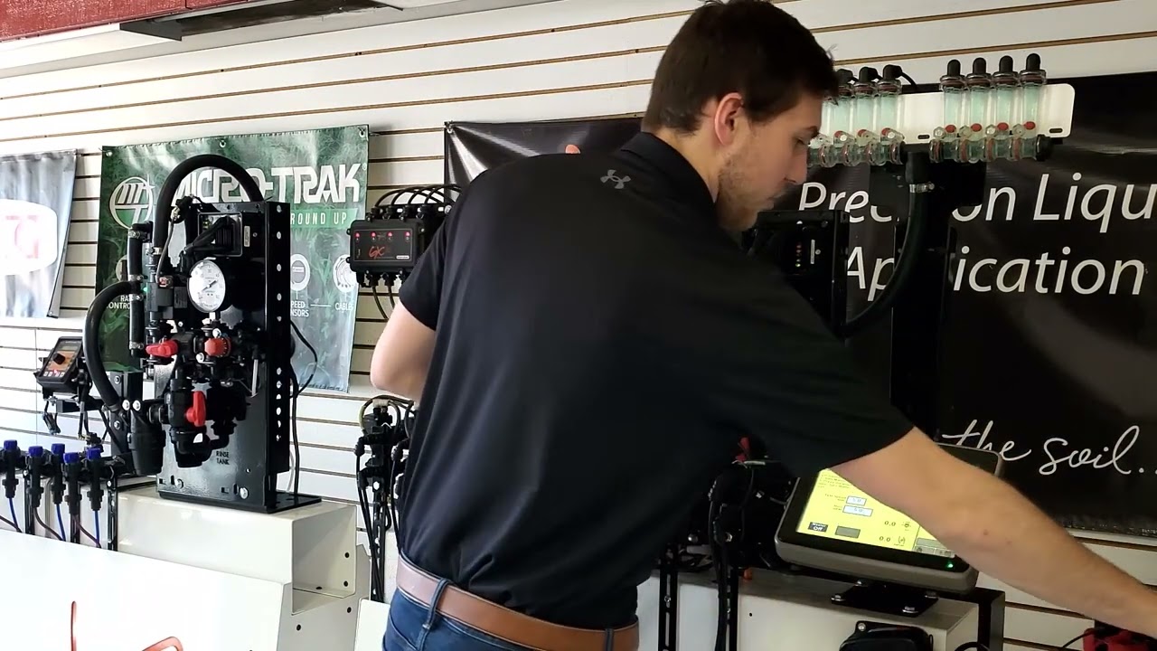
This practical video walks through how to test the voltage and signal output of an industrial flow meter — a foundational step in any diagnostic sequence that rules out electrical causes before investigating the meter itself.
Calibration, Certification, and Compliance
Accurate gas flow measurement is not only an operational requirement — it is a regulatory one for custody transfer, emissions reporting, and utility billing applications.
Key standards governing industrial gas metering:
| Padrão | Organization | Scope |
|---|---|---|
| AGA Report No. 3 | American Gas Association | Orifice metering of natural gas |
| AGA Report No. 7 | American Gas Association | Turbine metering of natural gas |
| AGA Report No. 9 | American Gas Association | Ultrasonic metering of natural gas |
| API MPMS Chapter 5 | American Petroleum Institute | Metering uncertainty for custody transfer (±0.25%) |
| OIML R137 | International Organization of Legal Metrology | Gas meters — metrological and technical requirements |
| ISO 17089 | International Organization for Standardization | Measurement of fluid flow in closed conduits — ultrasonic meters |
| EN 1359 | European Committee for Standardization | Diaphragm gas meters |
For projects serving both US and international clients, confirm which standard governs each measurement point. Mixing AGA and OIML reference conditions without explicit documentation is a common source of cross-border custody transfer disputes.
Calibration traceability means your calibration certificate references a measurement standard that is traceable — through an unbroken chain of comparisons with documented uncertainty — to a national or international standard. NIST (National Institute of Standards and Technology) is the US national metrology body; equivalent bodies include PTB (Germany), NPL (UK), and NIM (China). An A2LA-accredited laboratory (American Association for Laboratory Accreditation) provides the highest level of recognized calibration traceability for gas flow meters in North America.
Preventive Maintenance — Converting Reactive Troubleshooting into Proactive Performance Management
The economics of preventive maintenance are not subtle.
A thermal mass flow meter developing contamination-related sensor drift costs approximately $200–$400 to clean and verify during a planned maintenance window. Left until the drift becomes operationally visible, the remediation cost includes: unplanned process interruption ($1,500–$5,000 depending on the facility), expedited meter removal and inspection ($400–$800), rush recalibration ($600–$1,200), and — if the drift caused billing discrepancy — retrospective financial reconciliation.
Recommended preventive maintenance intervals:
| Tipo de medidor | Functional Check | Cleaning / Inspection | Full Calibration Verification |
|---|---|---|---|
| Thermal mass flow | Every 3 months | Every 6 months | Annually |
| Turbine gas meter | Every 3–6 months | Every 6 months (contaminated gas) | Annually (custody), 2 years (utility) |
| Ultrasonic (inline) | Every 6 months | Annually or as needed | Annually |
| Medidor de vazão Vortex | Every 6 months | Annually | Annually |
| Coriolis | Every 6 months | As needed (typically low) | Annually |
| Diaphragm | Every 12 months | Annually | Per regulatory schedule |
These intervals apply to standard clean-gas service. High-contamination applications — biogas, wet natural gas, compressor discharge — warrant intervals compressed by 50%.
Schedule maintenance around your operations, not your calendar. Align meter inspections with planned shutdown windows. A thermal mass flow meter that should be inspected in August but has a planned plant outage in September is better inspected in September during the shutdown — not forced into an unplanned service call in August because the calendar said so.
Glossary of Key Terms
| Term | Definition |
|---|---|
| ACFM | Actual Cubic Feet per Minute — gas volume at actual operating temperature and pressure, not corrected to a reference condition |
| AGA | American Gas Association — industry organization that publishes widely adopted natural gas measurement standards |
| Calibration drift | The gradual deviation of a meter’s output from its true value over time, caused by wear, contamination, or environmental factors |
| Coriolis meter | A flow meter that measures mass flow directly by detecting the inertial effects of gas flowing through vibrating tubes |
| EMI | Electromagnetic Interference — electrical noise from motors, drives, or nearby power equipment that can corrupt flow meter signal outputs |
| Flow computer | An electronic device that calculates corrected or totalized flow from raw meter signals combined with pressure and temperature inputs |
| HART | Highway Addressable Remote Transducer — a communication protocol that overlays digital data on a standard 4–20 mA signal |
| Fator K | The calibration constant of a flow meter, expressed as pulses per unit volume, used to convert raw output to engineering units |
| Lock-Out/Tag-Out (LOTO) | Safety procedure requiring energy sources to be isolated and labeled before maintenance work begins |
| Nm³/h | Normal cubic meters per hour — gas volume corrected to standard conditions of 0°C and 1 atmosphere |
| OIML | International Organization of Legal Metrology — develops standards for measuring instruments used in regulated applications |
| Pulsation | Rapid, rhythmic pressure fluctuations in a gas line, typically caused by reciprocating compressors or rapid valve cycling |
| RTD | Resistance Temperature Detector — a temperature sensor whose electrical resistance changes predictably with temperature, used for flow compensation |
| SAT | Site Acceptance Test — a formal commissioning verification performed at the installation site before project handover |
| SCADA | Supervisory Control and Data Acquisition — a software platform that monitors, logs, and controls industrial process instruments |
| SCFM | Standard Cubic Feet per Minute — gas volume corrected to 60°F and 14.7 psia reference conditions |
| Thermal mass flow meter | A meter that measures gas mass flow by quantifying heat transfer between a heated sensing element and the flowing gas |
| Relação de redução | The ratio of maximum to minimum measurable flow rate within the meter’s specified accuracy — a wider ratio means more measurement range |
| Medidor de vazão Vortex | A meter that measures flow by counting the frequency of vortices shed from a bluff body obstruction in the gas stream |
The Jade Ant Instruments Technical Foundation
Instrumentos Jade Ant supplies gas flow meters — thermal mass, ultrasonic, turbine, vortex, and Coriolis — to OEM skid manufacturers, EPC contractors, instrument distributors, MRO teams, and municipal utilities across industrial markets worldwide.
Beyond the product catalog, the team provides application engineering support for meter selection, sizing, and installation review during the design phase — the highest-leverage point for preventing the field problems this guide documents. The gas flow meter troubleshooting resources at Jade Ant Instruments e o mass flow meter brands comparison guide are practical starting points for distributors and integrators building their technical competency in gas measurement.
Perguntas frequentes
1. How do I know if my gas meter is reading high or low?
The most reliable method is a side-by-side comparison with a calibrated reference meter. A portable clamp-on ultrasonic meter placed on the same pipe section provides a reference measurement without any process interruption. If a 2–3% difference or greater exists between the reference and the installed meter during stable, mid-range flow conditions, your installed meter has drifted out of specification. For custody transfer applications, a mobile proving unit provides a higher-accuracy reference.
2. What are the most common causes of gas meter inaccuracy in industrial facilities?
Field experience consistently identifies four primary causes: (1) improper installation — insufficient straight-run piping, incorrect orientation, or vibration-prone mounting; (2) wet gas or liquid carryover contaminating sensors; (3) calibration drift from bearing wear, sensor aging, or contamination; and (4) signal interference from ground loops, EMI, or poor cable shielding. Research from gas measurement field studies shows that errors exceeding 20% are documented in real installations from environmental and installation factors — not equipment failure.
3. Can temperature fluctuations affect gas flow readings?
Yes — significantly. Gas is compressible, so its volume changes with temperature. A meter measuring actual volumetric flow without temperature compensation will report higher volumes in warm conditions (gas is less dense) and lower volumes in cold conditions. For a gas line operating between 5°C and 35°C without temperature compensation, the measurement variation is approximately 10% — entirely attributable to temperature, with no change in actual mass throughput.
4. How often should gas meters be calibrated in industrial applications?
The answer depends on application criticality and operating environment. Custody transfer fiscal meters require calibration every 6–12 months per AGA and API MPMS requirements. Process control meters operating in clean, stable conditions can typically be calibrated every 1–2 years. High-contamination applications (biogas, wet gas, compressor discharge) should be calibrated annually regardless of technology. Any meter showing unexplained reading changes should be treated as requiring immediate calibration verification regardless of scheduled interval.
5. What is the minimum straight-run piping required for turbine gas meters?
For a single elbow upstream, turbine meters require a minimum of 10 pipe diameters of straight, unobstructed pipe upstream of the meter inlet and 5 pipe diameters downstream. For a double elbow out-of-plane — the worst-case upstream disturbance — the upstream requirement increases to 20 pipe diameters. These requirements cannot be substituted by recalibration; insufficient straight run produces systematic measurement error that calibration cannot correct.
6. Why is my ultrasonic meter showing zero flow when gas is clearly moving?
Three causes account for the majority of this fault pattern: (1) the actual flow rate is below the meter’s minimum detection threshold — ultrasonic transit-time meters (which measure flow by comparing acoustic pulse travel times upstream and downstream) have a low-flow cutoff below which signal differentiation becomes unreliable; (2) transducer face contamination has attenuated the acoustic signal to the point where the meter cannot establish a valid measurement; or (3) the meter’s signal processing has detected too much noise and defaulted to zero output as a fail-safe. Check the meter’s signal quality or SNR diagnostic parameter first.
7. Can vibration permanently damage a gas flow meter?
Yes. Turbine meters suffer bearing wear and rotor damage from sustained vibration, altering the rotor speed–flow relationship permanently. Vortex meters can experience piezoelectric sensor cracking from high-amplitude mechanical shock. Coriolis meters — while generally robust — can suffer tube fatigue in severe vibration environments with specific resonant frequencies. In all cases, use flexible pipe connections, vibration-absorbing mounting, and assess whether meter relocation away from vibration sources is feasible.
8. How do I verify the 4–20 mA output of my flow transmitter?
Connect a calibrated loop calibrator in series with the 4–20 mA output circuit. With the process at zero flow, the output should be exactly 4.00 mA (representing 0% of range). At full-scale flow, the output should be exactly 20.00 mA (100% of range). At any intermediate flow, the output should be linearly proportional. A discrepancy between the meter’s displayed flow and the corresponding 4–20 mA output indicates an output circuit fault — not a measurement fault — and should be investigated in the meter’s output electronics rather than the sensing element.
9. What should I do if my flow computer displays inconsistent readings?
Start with the inputs, not the flow computer. Verify each input independently: confirm the pressure transmitter reading against a reference gauge at the same tap; confirm the RTD reading against a reference thermometer at the same point; confirm the meter’s primary output (pulse or 4–20 mA) against a direct measurement. If all inputs are verified correct and the flow computer output is still incorrect, check the configuration — reference conditions, gas composition, K-factor, and engineering unit selections. Firmware version and configuration backup verification should follow if configuration appears correct.
10. Is it safe to bypass a gas meter during diagnostic work?
Only under strictly controlled conditions: proper upstream and downstream isolation, full depressurization and purging of the isolated section, a gas-free atmosphere verified by portable gas detector, and active Lock-Out/Tag-Out implemented on all isolation valves. For natural gas systems, additional requirements include hot-work permits for any work involving open flanges, and in many jurisdictions, a gas safety officer or authorized person must be present. Never bypass a gas meter on an active line without completing your full site-specific isolation procedure.
11. How do I detect a gas leak that might be affecting meter performance?
A gas leak upstream of the meter — particularly on the high-pressure side — can cause the meter to report lower flow than is actually entering the pipe section, because some gas is escaping before reaching the meter. Use a calibrated portable gas detector (combustible gas indicator) to survey all flanged connections, valve packings, and instrument impulse lines upstream and around the meter. An ultrasonic leak detector is effective for pressurized leaks that are too small to detect by smell but large enough to affect measurement integrity.
12. Can firmware updates cause measurement problems?
Yes — and this is more common than most teams expect. Firmware updates can reset configuration parameters, change the K-factor entry in the meter’s register, modify the low-flow cutoff threshold, alter the engineering unit conversion, or change the HART command set. Best practice is to export a full configuration backup before any firmware update, and to verify all critical parameters — K-factor, gas type, reference conditions, engineering units, output scaling — immediately after the update is applied. Some manufacturers require that meters be returned to the factory for firmware updates in custody transfer applications to maintain certification validity.
13. What documentation should I maintain for gas meter regulatory audits?
A complete and audit-ready gas meter documentation package includes: installation records (as-built drawings, piping configuration, installation date); calibration certificates for every calibration event with as-found and as-left data; maintenance logs for every inspection, cleaning, and repair; configuration backups with date and firmware version; and any deviation reports documenting instances where the meter operated outside its specified parameters. For custody transfer meters, this documentation must be readily accessible for inspection and retained for the period specified by the applicable regulatory authority — typically 3–7 years depending on jurisdiction.
14. How should I handle a dispute with a customer over gas consumption measurements?
Present your calibration history with traceable certificates showing the meter was within specification during the disputed period. Commission an independent third-party reference measurement by an accredited calibration laboratory — a clamp-on ultrasonic reference meter or mobile proving unit comparison conducted in the presence of both parties provides defensible, independent evidence. If the independent measurement confirms the installed meter’s accuracy, present the results formally in writing. If it identifies a discrepancy, pursue root cause analysis before agreeing to any billing adjustment, as the source of the error determines which party bears responsibility.
15. Are smart gas meters self-diagnosing? Can I trust their alerts?
Modern smart gas meters provide valuable diagnostic data — signal quality indices, sensor health flags, flow stability indicators, and communication error codes — that significantly improve early fault detection compared to conventional meters. However, they are not autonomous diagnostic systems. A “low signal quality” alert requires human interpretation to determine whether the cause is transducer fouling, liquid carryover, or external EMI. A “zero flow” alarm requires verification that actual flow has ceased, not just that the meter has lost measurement. Smart meter diagnostics narrow the field of investigation quickly — but field validation by a technician remains essential. Think of the alerts as your starting point, not your conclusion.
External references used in this guide:
- Sage Metering — True Cost of Inaccurate Gas Flow Measurement
- Power Engineering — Metering Matters: Inaccurate Gas Measurement Can Cost Thousands
- Industrial Monitor Direct — Flow Meter Straight Run Requirements
- Sierra Instruments — Most Common Flow Meter Problems and Solutions
- Kobold USA — Significance of Calibration in Flow Meters
- Flowell — How Often Should Industrial Flow Meters Be Serviced
- Process Vision — Liquid Carryover in Natural Gas Processing
- Jade Ant Instruments — Gas Flow Meter Troubleshooting Guide for Distributors
- Jade Ant Instruments — Custody Transfer Flow Meters: Compliance & ROI Guide
- Jade Ant Instruments — Flow Meter Selection Guide