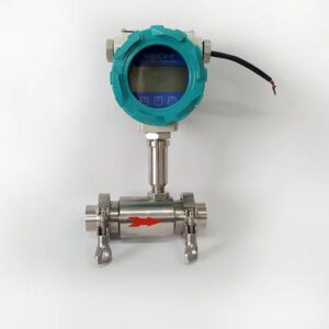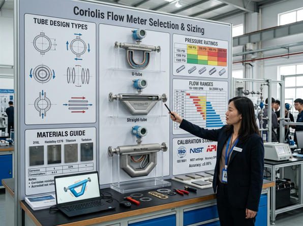
A correctly specified Coriolis flow meter delivers ±0.05–0.2 % mass-flow accuracy — but only when tube design, pressure rating, flow range, and material are each matched to the application. (Image: Jade Ant Instruments)
について Coriolis flow meter is the most accurate direct mass-flow measurement technology available to process engineers today. Unlike differential-pressure meters または electromagnetic meters — both of which infer mass flow indirectly — a Coriolis sensor measures the inertia of the fluid itself as it passes through a vibrating tube, producing a true mass-flow reading with no density, pressure, or temperature correction required under most operating conditions.
Yet that accuracy premium — typically ±0.05 % to ±0.2 % of rate for a correctly sized liquid meter — does not happen automatically. It depends on selecting the right tube geometry, matching tube material to fluid chemistry, sizing the flow range so the meter operates in its linear zone, confirming the sensor body can handle the maximum surge pressure, and installing the device where external vibration cannot corrupt the phase-shift signal.
Get even one of those decisions wrong and you can easily forfeit the accuracy advantage entirely. A dual-bent-tube meter installed at 8 % of its rated full-scale flow — chosen simply because its flange matched the pipe bore — produces errors twelve times worse than its datasheet specification. In a custody-transfer natural-gas application running at USD 3 per MMBTU, that error can translate to a USD 28,000 monthly billing discrepancy.
This guide, developed with field expertise from ジェイド・アント・インストゥルメンツ, walks through every sizing and selection decision — from tube geometry and wetted material choice through Maximum Allowable Pressure, calibration traceability, and a practical 8-step procurement workflow — so your next Coriolis specification is right the first time.
How a Coriolis Flow Meter Works — The Physics Behind the Phase Shift
Understanding the measurement principle is the prerequisite for making every sizing decision that follows. A Coriolis meter contains one or two flow tubes that an electromagnetic drive actuator excites at their natural resonant frequency. When no fluid is flowing, both the inlet and outlet sections of the tube vibrate in perfect synchrony — zero phase difference between them.
When fluid flows through the vibrating tube, the Coriolis force causes the tube to twist: the inlet arm lags behind the overall vibration and the outlet arm leads ahead. The phase shift between the two vibration sensors is directly and linearly proportional to the mass flow rate, regardless of fluid density, viscosity, temperature, or pressure (within the calibrated operating range). The transmitter converts this phase shift into a 4–20 mA or digital output in real time.
Simultaneously, the resonant frequency of the tubes changes as fluid density changes — because adding denser fluid inside the tube is analogous to adding mass to a vibrating string, which lowers its pitch. The transmitter uses this frequency shift to calculate fluid density directly, without any external input.
▶ The Coriolis Flow Measuring Principle — Endress+Hauser animation. Shows tube vibration, Coriolis-force phase shift, and how the transmitter converts phase difference to mass flow. (YouTube, ~3 min)
Three measurement variables are available from a single sensor: mass flow rate, fluid density, and — through calculation — volume flow rate. No external pressure transmitter, temperature transmitter, or density cell is required for mass flow accuracy. This multi-variable capability is one of the technology’s most powerful commercial advantages, reducing instrument count, wiring, and maintenance touchpoints on dense piping systems.
Tube Configurations: Dual-Tube vs. Single-Tube, Bent vs. Straight
The Endress+Hauser Proline Promass K 10: a compact dual-tube Coriolis meter for utility and general-purpose process measurement, rated to PN 40 / Class 300 with 316L stainless steel or 904L measuring tubes. (Image: Endress+Hauser product catalogue)
Dual-Tube Designs and Their Vibration Immunity Advantage
Dual-tube meters split the fluid stream into two parallel flow tubes that vibrate in counter-phase — as one tube moves up, the other moves down. This counter-vibration arrangement provides inherent immunity to external mechanical vibration, because any common-mode disturbance (e.g. from a nearby pump or compressor) acts identically on both tubes and cancels out in the phase-difference calculation. Dual-tube designs dominate applications where external vibration is present, where custody-transfer accuracy is required, or where the process environment is generally demanding.
The leading dual-tube products in 2025 — the Emerson Micro Motion ELITE, Endress+Hauser Promass F/X 300, and Yokogawa RotaMASS TI — achieve liquid mass-flow accuracy of ±0.05–0.10 % of rate and density accuracy of ±0.0005 g/cm³. The trade-off is pressure drop: because the flow splits through two narrower tubes, the hydraulic resistance is higher than for a single-tube design of the same nominal line size.
Single-Tube Designs: Hygienic Applications and Low Pressure Drop
Single-tube meters pass the entire flow stream through one tube, eliminating the internal divider and all dead-space between parallel tubes. This makes them the natural choice for hygienic and pharmaceutical applications where CIP (Clean-in-Place) compliance and full self-draining are mandatory. They also offer lower pressure drop than equivalent dual-tube models and handle highly viscous fluids — adhesives, polymer melts, chocolate — with less risk of tube clogging or build-up in dead zones.
The Endress+Hauser Promass H series (Hastelloy or Tantalum single tube) and Promass I series (Titanium single tube for low-pressure-loss service) are representative product lines. The single-tube arrangement is more sensitive to external vibration than dual-tube designs, requiring careful mechanical isolation from pumps and compressors.
Bent-Tube (U-Tube, Ω-Tube) vs. Straight-Tube Geometry
Within both dual- and single-tube families, the tube can be shaped as a bent curve (U, Ω, or figure-eight) or kept straight. Bent-tube designs use the curved geometry to create a longer moment arm for the Coriolis force, which amplifies the phase-shift signal at low mass-flow rates — giving better sensitivity and turndown. They are preferred for high-accuracy liquid measurement where installation space is not severely constrained. Straight-tube designs are more compact, fully self-draining, and tolerate entrained gas (GVF) better than bent tubes — making them the better choice for crude oil allocation metering, where small gas slugs are expected, and for applications with very limited headroom above or below the pipeline.
| 設定 | Best Suited Application | 精度 | 圧力降下 | Drainability | Vibration Immunity |
|---|---|---|---|---|---|
| Dual-tube bent (U/Ω) | Custody transfer, high-accuracy liquid, chemical plants | ±0.05–0.10 % of rate | Medium–High | Partial — dead legs possible | Excellent (counter-phase cancellation) |
| Dual-tube straight | Crude oil allocation, compact skid packages, moderate GVF | ±0.10–0.15 % of rate | 低~中 | Good — fully self-draining if oriented correctly | いいね |
| Single-tube straight | Pharma CIP, food & beverage, high-viscosity fluids | ±0.10–0.15 % of rate | 低 | Excellent — zero dead volume | Moderate — requires isolation from vibration |
| Four-tube (e.g. Promass X) | Very high flow rates (>1,000 t/h), offshore oil & gas | ±0.05–0.10 % of rate | Low (large bore) | いいね | 素晴らしい |
Tube Material Selection: Corrosion, Temperature, and Fatigue
The Endress+Hauser Proline Promass X 300: a four-tube design rated to PN 100 / Class 600, handling up to 2.2 million kg/h — engineered for offshore oil and gas custody transfer where single-meter redundancy is critical. (Image: Endress+Hauser product catalogue)
Why Material Selection is Critical for Coriolis Tubes
Coriolis tube material selection must simultaneously satisfy two demands that can pull in opposite directions: chemical compatibility with the process fluid and cyclic fatigue endurance. Every Coriolis tube flexes hundreds of times per second throughout its entire service life. Any surface defect introduced by corrosion — even shallow pitting — accelerates fatigue crack propagation dramatically, because cracks grow from stress concentrations. A tube that appears superficially sound under visual inspection can fail catastrophically from fatigue-driven crack propagation that started at a micro-pit.
This is why specifying “316L stainless steel for everything unless there’s an obvious corrosion concern” is an engineering risk, not a conservative choice. For chloride-containing processes, HCl service, or seawater injection, 316L can fail by stress corrosion cracking (SCC) within 12–24 months, long before the next scheduled inspection.
| 素材 | Key Chemical Resistance | Max. Temp. | 主な制限事項 | Typical Application |
|---|---|---|---|---|
| 316L Stainless Steel (1.4404/1.4435) |
Water, hydrocarbons, dilute acids, most solvents | ~350 °C | Chloride SCC above ~60 ppm Cl⁻ at elevated temperature | General-purpose liquid/gas, food & beverage, clean utilities |
| Hastelloy C-22 (Alloy C22, 2.4602) |
HCl, H₂SO₄, chlorinated solvents, seawater, wet chlorine | ~350 °C | Higher cost; limited availability in larger bore sizes | Chemical industry, acid services, offshore seawater injection |
| ハステロイ C-276 | Strong oxidising and reducing acids, chlorides, H₂S | ~370 °C | Similar to C-22; more widely stocked in North America | Sour gas, mixed acid, chloride-rich brine |
| Inconel 625 (Alloy 625) |
High-temperature hydrocarbon, sour gas, cryogenic LNG | ~650 °C | Expensive; requires specialist welding qualification | Subsea, cryogenic LNG, high-temp process |
| Titanium Grade 9 | Seawater, oxidising acids, chlorine solutions | ~315 °C | Not suitable for HF; low thermal conductivity may affect density accuracy | Low-pressure-loss service (Promass I series), marine |
| Tantalum 2.5W | Fuming H₂SO₄, HCl at all concentrations, HNO₃, HF | ~300 °C | Brittle at cryogenic temperatures; very high material cost; niche only | Highly corrosive specialty chemicals, Promass H Tantalum |
| Super Duplex 25Cr (UNS S32750) |
High-chloride seawater, sour crude, offshore produced water | ~280 °C | Susceptible to sigma-phase embrittlement above 280 °C | Offshore high-pressure custody transfer (Promass O series) |
For a comprehensive compatibility matrix across 400+ process chemicals, refer to the Emerson Micro Motion Corrosion Guide.
Flow Range Sizing, Turndown, and the Operating-Point Accuracy Rule
The Endress+Hauser Proline Promass U 500: the industry’s first single-use Coriolis meter — meeting cGMP requirements for biotech and pharmaceutical single-use processes, with a disposable sensor and re-usable transmitter. (Image: Endress+Hauser product catalogue)
Why the Operating Point Determines Real-World Accuracy
Accuracy specifications on Coriolis meter datasheets are almost always expressed as % of full-scale (FS) または % of rate (reading). These are not the same thing — and confusing them is the single most common source of specification errors in the field.
A meter specified at ±0.1 % FS with a 1,000 kg/h full-scale range has an absolute error allowance of ±1 kg/h at all flow rates. At 1,000 kg/h (100 % FS), this equals ±0.1 % of reading. But at 100 kg/h (10 % FS), the same ±1 kg/h absolute error equals ±1.0 % of reading. At 50 kg/h (5 % FS), it becomes ±2.0 % of reading. The meter’s headline accuracy deteriorates rapidly at low flow when specified as % FS.
% of rate specifications (also called “% of reading”) are more demanding and more meaningful: a ±0.1 % of rate specification maintains the same relative accuracy at all flow levels within the rated turndown range. Always specify accuracy as % of rate for custody-transfer, fiscal, or mass-balance applications.
Practical Flow Range Sizing: The Three-Flow-Figure Method
Before opening a vendor catalogue, define three flow figures from your process design basis: minimum flow (including startup and low-production periods), normal operating flowそして maximum emergency flow. Then apply these sizing rules:
- Normal operating flow should fall at 40–70 % of the meter’s full-scale range — well within the high-accuracy zone.
- Minimum flow must remain above 10 % of full-scale to stay within the rated turndown ratio and accuracy envelope.
- Maximum emergency flow should not exceed 90 % of full-scale, preserving headroom for future capacity increases and avoiding the pressure-drop penalty at very high velocities.
If meeting all three criteria requires accepting a higher pressure drop (by using a smaller sensor body than the pipe bore), that trade-off is usually worthwhile. Pressure drop through a correctly sized Coriolis meter should ideally not exceed 0.5 bar (7.3 psi) at normal flow for liquid service, but this is a guideline — run the manufacturer’s sizing tool to confirm the exact figure for your conditions.
Turndown Ratio — What It Really Means in Practice
ターンダウン比 for Coriolis meters typically ranges from 20:1 to 100:1 depending on the tube configuration and transmitter model — significantly better than differential-pressure meters (3:1 to 10:1) or turbine meters (10:1 to 20:1). However, the published turndown figure is only valid at the published accuracy level. Alicat Scientific’s M-series instruments achieve 10,000:1 turndown in laboratory gas service, but this is only possible because the instrument is designed and calibrated specifically for that extreme range; industrial process meters do not achieve this.
| # | パラメータ | Why It Matters | Typical Range |
|---|---|---|---|
| 1 | Fluid mass flow: min / normal / max | Determines sensor body size and operating-point accuracy | 0.001 g/h → 2,200,000 kg/h |
| 2 | Maximum surge pressure (bar g) | Must not exceed sensor MAP; surge spikes can deform tubes permanently | Vacuum → 700 bar |
| 3 | Fluid temperature: min / max | Drives tube material, seal material, and transmitter housing class | –196 °C → +426 °C |
| 4 | Fluid phase (liquid / gas / multiphase) | Entrained gas above 2 % GVF degrades accuracy; special firmware or upstream separation may be needed | Single-phase preferred |
| 5 | Required accuracy (% of rate) | % of rate is the only meaningful specification for custody transfer or mass balance; never accept % FS alone for critical applications | ±0.05 % → ±1.0 % of rate |
Pressure Ratings, MAP, Surge Pressure, and Pressure Drop
Understanding Maximum Allowable Pressure (MAP)
Maximum Allowable Pressure (MAP) is the most safety-critical figure on the Coriolis meter datasheet. Exceeding MAP — even briefly during a water-hammer event — can permanently deform the flow tubes. A deformed tube shifts the meter’s zero reading and degrades accuracy; in extreme cases, tube rupture creates a loss-of-containment hazard.
Modern Coriolis sensors span a wide pressure range: compact laboratory models may be rated to 6 bar (87 psi) — such as the Endress+Hauser Promass U 500 single-use series — while high-pressure models for subsea and hydraulic test stands reach 350–700 bar (5,000–10,000 psi). The Endress+Hauser Promass O series (Super Duplex tubes) is rated to PN 250 / Class 1500, covering typical offshore high-pressure crude oil applications.
Pressure Drop Sizing Principles
Pressure drop through a Coriolis meter scales approximately with the square of the volumetric flow rate through the sensor tube. A correctly sized meter imposes a pressure drop in the range of 0.1–0.5 bar at normal flow — acceptable for most process systems. An undersized meter (e.g. a DN15 sensor body on a DN50 line, chosen to improve low-flow accuracy) may impose several bar of pressure drop at maximum flow, eroding pump head and increasing energy cost.
Use the manufacturer’s online sizing tool — Emerson’s Flow Measurement Sizing and Selection Tool is freely accessible — to calculate predicted pressure drop at both normal and maximum flow before finalising sensor body size.
External Vibration: The Hidden Threat to Coriolis Accuracy
External mechanical vibration can excite the Coriolis tube at frequencies close to its natural resonant frequency, causing the transmitter to misinterpret mechanical noise as genuine mass-flow phase shift. This produces a “zero-flow offset” — the meter reads a non-zero flow when the line is actually static — and a corresponding flow-measurement error during operation.
Practical mitigation endorsed by the TÜV SÜD / NEL Coriolis Good Practice Guide includes: installing the meter body on its own rigid support bracket mechanically isolated from the process pipe using stainless corrugated flex hoses or PTFE expansion joints; specifying a dual-tube design (counter-phase vibration rejects common-mode disturbances); and choosing a transmitter with digital notch-filter DSP tuned to reject the known excitation frequencies of nearby rotating equipment.
Installation Orientation and Straight-Run Requirements
Unlike every other flow meter technology, Coriolis meters require zero straight pipe runs upstream or downstream. The measurement principle depends entirely on the inertia of fluid inside the vibrating tube — not on the upstream velocity profile — so a Coriolis sensor can be installed immediately downstream of elbows, control valves, or pump outlets without any measurement error from flow profile distortion. This is one of the technology’s most valuable installation advantages on congested offshore platforms and skid-mounted process units.
For liquid service, install the meter so the tubes point downward in a horizontal run, or in a vertical run with upward flow — both orientations ensure tubes remain full and gas cannot accumulate. Avoid installations at the top of a pipeline loop where gas pockets can collect in the sensor tubes.
Application Sectors and Market Share
- 石油・ガス — 33 % (custody transfer, allocation metering, LNG)
- 化学処理 — 22 % (acid dosing, solvent blending, reactor feed)
- フード&ビバレッジ — 15 % (filling, batching, CIP-qualified lines)
- Pharmaceuticals — 14 % (API batching, single-use biotech)
- 上下水道 — 9 % (chemical dosing, sludge flow)
- Other (semiconductor, paper, mining) — 7 %
Source: Compiled from Grand View Research flow meter market report (2025) and segment data. Figures are industry estimates; individual research firms may report slightly different breakdowns.
Calibration, Standards, and Certifications
The Endress+Hauser Proline Promass G 100: the industry’s most compact high-pressure Coriolis sensor, rated to 350 bar (5,080 psi) and covering flow ranges from trace quantities up to 18,000 kg/h — suited for high-pressure gas metering and hydraulic test stands. (Image: Endress+Hauser product catalogue)
Factory Calibration, Traceability, and ISO 17025
A Coriolis meter’s factory calibration certificate establishes the certified relationship between the raw phase-shift signal and the mass-flow output. For the certificate to be legally defensible in custody transfer, it must be traceable to a national measurement institute (NMI — NIST, PTB, NPL, etc.) and performed by an ISO/IEC 17025-accredited laboratory.
Not all factory calibration certificates are equivalent. A “factory calibration” performed on an internal rig with no accreditation body and no stated uncertainty value is not equivalent to an accredited certificate. Always require the calibration certificate to state: the accreditation body, the certificate number, the calibration laboratory’s accreditation scope, the calibration fluid and conditions, and the expanded uncertainty at 95 % confidence level. For more background, the ISA article on Coriolis flowmeter calibration provides a thorough technical overview.
Key Standards and Certifications Reference
| Standard / Certification | Scope | Require When |
|---|---|---|
| OIML R 117 | Measuring systems for liquid custody transfer; accuracy classes 0.3, 0.5, 1.0, 1.5 | Petroleum, chemical, or water fiscal metering |
| ISO/IEC 17025 | Laboratory calibration competence; governs the facility issuing the calibration certificate | Any application requiring traceable calibration (fiscal, pharmaceutical, legal-for-trade) |
| ATEX / IECEx | Equipment for explosive atmospheres — Zone 0, 1, 2 (gas); Zone 20, 21, 22 (dust) | Any hazardous area installation |
| PED 2014/68/EU (CE) | Pressure Equipment Directive; governs the pressure-containing parts for EU market | All EU installations; Category I–III based on fluid group and design pressure |
| API MPMS Chapter 5.6 | Measurement of liquid hydrocarbons by Coriolis meter; installation, calibration, and verification procedures | Oil and refined product custody transfer in North America |
| SIL 2 / SIL 3 | Functional safety per IEC 61508 / IEC 61511; relevant when the meter output feeds a safety instrumented function | Safety-critical shutdown or ESD loops using Coriolis measurement |
| NACE MR0175 / ISO 15156 | Material requirements for oil and gas service with H₂S (sour service) | Any application with H₂S > 0.05 psia partial pressure in gas phase |
Calibration Intervals and In-Situ Verification
Calibration intervals should be set by a documented risk-based approach rather than arbitrary time periods. For custody-transfer fiscal metering, most regulatory frameworks require annual verification. For process control and mass balance, 2–5 year intervals are common, supported by regular in-situ zero verification (quarterly is typical). Transmitters with built-in Coriolis Health Monitoring — Emerson’s Smart Meter Verification, E+H’s Heartbeat Technology — track drive gain, tube frequency, and sensor balance continuously, enabling condition-based maintenance: the meter calls for service when diagnostics indicate drift, not when the calendar says so.
8-Step Sizing Workflow and Real-World Case Studies
Step-by-Step Decision Process for a New Installation
Case Study A — Wet Natural Gas, 80 bar, H₂S Present
A gas transmission operator needed well-head tie-in metering for a wet gas stream (3–8 % water vapour, 12 ppmv H₂S, 80 bar). NACE MR0175 compliance was required. The selected solution used a straight-tube dual-meter arrangement in manifolded redundancy with Hastelloy C-276 tubes rated to 140 bar (1.75× operating pressure, covering 95-bar surge events), an Ex d ATEX Zone 1-certified transmitter, and advanced gas-correction firmware. Measured uncertainty at 95 % CL: ±0.3 % of rate — within OIML Class 1.0 specification. Annual billing reconciliation discrepancy across four metering runs: zero disputed invoices in the first three years of service.
Case Study B — High-Viscosity Adhesive, 15,000 mPa·s, 60 °C
A sealant manufacturer needed to account for epoxy resin batches to ±0.5 % by mass. High viscosity eliminated turbine and ultrasonic meters. A 316L SS single-tube Coriolis meter (DN10 sensor body on a DN25 line) was selected, accepting 0.9 bar pressure drop at normal flow to keep the operating point at 55 % of FS. Accuracy validated against a certified weigh scale across ten independent batches: ±0.19 % of rate — well inside specification. Viscosity independence meant no re-calibration was required when switching between two epoxy grades of different viscosity.
Case Study C — Biotech Single-Use Buffer Preparation, cGMP Required
A biopharmaceutical manufacturer building a single-use buffer preparation suite needed a mass flow meter that could be discarded with the single-use bag assembly after each batch — eliminating cross-contamination risk and CIP validation burden entirely. The Endress+Hauser Promass U 500 single-use Coriolis meter was specified: disposable sensor tube, re-usable transmitter, cGMP-compliant materials, and integration with the existing FOUNDATION Fieldbus DCS. Batch-to-batch mass accuracy: ±0.4 % of target, replacing manual weighing that had been achieving only ±1.8 %.
For a wider comparison of Coriolis brands by application, see Top Coriolis Mass Flow Meters for Industrial Applications on Jade Ant Instruments, and the team’s detailed analysis of top Coriolis transmitter selection mistakes.
Procurement Checklist and Vendor Scoring Rubric
Mandatory Documentation to Request Before Issuing a PO
- Factory calibration certificate with ISO/IEC 17025 accreditation details, calibration body name, standard number, and expanded uncertainty at 95 % CL
- Dimensional data sheet (face-to-face length, flange rating and drilling pattern, sensor weight, centre-of-gravity data for structural support design)
- Material traceability certificates: 3.1 material test reports per EN 10204 for all pressure-containing wetted parts
- ATEX / IECEx certificate (if hazardous area) — including notified body name, certificate number, Ex marking breakdown, and applicable Zone classification
- PED Category declaration and CE conformity statement (for EU installations)
- Hydraulic proof-pressure test certificate: minimum 1.5× MAP, with test fluid, duration, and accept criteria stated
- Functional test certificate (4–20 mA loop check, HART or fieldbus communication test against the specified protocol)
- Datasheet showing confirmed operating ranges for your specific fluid, temperature, and pressure — not the generic water/air reference conditions used in the standard catalogue
- NACE MR0175 / ISO 15156 compliance statement (if H₂S concentration requires sour-service qualification)
- SIL certificate with proof-test interval and SFF data (if the meter feeds a safety instrumented function)
Vendor Scoring Rubric (Adapt for Your RFQ)
| Criterion | Weight | Vendor A | Vendor B | Vendor C | Scoring Notes |
|---|---|---|---|---|---|
| Accuracy (% of rate at normal operating point) | 25 % | 5 | 4 | 3 | ±0.05 % = 5 | ±0.10 % = 4 | ±0.20 % = 3 |
| Pressure rating vs. MAP + surge requirement | 15 % | 5 | 5 | 3 | Must exceed max surge + 10 % safety margin |
| Tube material compatibility confirmed (corrosion guide) | 15 % | 5 | 4 | 4 | Verified against corrosion data, not general claims |
| ATEX / IECEx certification (if required) | 10 % | 5 | 5 | 2 | Zone 1 requires II 2 G Ex d IIB/IIC T4 or Ex ia |
| ISO 17025-accredited calibration with traceability | 10 % | 5 | 4 | 3 | Verify accreditation body and scope of accreditation |
| Communication protocol match (HART / Profibus / FF / Modbus) | 8 % | 5 | 3 | 4 | Must integrate with existing DCS / PLC without additional I/O cards |
| Built-in diagnostics (drive gain, zero verification, tube integrity) | 7 % | 5 | 3 | 2 | Advanced diagnostics reduce 10-yr maintenance cost significantly |
| Spare parts availability and regional lead time | 5 % | 4 | 5 | 3 | Critical for remote sites; verify warehouse stock vs. factory order |
| 5-year total lifecycle cost (purchase + install + calibration + repair) | 5 % | 4 | 3 | 5 | Lowest purchase price rarely means lowest lifecycle cost |
| Weighted Total Score | 100 % | 4.87 | 4.05 | 3.13 | Score = Σ(weight × score) ÷ 100 |
結論
A Coriolis flow meter correctly specified and sized is the most powerful single-instrument investment available in industrial flow measurement — delivering direct mass flow, fluid density, and volume flow simultaneously at ±0.05–0.2 % of rate accuracy, with no straight-pipe-run requirements and a diagnostic capability that enables condition-based maintenance rather than calendar-based replacement.
But that performance is entirely contingent on getting five inter-dependent decisions right simultaneously: tube configuration, tube material, flow range operating point, pressure rating relative to surge conditions, and certification compliance. The 8-step sizing workflow, vendor scoring rubric, and procurement documentation checklist in this guide provide a systematic framework for making all five decisions correctly, regardless of application sector or fluid type.
The most durable lesson from field experience: the cheapest Coriolis meter on the purchase order is almost never the cheapest meter over five years. A correctly specified premium meter that runs 20 years without a tube failure, calibration drift, or zero-point shift will consistently outperform a cost-optimised specification that requires field modifications, early replacement, or billing dispute resolution.
Explore Jade Ant Instruments’ full resource library for further reading: Coriolis Flow Meter Pros and Cons: 2026 Full Guide and the comprehensive Mass Flow Meter Brands Comparison covering nine leading manufacturers with verified specifications.
よくある質問
Start by identifying three mass-flow values from your process design basis: minimum (including startup and low-production periods), normal operating, and maximum emergency flow. Then select a meter model whose full-scale range puts normal flow at 40–70 % of FS, keeps minimum flow above 10 % of FS (to remain within the rated turndown and accuracy zone), and keeps maximum flow below 90 % of FS. Run the manufacturer’s sizing tool to confirm the resulting pressure drop is within your system’s available head. Finally, verify tube material compatibility and MAP vs. surge pressure before finalising the order. Sizing to match pipe bore rather than flow range is the most common and most consequential mistake in Coriolis meter specification.
% of full-scale (FS) is an absolute error allowance that remains constant in engineering units regardless of the actual flow rate. At low flow, this fixed absolute error becomes a large fraction of the reading — a ±0.1 % FS meter at 10 % of its range is effectively delivering only ±1.0 % of rate accuracy. % of rate (also called % of reading) maintains the same relative accuracy at all flow levels within the rated turndown — ±0.1 % of rate means the error is always 0.1 % of whatever the meter is actually reading. For custody transfer, fiscal metering, or mass balance applications, always specify and compare meters on a % of rate basis. A meter advertised with a lower % FS figure but without a stated % of rate specification may actually be worse at your normal operating point than a competitor with a higher % FS but a stated % of rate specification.
The correct answer depends on the specific chemical, its concentration, temperature, and whether there is any risk of stress corrosion cracking given the cyclic vibration inherent to all Coriolis tubes. As a starting framework: for hydrochloric acid at any concentration, dilute sulphuric acid, chlorinated solvents, or seawater — specify Hastelloy C-22 or C-276. For hydrofluoric acid or reducing acid services — consider Monel 400 or Tantalum (at concentrations and temperatures where Hastelloy is not sufficient). For fuming sulphuric acid or the most aggressive mineral acids — Tantalum is the last-resort option. For standard hydrocarbon, clean water, and food-grade service — 316L stainless steel is appropriate. Never rely on generic material compatibility charts that do not account for cyclic fatigue conditions; always cross-reference against the vendor’s own corrosion guide data.
No. Coriolis meters require zero straight pipe runs upstream or downstream. The measurement principle is based on the inertia of fluid inside the vibrating tube — not on the velocity profile at the meter inlet — so the sensor is completely insensitive to upstream flow disturbances from elbows, valves, reducers, or tees. This is one of the Coriolis meter’s most valuable installation advantages on congested piping systems or offshore platforms where straight-run space is at a premium. The important caveat is that the meter body must still be supported independently of the process pipe to prevent bending moments from pipe thermal growth from shifting the zero reading.
For ATEX Zone 1 (gas, vapour, or mist explosive atmosphere present occasionally in normal operation), the meter must carry a minimum of ATEX II 2 G marking — indicating Equipment Group II (surface industry), Category 2 (suitable for Zone 1), Gas/Vapour. The protection concept is typically Ex d (flameproof enclosure) for the sensor housing, or Ex ia (intrinsic safety) for a loop-powered version. The specific gas group (IIA, IIB, or IIC — depending on whether the hazardous gas is propane, ethylene, or hydrogen) and temperature class (T1–T6, based on maximum surface temperature) must also match the hazardous area classification. The ATEX certificate must carry a reference number from an EU Notified Body. For installations outside the EU, the equivalent IECEx certificate is the internationally recognised equivalent, issued by an ExCB (Certification Body).
Yes. Coriolis meters measure both gases and liquids by the same fundamental principle. However, gas measurement is inherently more challenging because gas has much lower mass density than liquid — the Coriolis force acting on the gas mass is smaller, requiring the transmitter to detect a smaller phase shift and making the measurement more sensitive to background noise. A correctly specified Coriolis meter in gas service typically achieves ±0.5–1.0 % of rate, compared to ±0.05–0.2 % of rate for liquid service. For compressed natural gas (CNG), nitrogen, or high-pressure industrial gases, select a model specifically validated for gas measurement at your operating pressure and temperature. Some models require the meter to be derated — operating the full-scale range at a lower value — when measuring gas rather than liquid, because the lower mass flow in volumetric terms means slower phase shift development. Always confirm gas accuracy figures explicitly with the manufacturer at your actual operating conditions.
Maximum Allowable Pressure (MAP) is the highest internal pressure the Coriolis meter’s pressure-containing components (flow tubes, manifolds, and housing) can safely sustain without permanent deformation — it is stamped on the sensor nameplate. Normal operating pressure is the typical process line pressure during steady-state production. MAP must exceed not just normal operating pressure, but the maximum surge or transient pressure the system can generate. In pump-driven liquid systems, valve-slam events and pump trip scenarios can produce pressure spikes 2–3 times the normal operating pressure in under 100 milliseconds. If MAP is set equal to 1.2× normal operating pressure without accounting for a possible 200-bar surge, and the actual surge reaches 180 bar on a sensor with a 160-bar MAP, the tubes deform and the meter requires replacement. The design rule is: MAP must exceed 1.1 × maximum credible surge pressure, calculated from a hydraulic transient analysis of the piping system.
Entrained gas (bubbles in a primarily liquid flow stream) is the most significant operational challenge for Coriolis meters. At gas void fractions below approximately 2 %, most dual-tube meters continue to measure with errors typically below 0.5 % of rate. As GVF increases above 5 %, tube damping rises sharply, drive gain increases, and measurement errors grow non-linearly — some transmitters report a diagnostic alarm but continue measuring; others lose signal lock completely. The recommended approach in order of preference: first, use upstream process design to minimise GVF before the meter (inline separator, coalescing filter, or deaeration vessel); second, if upstream separation is not practical, select a transmitter with a validated two-phase correction algorithm and clearly understand the published error bounds at your expected GVF range; third, for crude oil allocation where well-stream GVF is unpredictable, install the Coriolis meter downstream of a test separator rather than attempting direct multiphase measurement.
Calibration frequency should be set by a risk-based approach that accounts for the consequence of measurement error and the historical drift rate of the specific meter model in your service. For custody-transfer fiscal metering (oil, gas, LNG), most regulatory and contractual frameworks mandate annual verification using an accredited calibration rig. For process control and mass balance applications where errors have lower direct financial consequence, 2–5 year intervals are common when supported by quarterly in-situ zero verification checks. Transmitters with built-in Coriolis health monitoring — such as Emerson’s Smart Meter Verification or Endress+Hauser’s Heartbeat Technology — continuously track diagnostic parameters (drive gain, tube resonance frequency, sensor balance) and can flag drift before it affects the measurement significantly, enabling condition-based calibration scheduling rather than fixed calendar intervals.
Based on post-installation reviews across dozens of industrial projects, the most frequently recurring mistakes are: (1) sizing the meter to match the pipe bore rather than the flow range — producing low-flow operation at poor accuracy; (2) specifying MAP equal to normal operating pressure without accounting for surge transients; (3) defaulting to 316L stainless steel for all services without verifying chloride concentration and temperature for SCC risk; (4) mounting the sensor body directly on an unsupported branch line, allowing pipe thermal expansion to impose bending moments that shift zero and fatigue manifold welds; (5) requesting a calibration certificate without specifying ISO/IEC 17025 accreditation, resulting in non-traceable certificates that do not satisfy custody-transfer requirements; and (6) disabling temperature compensation in the transmitter during commissioning, introducing a density error that grows with process temperature deviation from the calibration reference condition. Each of these can be fully avoided by following the 8-step sizing workflow and using the procurement documentation checklist provided in this guide.