The Critical Role of Flow Measurement in Water Treatment Efficiency
Flow measurement is one of the most important functions in any water treatment plant. Without accurate flow data, operators cannot control chemical dosing, verify filtration performance, track discharge compliance, or manage energy costs with any confidence. Get it wrong, and the consequences range from failed regulatory audits to equipment damage and unsafe water quality.
For EPCs (Engineering, Procurement, and Construction contractors), system integrators, and OEM skid builders, the instrumentation decisions made during project design have effects that last for the full lifecycle of the plant — often 15 to 25 years. Yet flow meter selection frequently gets treated as a late-stage procurement decision rather than a design-stage engineering choice.
This guide addresses the three problems that EPC teams consistently encounter when specifying flow instrumentation:
Inconsistent data quality — when flow meters are oversized, undersized, or incorrectly installed, the readings drift or oscillate, making process control unreliable and triggering false alarms in SCADA systems.
High total cost of ownership — smart and digital meters carry a premium at purchase, a higher integration cost at commissioning, and more complex maintenance requirements over their operating life. For non-critical monitoring points, this premium rarely delivers proportionate value.
Integration complexity — adding digital fieldbus protocols to every measurement point in a plant adds configuration overhead, requires specialised commissioning expertise, and increases the risk of communication faults during startup.
Analog flow meters — devices that output a continuous 4–20 mA signal (a standard electrical current range where 4 mA represents zero flow and 20 mA represents maximum flow) — address all three of these problems for a broad range of water treatment applications. They are not a legacy compromise. They are a deliberate engineering choice.
Why Analog Flow Meters Still Matter in Modern Water Treatment Systems
Analog Does Not Mean Outdated
The word “analog” tends to trigger assumptions about obsolescence — an understandable reaction in an industry where digital fieldbus devices, IIoT sensors, and cloud-connected transmitters receive most of the marketing attention. But the assumption is technically wrong, and commercially costly for any project team that acts on it.
Analog flow meters — particularly magnetic flow meters (magmeters) and variable area meters (rotameters with transmitter outputs) — remain the dominant technology in water treatment infrastructure globally. The reason is straightforward: they are reliable, predictable, and fully compatible with modern control systems through their 4–20 mA output.
について Emergent Water SCADA integration guide notes that traditional 4–20 mA analog signals remain the most widely deployed signal standard in municipal water infrastructure — and for good reason. A 4–20 mA loop needs only two wires, is inherently noise-resistant across cable runs of several hundred meters, and connects directly to any PLC analog input card or RTU input module without protocol configuration or firmware.
When Analog Is the Smarter Engineering Choice
The honest comparison is not “analog vs. digital” — it is “what does this measurement point actually need?” The table below summarises when each technology earns its place:
| Measurement Scenario | Analog Meter | Smart/Digital Meter |
|---|---|---|
| Non-critical process line monitoring | ✅ Ideal — low cost, simple wiring | ⚠️ Overengineered — higher cost, unnecessary |
| Regulatory billing or custody transfer | ⚠️ Check accuracy grade required | ✅ Preferred for audit-grade data |
| Harsh environments (sludge, abrasives) | ✅ Magmeters — no moving parts | Variable — depends on meter type |
| Budget-constrained EPC or OEM projects | ✅ 30–60% lower upfront cost | ⚠️ Significant premium |
| Retrofit into existing PLC/SCADA | ✅ Drop-in 4–20 mA compatibility | ⚠️ May require I/O card changes |
| Chemical dosing visual monitoring | ✅ Rotameter — visible flow indication | ⚠️ No visual indication |
| Remote diagnostics and self-monitoring | ⚠️ Limited | ✅ Full diagnostics available |
For the majority of flow points in a water treatment plant — cooling water supply, backwash lines, chemical injection, filter influent and effluent, and plant service lines — an analog meter with a 4–20 mA output to the SCADA system delivers everything the process and the control system actually require.
How Analog Devices Integrate with PLC, SCADA, and DCS
Integration is direct and well-understood. The meter transmitter output (4–20 mA) connects to an analog input channel on the PLC or DCS I/O rack. The PLC scales the signal to engineering units (typically m³/h or GPM). The SCADA historian logs the value, displays it on the operator interface, and raises alarms when the value falls outside set limits.
This loop — meter → cable → analog input card → PLC → SCADA — requires no protocol configuration, no device driver installation, and no firmware compatibility check. A trained field technician can commission it with a loop calibrator in under 20 minutes per point.
Key Benefits of Analog Flow Meters for EPCs and System Integrators
Lower Total Cost of Ownership
An analog magnetic flow meter for a 150 mm water line typically costs 30–60% less than an equivalent smart meter with digital fieldbus output. On a water treatment plant with 40 flow measurement points, that cost differential compounds quickly. In a mid-size project with instrumentation budgets of USD 200,000–400,000, the savings available through strategic analog meter placement can reduce total instrumentation cost by USD 40,000–80,000 or more — without sacrificing measurement quality on any process-critical line.
Installation cost is equally important. Smart meters with digital protocols require additional commissioning steps: device addressing, tag configuration, protocol handshaking, and in many cases a segment coupler or gateway interface. Analog meters skip all of this. The commissioning record for a 4–20 mA loop is a single span calibration check.
Faster Commissioning and Reduced Engineering Time
EPC projects are won on margin and delivered on schedule. Every additional hour of commissioning time on-site is a cost that the project team absorbs. Analog meter commissioning follows a standard two-point verification (4 mA = zero, 20 mA = span), which any qualified instrumentation technician can complete in minutes. Smart meters with digital communications require device configuration, address assignment, and loop testing against each connected automation system — a process that multiplies the field time per device.
On a plant with 40 analog flow meters, shaving 45 minutes of commissioning time per point versus a smart equivalent saves approximately 30 hours of field time — equivalent to roughly 3–4 technician days on a typical project, at a direct saving of USD 3,000–5,000 in field labour cost alone.
High Reliability in Continuous Operation
Analog transmitters have fewer failure modes than their digital counterparts. There are no firmware versions to conflict, no fieldbus segment configurations to corrupt, and no protocol-layer faults to diagnose. The failure modes are electrical and mechanical: cable damage, terminal corrosion, electrode fouling (in magmeters), or float sticking (in rotameters). All of these are identifiable with a loop calibrator or visual inspection.
Magnetic flow meters with no moving parts in the flow stream have demonstrated mean time between failures (MTBF) exceeding 100,000 operating hours in clean to moderately dirty water applications — more than 11 years of continuous service before the first expected component replacement.
Ideal for Standardized, Repeatable OEM Skid Designs
For OEM manufacturers building standardized packaged treatment skids — membrane bioreactor (MBR) units, chemical dosing skids, ultrafiltration (UF) skids, or compact RO packages — analog meters simplify the build, testing, and delivery process. The skid is factory-assembled with meters pre-wired to terminal strips, factory-tested with a loop calibrator, and shipped with commissioning documentation that the EPC site team can verify in the field without a specialist.
Pre-assembled skids with factory-calibrated analog meters reduce EPC field work and improve quality consistency across multiple project deployments — a significant advantage for OEMs building the same skid configuration for recurring clients or framework contracts.
Optimal Applications in Water Treatment: Where Analog Flow Meters Deliver Maximum Value
Not every flow measurement point in a water treatment plant has the same data requirements, accuracy need, or budget justification. The table below maps meter type to application:
| 申し込み | Recommended Analog Meter Type | 主要要件 |
|---|---|---|
| Raw water intake | Magnetic flow meter | Handles suspended solids, conductivity >5 µS/cm |
| Chlorine dosing | Variable area (rotameter) with 4–20 mA output | Corrosion-resistant materials (PVDF, Hastelloy) |
| Coagulant/flocculant dosing | Rotameter or small-bore magmeter | Low flow rates, chemical compatibility |
| Backwash flow | Magnetic flow meter | Bidirectional flow capability, dirty water |
| Filter effluent | Magnetic flow meter | Stable, accurate monitoring of treated water |
| Effluent discharge (non-billing) | Magnetic flow meter | Compliance monitoring, not custody transfer |
| Cooling water supply | Turbine or magnetic | Clean water, higher velocity |
| Plant service water | Variable area or turbine | Visual indication preferred, clean water |
Raw water intake typically involves water with suspended solids, organics, and variable conductivity. Magnetic flow meters — which measure flow using Faraday’s law of electromagnetic induction and require no unobstructed internal bore — handle raw water reliably where turbine meters would foul or clog.
Glossary: Faraday’s Law (applied to magmeters) — When a conductive liquid flows through a magnetic field, it generates a voltage proportional to its velocity. A magmeter measures this voltage to calculate flow rate. No moving parts, no pressure drop, no clogging.
Chemical dosing lines — particularly chlorine injection and coagulant dosing — require accurate, repeatable flow indication at low flow rates. Variable area meters (rotameters) provide direct visual indication of flow rate that operators can verify at a glance without reading a display panel, while their 4–20 mA output provides the SCADA system with a continuous signal for automated dosing control. Industrial rotameters achieve ±1–2% of full-scale accuracy — sufficient for chemical dosing control in all but the most tightly regulated pharmaceutical or laboratory water applications.
Backwash and filter rinse cycles require meters that handle intermittent, high-velocity, dirty-water flows without wear. Magnetic flow meters, with no internal obstruction and liner materials resistant to both abrasion and chemical attack, are the natural choice.

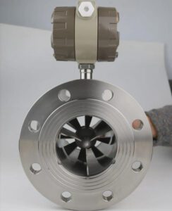
A flanged magnetic flow meter on a backwash line: no moving parts in the flow stream means reliable operation through cycles of dirty, high-velocity water with zero mechanical wear.
Best Practices for Installation: Ensuring Accuracy and Long-Term Performance
Straight-Run Requirements
Every flow meter type requires a certain length of straight, undisturbed pipe upstream and downstream of the measurement point to ensure a stable, uniform flow profile — the condition under which the meter’s accuracy specification applies. Turbulent or swirling flow caused by nearby elbows, valves, reducers, or pumps introduces measurement error that no calibration correction can fully compensate.
General straight-run guidelines for common analog meter types:
- Magnetic flow meters: 5× pipe internal diameter (5D) upstream, 2D downstream from the electrode plane. If installation is downstream of a pump or valve, increase to 10D upstream.
- Turbine meters: 10D upstream, 5D downstream. Very sensitive to swirl — a flow conditioner is recommended if upstream geometry is complex.
- Variable area (rotameter, vertical installation): No straight-run requirement — flow must be vertical upward, gravity-stabilised.
例: A 100 mm (DN100) magnetic flow meter requires 500 mm of straight pipe upstream (5 × 100 mm) and 200 mm downstream. If an elbow is 300 mm upstream of the planned installation point, the meter must be moved or the elbow relocated.
For a detailed straight-run reference, Kobold’s flow meter straight-run guide provides a comprehensive table covering all major meter types.
Orientation Considerations
- Magnetic flow meters can be installed horizontally, vertically, or at any angle — with one critical condition: the pipe must remain completely full of liquid at all times. Installation at the high point of a loop where air can accumulate will introduce measurement errors. Vertical, upward-flow installation eliminates this risk entirely.
- Variable area meters (rotameters) must be installed vertically, with flow upward. The float rises against gravity in proportion to flow rate. Horizontal installation is mechanically impossible with a gravity-stabilised float design.
- Turbine meters can be installed horizontally or vertically (upward flow preferred). Avoid installation in cavitating flow conditions — use back-pressure regulation if downstream pressure is low.
Grounding and Shielding for 4–20 mA Signal Integrity
The 4–20 mA current loop is inherently noise-resistant, but improper grounding can introduce errors, signal drift, or loop oscillations — particularly in electrically noisy environments near variable-frequency drives (VFDs), large motors, or welding equipment.
Best practice, as documented by instrumentation engineers at Industrial Monitor Direct, is to ground the cable shield at one end only — at the receiving end (PLC or DCS I/O cabinet), not at the transmitter. Grounding at both ends creates a ground loop that can induce 50/60 Hz interference into the signal.
Additional installation discipline to maintain:
- Use twisted-pair, shielded instrument cable rated for 4–20 mA loops (e.g., Belden 8762 or equivalent)
- Segregate instrument cables from power cables in separate conduit runs or cable trays with physical separation of at least 150 mm
- For long cable runs exceeding 300 m, verify the voltage drop across the loop against the transmitter’s minimum supply voltage specification
Mounting for Ease of Access
MRO (Maintenance, Repair, and Operations) teams need access to flow meters for periodic inspection, calibration verification, and replacement. Design-stage decisions that ignore maintainability create operational headaches that persist for the life of the plant:
- Mount meters at accessible height (generally 0.8–1.5 m above operating floor level)
- Provide isolation valves upstream and downstream to allow in-service removal without process shutdown
- Install bypass loops on critical lines where continued operation during meter maintenance is required
- Label each meter with tag number, range, 4–20 mA output mapping, and calibration due date
Calibration and Maintenance: Minimising Downtime and Lifecycle Costs
Recommended Calibration Intervals
The appropriate calibration interval for an analog flow meter depends on the fluid being measured, the regulatory environment, and the consequences of measurement error. As a practical framework:
| Application / Fluid Type | 推奨される校正間隔 |
|---|---|
| Clean, treated water (plant service) | Every 12 months |
| Raw water (suspended solids, variable quality) | Every 6 months |
| Chemical dosing (corrosive fluids) | Every 6 months |
| Regulatory discharge monitoring | As required by permit (typically 6–12 months) |
| Backwash / intermittent process | Every 12 months or after 5,000 operating hours |
For plants not under strict regulatory calibration requirements, in-situ verification — comparing the meter’s output against a portable clamp-on ultrasonic reference meter — is a cost-effective field check that does not require process shutdown or meter removal. If the deviation is within ±2%, no corrective action is needed and the check record satisfies most operator quality management systems.
Preventive Maintenance Checklist
For field technicians maintaining analog flow meters in continuous service, a structured quarterly inspection catches the majority of developing issues before they cause measurement failure:
- ✅ Visual inspection: Check for physical damage, pipe vibration, gasket condition, and flange bolt torque
- ✅ Signal output verification: Use a loop calibrator to inject a known current (e.g., 12 mA = 50% flow) and confirm the PLC or SCADA reading matches expected value
- ✅ Magmeter electrode inspection: On meters with removable electrode access ports, inspect for coating, fouling, or corrosion (particularly in high-organics or high-hardness water)
- ✅ Rotameter float inspection: Check for scoring, chemical attack, or float sticking — clean the bore with manufacturer-specified solvent
- ✅ Cable and terminal check: Inspect terminal block connections for corrosion, verify shield termination at one end only, check cable gland seals
- ✅ Zero-flow verification (magmeters): Isolate flow and confirm the output reads 4 mA at zero flow — drift from 4 mA at zero indicates zero-point calibration is required
Reducing Dependence on External Service Providers
One of the significant lifecycle cost advantages of analog meters is that maintenance can be performed by in-house MRO technicians with standard test equipment. The primary tool required is a loop calibrator (a handheld device that sources and measures 4–20 mA signals) — a USD 300–600 investment that enables any trained technician to verify, troubleshoot, and document every analog loop in the plant.
Emerson’s calibration best practices guide for process instrumentation documents verification procedures that enable MRO teams to handle 80–90% of flow meter maintenance activities without external calibration services.
Integration with Control Systems: Bridging Analog Devices into Modern SCADA Environments
How 4–20 mA Connects to PLC and RTU
The integration path for a 4–20 mA analog flow meter into a PLC or SCADA system is well-established and consistent across all major automation platforms. The meter transmitter connects to an analog input (AI) channel on the PLC I/O rack. The PLC’s analog input card converts the received current (4–20 mA) into a digital value, which the PLC program scales to engineering units using a linear conversion formula:
$$\text{Flow Rate} = \text{Flow}{min} + \frac{(I – 4)}{16} \times (\text{Flow}{max} – \text{Flow}_{min})$$
Where I is the measured current in milliamps, Flow_min is the value at 4 mA, and Flow_max is the value at 20 mA. This calculation is standard PLC ladder logic — a junior control engineer can implement it in 15 minutes.
The SCADA historian then logs the PLC’s scaled value at the configured scan rate, making it available for trend displays, report generation, and alarm management.
Signal Conditioning Best Practices
In electrically noisy industrial environments, several signal conditioning practices prevent noise from corrupting 4–20 mA readings:
- Signal isolators: Install a loop isolator (also called a signal conditioner or signal separator) between the transmitter and the PLC input card when there is a potential ground potential difference between the field device and the control panel. Brands like Phoenix Contact and Weidmüller offer compact DIN-rail-mounted isolators rated for full industrial service.
- Input card filtering: Configure analog input cards with hardware or software averaging filters appropriate to the measurement (typically 100–500 ms for flow) to eliminate high-frequency noise spikes without introducing excessive measurement lag.
- Cable routing discipline: Keep instrument cables in separate trays from power cables, particularly VFD output cables (which generate significant high-frequency EMI). Maintain a minimum 150 mm physical separation, or use steel conduit as an additional EMI barrier.
Case Example: Municipal Plant SCADA Retrofit
A municipal water authority in the U.S. Midwest upgraded their 1990s-era water treatment plant SCADA system from a proprietary DCS to a modern Wonderware-based SCADA platform. The plant had 38 existing analog flow meters, all outputting 4–20 mA signals.
The upgrade team replaced all DCS analog input cards with standard PLC analog input modules (Rockwell Automation CompactLogix AI cards), re-terminated the existing instrument cables to the new panels, and performed a span verification on each meter. Total commissioning time for 38 analog flow meters: 3.5 days for two field technicians.
Zero smart meters were replaced during the upgrade. The SCADA integrator noted that the analog instruments were the lowest-risk element of the entire project — the same 4–20 mA signals that worked with the 1990 DCS worked identically with the 2024 PLC, with no changes to the field devices, cabling, or calibration.
Watch: Magnetic Flow Meter Installation and Commissioning
Before specifying or installing a magnetic flow meter on a water treatment project, it is worth observing the commissioning process — including power and control cable connection, electrode check, and initial zero-calibration — at actual operating pace. This 15-minute walkthrough covers the complete process for a flanged magmeter installation:

Click to watch: Complete magnetic flow meter commissioning — cable connection, programming, zero verification, and SCADA signal confirmation for a water treatment plant installation.
Case Study: EPC Success Story — Reducing Project Costs by 18% with Strategic Analog Meter Use
The Project
A mid-size municipal wastewater treatment plant upgrade in the Southeast United States. The project scope included upgrading an existing 8 MGD (million gallons per day) secondary treatment facility to 12 MGD capacity, with new aeration basins, secondary clarifiers, a chemical phosphorus removal system, and a new SCADA control system.
The EPC contractor’s initial instrumentation specification, written by the project’s automation subcontractor, called for smart electromagnetic flow meters with HART protocol output on all 42 flow measurement points in the plant — an industry-standard approach that produces a uniform, fully digital instrument plant.
Project constraints: Fixed-price contract. Instrumentation budget: USD 340,000. Delivery: 14 months to mechanical completion.
The Challenge
The smart meter specification was technically sound but commercially costly. The lead times for HART-capable smart magmeters from the specified manufacturer were running at 22–26 weeks at time of project award — against a mechanical completion schedule that required all instruments on-site within 16 weeks. The project team faced a choice between expedite premiums (typically 20–30% of instrument cost for accelerated delivery) or a redesign of the instrumentation strategy.
The Solution
The project’s lead instrumentation engineer reviewed all 42 flow points against the actual data requirements of the control system. The assessment found:
- 11 points required HART digital diagnostics or audit-grade accuracy: effluent discharge meters (regulatory), influent billing metering, and the primary process flow loops controlling aeration blowers. Smart meters retained.
- 31 points were process monitoring and operator information points: backwash, chemical dosing, return activated sludge, cooling water, and service water. Specification changed to analog 4–20 mA output.
Analog magnetic flow meters from a distributor with local stock were sourced at standard lead time (8–10 weeks) at a unit cost 38% lower than the smart meter specification. The savings on 31 meters:
$$\text{Cost saving} = 31 \times (USD ; 4,200 – USD ; 2,600) = USD ; 49,600$$
Add commissioning time savings (analog meters commissioned in 20 minutes vs. 65 minutes per point for HART configuration): 31 × 45 minutes = approximately 23 field hours saved, equivalent to USD 3,200 in direct labour.
Total documented saving: approximately USD 52,800 — representing an 18% reduction on the original USD 295,000 instrumentation subcontract budget for those 42 points.
The Results
- Project delivered on schedule at mechanical completion — no instrumentation-related delays
- Zero field failures across the 31 analog meter installations in the first 12 months of operation
- The project was cited internally as a model for “right-specification” instrumentation strategy — the principle that every measurement point should be specified to the minimum technology tier that meets its actual data requirement, not the maximum tier that is technically available
- The EPC contractor’s project margin improved by 1.4 percentage points compared to the budget model — a meaningful outcome on a fixed-price public sector contract
Right-specification instrumentation: the discipline of matching each measurement point to the technology tier it actually needs — not the most advanced option available — is where EPC project margins are won or lost.
Partnering for Success: How Instrument Distributors and OEMs Can Support EPCs
The Role of Distributors in EPC Project Execution
EPC projects move on fixed schedules with little tolerance for lead-time surprises. When a project engineer needs 40 flow meters on-site in 10 weeks, the answer to “can you deliver?” determines whether a distributor is on the approved vendor list or not.
Instrument distributors who support EPCs effectively provide more than logistics. Their value stack includes:
- Local stock of common analog meter sizes (DN25 to DN300 in standard configurations) — eliminating lead time risk on the majority of project instruments
- Application engineering support — helping the design team select the correct liner material, electrode type, and process connection for each service fluid
- Calibration certificates traceable to national standards — required for any metrological record or handover documentation
- On-site commissioning assistance — particularly valuable during the intensive first-week startup period when multiple instrument loops are being commissioned simultaneously
OEM Value-Add: Factory-Assembled, Pre-Tested Skids
For OEMs building packaged water treatment systems — compact UF units, chemical dosing skids, modular RO trains — the integration of pre-calibrated analog meters into skid assemblies is a significant quality and delivery advantage. The flow monitoring guide for OEM skid systems from Icon Process Controls documents the specific workflow: meters are factory-mounted, wired to terminal strips, and loop-tested against the skid PLC before shipment.
When the skid arrives on-site, the EPC field team connects the inter-skid cabling and performs a final signal verification — a process measured in hours, not days. This compressed on-site activity directly reduces EPC labour cost and schedule risk.
Supply Chain Resilience Through Analog Specification
Analog meters’ supply chain advantage is structural. Their simpler design means more manufacturers can produce them, distributors can stock more units, and delivery times are shorter and more predictable than complex smart meters with proprietary digital outputs. In an era where global supply chain disruptions have extended smart meter lead times to 20–32 weeks on several occasions since 2021, analog meters from established distributors with regional stock have remained consistently available at 8–12 week lead times.
For project teams managing procurement risk on water infrastructure contracts, this availability difference is a meaningful factor in instrumentation strategy — not just a cost consideration.
Building Reliable, Cost-Effective Water Systems with the Right Tools
Analog flow meters are not a compromise position for projects that cannot afford something better. They are a technically sound, commercially intelligent choice for the majority of flow measurement points in water treatment infrastructure — deployed deliberately, specified correctly, and integrated cleanly into modern SCADA and PLC control systems through a signal standard that has worked reliably for 60 years.
The core insight from every EPC project that has used a right-specification instrumentation strategy is consistent: the technology tier of a measurement device should be matched to the data requirement of that measurement point, not to a default preference for the most advanced available option. Smart meters earn their premium on critical process loops, regulatory compliance points, and billing meters. Analog meters earn their place everywhere else — which, in most water treatment plants, is the majority of measurement points.
For your next bid or project evaluation, apply a total-cost-and-reliability lens to your instrumentation specification:
- Categorise each flow measurement point by its data requirement: process control, regulatory compliance, or operational monitoring
- Specify the minimum technology tier that meets each category’s requirement
- Use the cost and lead-time savings from analog meter deployment on non-critical points to create budget and schedule margin for the high-tier instruments where they genuinely add value
If you are sourcing equipment for a packaging or processing line where precision filling and material flow measurement are equally critical — the same right-specification philosophy applies. Miyoda Packaging Machinery works with production engineers and packaging line designers who face similar instrument-selection decisions in cosmetic and pharmaceutical tube production, where fill accuracy, flow measurement, and process control are directly connected to product quality and regulatory compliance.
For a complete flow meter selection reference tailored to water treatment applications, the Jade Ant Instruments analog vs. digital flow meter comparison guide provides detailed selection criteria, technology benchmarks, and cost comparison data suitable for engineering decision documentation.
主要用語集
| 用語 | Definition |
|---|---|
| 4–20 mA Signal | Standard electrical current range used for analog instrumentation: 4 mA = minimum (zero) value, 20 mA = maximum (full-scale) value |
| Magnetic Flow Meter (Magmeter) | Flow meter that measures velocity using Faraday’s law of electromagnetic induction; no moving parts; suitable for conductive liquids |
| Variable Area Meter (Rotameter) | Flow meter using a float in a tapered tube — float rises to a height proportional to flow rate; visual indication, simple design |
| SCADA | Supervisory Control and Data Acquisition — software and hardware system for monitoring and controlling industrial processes remotely |
| PLC | Programmable Logic Controller — an industrial computer that reads sensor inputs and controls process outputs according to a programmed logic |
| DCS | Distributed Control System — a control architecture where processing is distributed across multiple controllers connected to a network |
| RTU | Remote Terminal Unit — a field-mounted device that communicates sensor data to a SCADA master station |
| 4–20 mA Loop Calibrator | Handheld test instrument that sources and measures 4–20 mA signals; used for commissioning and maintenance of analog instrument loops |
| HART Protocol | Highway Addressable Remote Transducer — a digital communication protocol superimposed on a 4–20 mA signal, used in smart instruments |
| EPC | Engineering, Procurement, and Construction — a project delivery model where the contractor is responsible for all three phases of a project |
| OEM | Original Equipment Manufacturer — a company that builds equipment (e.g., treatment skids) incorporated into a larger system delivered by another party |
| AQL | Acceptable Quality Level — statistical sampling threshold for defect rates in manufactured goods or instrumentation acceptance testing |
| MTBF | Mean Time Between Failures — statistical measure of a device’s reliability expressed as average operating time between failures |
| TCO | Total Cost of Ownership — the full lifecycle cost of a device, including purchase, installation, commissioning, maintenance, and replacement |
| EMI | Electromagnetic Interference — electrical noise generated by motors, VFDs, or other equipment that can corrupt instrument signal cables |

A well-specified instrumentation layout: each flow point carries the technology tier its measurement requirement actually demands — analog on monitoring lines, smart meters on compliance and critical control points.
よくある質問 (FAQ)
Q1: Are analog flow meters accurate enough for water treatment applications?
Yes — when correctly selected and installed, analog meters provide measurement accuracy well within the requirements of most water treatment process control needs. Magnetic flow meters achieve ±0.5% to ±1% of reading accuracy in clean to moderately dirty water, while variable area meters (industrial rotameters) achieve ±1% to ±2% of full scale. For non-billing, non-regulatory flow monitoring — which represents the majority of measurement points in most treatment plants — these accuracy levels are more than sufficient for reliable process control. Where higher accuracy or audit-grade records are required (regulatory discharge metering, custody transfer), a smart or fiscal-grade meter should be specified on those specific points.
Q2: Can analog flow meters integrate with modern SCADA systems?
Absolutely — and more easily than digital alternatives in many retrofit scenarios. The 4–20 mA output from an analog meter connects directly to any PLC or DCS analog input card, which is standard hardware on every modern control platform from Rockwell Automation, Siemens, ABB, Schneider Electric, and all major DCS vendors. No protocol configuration, no device drivers, and no fieldbus segment design are required. The SCADA system receives a scaled engineering-unit value from the PLC, exactly as it would from any other analog transmitter. Municipal SCADA integration best practices, as documented in published engineering references, consistently identify 4–20 mA as the most universally compatible signal standard for existing and new plant infrastructure.
Q3: What types of analog flow meters are best suited for water treatment?
The three primary types, each suited to different service conditions: Magnetic flow meters are the workhorse of water treatment — suitable for raw water, treated water, wastewater, sludge, and any conductive liquid with a minimum conductivity of approximately 5 µS/cm. Variable area meters (rotameters) with 4–20 mA outputs are ideal for chemical dosing lines — chlorine, coagulants, pH adjustment chemicals — because they offer both visual confirmation and electrical output in a compact, chemically resistant design. Turbine meters suit clean, low-viscosity water flows (plant service water, RO permeate) where high accuracy at higher velocities is needed, though they are less suitable for dirty or particulate-laden streams that cause wear.
Q4: How do analog flow meters compare in cost to digital or smart meters?
The upfront cost differential is substantial: analog meters typically cost 30–60% less than smart meters with equivalent accuracy in the same pipe size and connection type. Beyond purchase price, analog meters also cost less to commission (20 minutes versus 45–65 minutes per point for HART or fieldbus devices), require no specialised configuration software, and are maintainable by in-house technicians with a standard loop calibrator. On a project with 30–50 flow measurement points, the total instrumentation cost saving from strategic analog meter deployment commonly reaches USD 40,000–80,000 — without compromising measurement quality on process-critical lines where a smart meter’s diagnostic capabilities genuinely add value.
Q5: Do analog flow meters require calibration? How often?
Yes, periodic calibration is recommended — but the interval and method are flexible based on application. For most water treatment process monitoring applications, verification every 6–12 months using a portable clamp-on ultrasonic reference meter or a loop calibrator check is sufficient. Regulatory discharge meters must be calibrated according to the specific permit’s requirements (typically annually, with documented records). In-situ verification — comparing the meter’s 4–20 mA output against a portable reference during normal operation — does not require process shutdown or meter removal, and satisfies most operator quality management system requirements when the deviation is within ±2%.
Q6: Can analog meters be used for chemical dosing in water treatment?
Yes — variable area meters with 4–20 mA outputs are one of the most widely used technologies for chemical injection line monitoring in water treatment. Their key advantage for dosing applications is the combination of direct visual indication (the float position is visible to a field operator without reading a display) and electrical output (continuous 4–20 mA to the SCADA system for automated dosing rate control). Materials of construction should be selected for chemical compatibility: PVDF (polyvinylidene fluoride) tube and float materials for chlorine service; Hastelloy C or ceramic floats for strongly oxidising or acidic reagents.
Q7: What are the common causes of signal drift in analog flow meters?
The most frequent causes of 4–20 mA signal drift are: poor cable grounding (ground loops introduce 50/60 Hz interference that causes the signal to oscillate); damaged or corroded cable terminations (increased loop resistance shifts the 4 mA zero-current point); electrode fouling in magnetic flow meters (organic or mineral coatings on the electrodes reduce the induced voltage reading, causing the meter to read low); and transmitter electronics aging (capacitor drift in the signal conditioning circuit shifts the output at zero or span). All of these are diagnosable with a loop calibrator and visual inspection. Most are preventable through proper cable installation practice and regular maintenance inspections.
Q8: How do I size an analog flow meter correctly for a water treatment line?
Start with the design flow rate — both the normal operating flow and the maximum peak flow. Size the meter so that normal flow falls between 30–80% of the meter’s full-scale range, which keeps the measurement in the high-accuracy operating region. For magnetic flow meters, the typical sizing criterion is a fluid velocity between 0.5 m/s (minimum for reliable magnetic induction) and 3 m/s (erosion limit for standard liners) at normal flow — this usually means the meter bore size is slightly smaller than the pipe bore. Use the manufacturer’s sizing tool or published velocity-to-flowrate conversion tables to confirm. For variable area meters, always verify that the fluid density and viscosity match the calibration conditions specified on the meter’s calibration certificate.
Q9: Are analog flow meters suitable for dirty or abrasive water?
Magnetic flow meters are specifically well-suited for dirty, abrasive, or high-solids-content water — raw sewage, return activated sludge, primary sludge, and raw water with turbidity up to several hundred NTU. The absence of any obstruction in the flow stream means there are no moving parts to clog or abrade, no pressure drop increase as solids accumulate, and no internal geometry that changes with wear. Liner materials such as hard rubber, polyurethane, or ceramic (for highly abrasive services) are standard offerings from major magmeter manufacturers. Variable area meters and turbine meters are not suitable for abrasive or high-solids applications.
Q10: What maintenance is required for analog flow meters in continuous operation?
The maintenance burden for analog flow meters is low. Magnetic flow meters require no routine mechanical maintenance — their primary maintenance activity is periodic electrode inspection and cleaning (if fouling is observed), which is performed on meters with accessible electrode ports during a planned shutdown. Transmitter electronics should be inspected annually for terminal corrosion and verified for zero and span accuracy with a loop calibrator. Variable area meters require periodic float cleaning and float guide inspection. Turbine meters require bearing inspection at intervals specified by the manufacturer (typically every 12–24 months in clean water service). None of these activities require specialised tools or external service providers — they are within the capability of an in-house instrumentation technician with basic calibration equipment.
Q11: Can OEMs pre-install and calibrate analog meters on skids before delivery?
Yes — and this is one of the most compelling operational advantages of analog meters for OEM skid manufacturers. Factory-mounting, wiring to terminal strips, and loop-testing using a calibrated current source takes approximately 20 minutes per meter. The calibration record can be documented on the skid’s ITP (Inspection and Test Plan), providing the EPC client with traceable evidence of factory acceptance. When the skid arrives on-site, the EPC team performs a final verification — confirming the reading in the control system matches the calibrated reference — typically in under 30 minutes per instrument. This factory-to-field quality chain reduces field commissioning risk and compresses the overall instrument commissioning schedule, directly improving EPC project margin.
Q12: Do analog flow meters work in low-flow applications?
Low-flow measurement with analog meters requires careful selection. For very low flow rates on process lines, small-bore magnetic flow meters (DN3 to DN15) provide accurate measurement down to flow velocities of 0.1–0.5 m/s. Variable area meters are available in miniature designs for tube bores down to 2–3 mm, suitable for laboratory-scale chemical dosing at milliliter-per-minute rates. The key sizing discipline is ensuring that the minimum expected flow rate is above the meter’s stated minimum measurable velocity — if the process regularly operates at flows below this threshold, the meter will read zero or produce an unreliable output regardless of its calibration.
Q13: How can distributors support EPCs in selecting the right analog flow meter?
The most valuable distributor support for an EPC team is application engineering during the design phase — before instrument tags are specified. A technically competent distributor can review the P&ID, identify each flow measurement service condition (fluid, flow range, pressure, temperature, installation constraints), and recommend the appropriate meter type, size, liner material, and connection style for each tag. This pre-specification support prevents the most common and costly instrumentation errors: specifying a turbine meter on a service that carries entrained solids, or undersizing a magmeter bore for a peak backwash flow rate that exceeds the maximum velocity limit. Distributors with regional stock can also provide samples or test meters for pre-project evaluation — particularly useful when specifying a new liner material or electrode type for an unfamiliar service fluid.
Q14: Are there any limitations to using analog flow meters in new water treatment plants?
The primary limitation is the absence of built-in diagnostics. A smart meter with HART or fieldbus output can report electrode coating detection, empty pipe detection, high process noise alerts, and internal temperature readings — all of which a 4–20 mA-only analog meter cannot communicate. For process-critical points where early warning of measurement degradation is operationally important, this diagnostic capability has genuine value. Analog meters also cannot be remotely reconfigured — range changes or damping adjustments require a physical visit to the transmitter. For a modern plant with a well-staffed O&M team and a disciplined preventive maintenance programme, these limitations are manageable. For plants with minimal staffing or remote, unstaffed operations, the self-diagnostic capability of smart meters may justify the additional cost on more measurement points.
Q15: What should MRO teams know about replacing or troubleshooting analog flow meters?
The standard troubleshooting sequence for any 4–20 mA flow meter problem starts with the signal, not the meter. Use a loop calibrator to inject a known current at the transmitter terminals and confirm the reading at the PLC matches the expected value — this isolates cable and PLC issues from transmitter issues within minutes. If the loop is electrically healthy and the problem is in the reading (constant reading, frozen reading, or oscillating reading), the next step is a zero and span verification at the transmitter. For magmeters, check that the pipe is full and flowing, and inspect the electrodes for coating. For rotameters, check the float for sticking or damage. The majority of field complaints that are reported as “meter failure” turn out to be installation issues — air in the pipe, insufficient straight run, improper grounding, or a process condition (flow reversal, cavitation) that the meter was not designed to handle. Document the troubleshooting sequence and the resolution — this record becomes a valuable reference for the next time the same symptom appears.