Variable area (VA) flow meters — commonly known as rotameters — remain one of the most widely deployed flow measurement devices in industrial settings worldwide. From chemical dosing lines in water treatment plants to purge gas monitoring in semiconductor fabs, VA meters have earned their place through mechanical simplicity, visual readability, and broad fluid compatibility. According to industry data, the global flow meter market was valued at USD 9.1 billion in 2024, and variable area meters continue to hold a significant share in applications where cost-effective, reliable measurement is required.
This guide is written for process engineers, instrumentation specialists, and procurement teams who need to select the right VA flow meter for a specific application — not just any rotameter off the shelf. We will walk through every critical decision point: operating specifications, material and fluid compatibility, pressure drop implications, sizing calculations, output integration, mounting requirements, calibration strategy, and common selection mistakes that cost thousands in rework.
Whether you are specifying a meter for a new chemical plant or replacing a failing unit on a pharmaceutical clean utility loop, this article provides a field-ready framework. ジェイド・アント・インストゥルメンツ has compiled this resource from real-world installation data across chemical, water, oil & gas, and food-grade applications to help you avoid the costly trial-and-error approach that plagues too many meter selection projects.
可変面積式流量計とは何か、その仕組み
VA流量計の基本動作原理
可変面積式流量計は、一見単純に見える原理に基づいて動作します。先細りの管内を上向きに流れる流体がフロートを持ち上げ、上向きの抗力と浮力が、フロートの下向きの重力と等しくなるまで続きます。 その平衡点において、フロートと管壁の間の環状断面積は体積流量に比例します。校正済みの目盛りを参照して読み取るフロートの位置により、外部電源を必要とせずに、即座にリアルタイムの流量表示が得られます。.
この現象の背後にある物理的原理は、ベルヌーイの式と力の平衡に基づいています。流量が増加すると、テーパー管内のフロートが上昇し、流体が通過する断面積が大きくなります。フロート両端の圧力降下は、測定範囲全体を通じて実質的に一定に保たれます。この特性こそが、VAメーターを他のメーターと区別する点であり、 ISO 5167に準拠した差圧測定装置, where the pressure drop varies with flow.
液体の場合、浮力と流速ヘッドの両方がフロートの持ち上げに寄与します。気体の場合、浮力は無視できるほど小さく、フロートの動きはほぼ完全に流速ヘッドによって決まります。この違いは計器の選定において極めて重要です。水用に校正された計器は、適切な換算係数を適用しない限り、空気では正しい測定値を示しません。.
一般的な構成と流量範囲
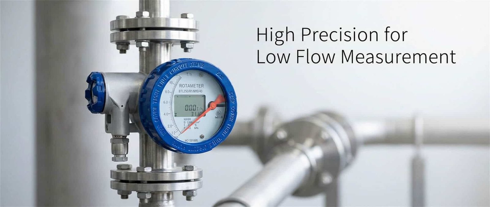
Variable area flow meters come in several distinct configurations, each optimized for different operating conditions. Glass tube rotameters — the most recognizable type — use precision-formed borosilicate glass tubes and are suitable for flows up to approximately 60 GPM (water) or 200 SCFH (air), with pressure ratings typically up to 500 psig for small diameters. Metal tube rotameters use stainless steel, Hastelloy, or Monel tubes with magnetic float followers, extending the operating envelope to 750 psig and 540°C (1,000°F), with flow capacities up to 4,000 GPM water or 1,300 SCFM air. Plastic tube rotameters — typically polycarbonate or acrylic — serve lower-cost applications involving corrosive fluids or deionized water, generally limited to 100 psig and 65°C (150°F).
Beyond the classic rotameter, the VA family includes vane-style meters (spring-opposed vanes responding to flow velocity), piston-type meters (spring-opposed pistons less sensitive to viscosity changes), bypass rotameters (orifice/rotameter combinations for larger pipe sizes), and tapered plug meters (stationary core with a moving piston). The general measurement range for VA meters spans from 0.01 cc/min for precision laboratory instruments up to 4,000 GPM for large industrial metal tube designs — a breadth that few other single-technology families can match.
| 設定 | チューブの材質 | 最大圧力 | 最高温度 | 標準精度 | 最大流量(水) |
|---|---|---|---|---|---|
| ガラス管式ロータメーター | ホウケイ酸ガラス | 500 psig(小口径) | 200°C (400°F) | ±1–5% FS | 60 GPM |
| 金属管式ロータメーター | SS 316 / ハステロイ / モネル | 750 psig | 540°C (1,000°F) | ±1–2% FS | 4,000 GPM |
| プラスチック管式ロータメーター | ポリカーボネート/アクリル | 100 psig | 65°C (150°F) | ±5% FS | 30 GPM |
| バイパス式ロータメーター | ガラスか金属か | Varies by orifice | 場合による | ±5% FS | 大口径パイプ |
| ベーン/ピストン式 | 金属製ボディ | 1,000 psig | 260°C (500°F) | ±2–5% FS | 場合による |
考慮すべき主な仕様
サイズ、測定範囲、精度――これらが測定に与える影響
The first specification engineers reach for is typically accuracy — but in VA flow meter selection, the relationship between meter size, measurement range, and accuracy is tightly coupled and frequently misunderstood. Standard industrial rotameters are specified at ±1–2% of full scale (FS) over a 10:1 turndown, while laboratory-grade units can achieve ±0.5% of actual reading (AR) over a 4:1 range. The critical distinction: percent of full scale means error is fixed relative to maximum flow, so at 20% of scale, a ±2% FS meter has an effective error of ±10% of reading. This makes meter sizing — not just meter accuracy class — the dominant factor in real-world measurement performance.
A common field scenario illustrates the point: a pharmaceutical plant specified a DN25 metal tube rotameter rated at 0–100 LPM for a cooling water line that normally runs at 15–25 LPM. The meter’s ±2% FS specification translated to ±2 LPM uncertainty — roughly 8–13% of the actual reading. Downsizing to a DN15 meter rated at 0–30 LPM with the same ±2% FS accuracy reduced uncertainty to ±0.6 LPM, or approximately 2.4–4% of reading. Same accuracy class, dramatically different real-world performance — all driven by proper sizing.
分解能、再現性、および応答時間
VAメーターの分解能は、目盛りの刻みと、浮子の位置を読み取る観察者の能力によって決まります。ガラス管式の場合、通常、フルスケールの約1%程度です。 磁気式フォロアとポインタ式指示器を備えた金属管式メーターも同様の分解能を有していますが、位置トランスミッタを搭載したモデルでは、0.5% FS以上の分解能を実現できます。.
再現性――すなわち、同じ流量条件下で同じ測定値を再現できる計器の能力――は、VAメーターの強みです。 適切にメンテナンスされたロータメーターは、実流量の±0.25%という再現性を達成できるため、オペレーターがフロートの位置を見ながらバルブを調整する手動流量設定用途に適しています。 直読式のガラス管設計では、応答時間は本質的に高速です(フロートは 1~2 秒以内に反応します)。一方、トランスミッタを装備した金属管ユニットでは、ダンピング設定に応じて 0.5~3 秒の信号処理遅延が生じる場合があります。.
流体との適合性と材料の選定
温度限界および化学的適合性
Fluid temperature directly affects both the meter body and the measurement. For glass tube rotameters, the practical ceiling is approximately 200°C (400°F), but operating at elevated temperatures substantially derates the pressure rating — a relationship that is roughly linear. At 200°C, the safe working pressure of a standard borosilicate glass tube may drop to 30–50% of its room-temperature rating. Metal tube rotameters extend the envelope to 540°C (1,000°F) with stainless steel construction, and specialty alloys like Hastelloy C-276 or Monel 400 push chemical compatibility into aggressive acid and chloride-bearing environments.
Chemical compatibility failures account for a disproportionate share of VA meter field problems. Wet steam and high-pH water above 90°C can soften borosilicate glass. Caustic soda (NaOH) dissolves glass over time. Hydrofluoric acid etches glass rapidly. These are not theoretical risks — a water treatment plant in the U.S. Midwest documented a case where glass rotameters on a 12% NaOH dosing line required replacement every 4–6 months until the plant switched to PTFE-lined metal tube meters, which have now run for over 3 years without tube degradation.
接触材料の選択肢と腐食に関する考慮事項
The “wetted parts” of a VA meter include the tube, float, packing/O-rings, and end fittings. Each must be independently compatible with the process fluid. Float materials range from 316 stainless steel (general purpose) through Hastelloy, tantalum (excellent for hot sulfuric acid), sapphire, and carboloy (tungsten carbide — for abrasion resistance). O-ring and packing materials include Buna-N (general hydrocarbons), Viton (high temperature, aggressive chemicals), PTFE (broadest chemical resistance), and Kalrez (extreme chemical/thermal environments).
超高純度半導体用化学薬品や反応性の高いフッ素ガスなど、特殊な金属材料でさえ不十分な用途においては、全PTFE製またはPFAライニング加工された流量計が、完全に不活性な流路を実現します。. Jade Ant Instruments’ flow meter selection methodology 技術の選択肢を絞り込む前に、プロセス流体の化学組成、濃度、および使用温度に対して、接触する材料の適合性を体系的に評価する。.
| 素材 | 最適 | 避けるべきもの | 最高温度(概算) |
|---|---|---|---|
| 316ステンレス鋼 | 水、弱酸、一般的な化学物質 | Chloride stress cracking, HCl | 540°C |
| ハステロイ C-276 | 強酸、塩化物、酸化性媒体 | Dry chlorine gas at high temp | 540°C |
| タンタル | 熱硫酸、塩酸、およびほとんどの酸 | HF, strong alkalis, fuming sulfuric | 300°C |
| PTFE/PFAライニング | 超高純度流体、HF、強アルカリ | 溶融アルカリ金属、高温のフッ素 | 260°C |
| ホウケイ酸ガラス | 水、空気、低濃度の有機物、目視による確認 | NaOH, HF, wet steam >90°C | 200°C |
圧力損失、流量範囲、および設置上の考慮事項
圧力損失がプロセスおよびエネルギー使用に及ぼす影響
One of the key advantages of VA flow meters is their relatively constant and predictable pressure drop — typically in the range of 0.1–0.5 bar depending on the meter size, float type, and flow rate. Unlike orifice-plate systems where pressure loss increases with the square of flow, a properly sized VA meter maintains a nearly fixed differential across the float.
However, “low” does not mean “free.” In a petrochemical plant running 24/7, a VA meter creating 0.3 bar pressure drop on a 4-inch cooling water line flowing at 500 GPM translates to approximately 0.75 kW of continuous pumping power — roughly USD 550/year in electricity at average U.S. industrial rates. Over a 10-year service life, that single meter’s pressure drop costs over USD 5,500, often exceeding its purchase price. For energy-conscious facilities, comparing the permanent pressure loss across candidate meters is not optional — it is part of the economic decision. Jade Ant Instruments のインストールに関するベストプラクティスガイド この計算を行うための圧力損失計算シートが含まれています。.
配置、直通配管の要件、および配管に関する考慮事項
VA流量計は、他の多くの技術に比べて設置上の大きな利点があります。それは、上流側の配管における乱れの影響をほとんど受けないという点です。 電磁式、超音波式、または渦式流量計では、上流側にパイプ径の10~40倍に相当する直管区間が必要となる場合がありますが、ロータメーターは、測定精度の著しい低下を招くことなく、パイプのエルボの直後に設置することができます。これは、フロートが環状隙間全体にわたる流速分布を統合し、流れを効果的に自己平均化するためです。.
That said, gravity-operated VA meters (the vast majority of rotameters) must be mounted vertically with flow entering from the bottom. Deviations from true vertical — even 2–3 degrees — introduce systematic reading errors because the float’s equilibrium position shifts. Spring-loaded VA meter designs eliminate this constraint and allow horizontal or angled mounting, but they sacrifice the passive (no-power) advantage of gravity-type units. For installations where headroom is limited, bypass rotameters using an orifice plate in the main line and a small rotameter in a parallel sampling line offer a practical alternative.
選定のヒント:必要流量の算出と選定
VAメーターの電流経路と電流密度の推定方法
Correct sizing of a VA flow meter requires converting your actual process flow to the meter’s calibration reference — typically water for liquids and air at standard conditions for gases. Manufacturers provide sizing tools, nomographs, or software for this conversion, but the underlying math is straightforward. For liquids, the water-equivalent flow rate is calculated by multiplying the actual volumetric flow by the square root of the ratio of the calibration fluid’s specific gravity to the actual fluid’s specific gravity. For gases, the air-equivalent flow rate requires accounting for both the actual gas density (which depends on molecular weight, temperature, and pressure) and the float material density.
A critical mistake in gas applications is ignoring the operating pressure and temperature. A meter sized for nitrogen at 20°C and 1 bar will read roughly 40% low if the actual operating condition is 3 bar absolute — because the gas density triples, and the float rises less for the same mass flow. Always specify the actual operating conditions, not “standard” conditions, when requesting manufacturer sizing assistance.
安全余裕を考慮した計測範囲の選定
一般的な推奨事項として、フルスケール範囲において、通常の運転流量がフルスケールの40%から70%の範囲内になるような流量計を選択することが挙げられます。 この「スイートスポット」は、起動時、洗浄サイクル中、またはプロセスの異常時における流量の変動に備えた余裕を確保しつつ、有効精度を最適化します(フルスケールに基づく誤差が、スケール中央部では読み値に対する割合が小さくなるため)。.
Undersizing is dangerous: if the flow occasionally exceeds the meter’s maximum, the float can slam into the top stop, potentially damaging the tube or jamming the float mechanism. Oversizing is wasteful: at 10% of full scale, a ±2% FS meter produces ±20% reading error, making the measurement essentially meaningless for process control. The dual-ball rotameter — using a light float for low-flow indication and a heavy float for high-flow indication — extends the usable range when the process has a very wide flow window. For example, one dual-ball design covers 235–5,000 mL/min in a single tube.
Video: Variable Area Flowmeters – Working Principle, Animation, and Manufacturing (Source: YouTube)
出力オプションとシステムとの連携
アナログ出力とデジタル出力、トランスミッタ、および信号伝送
基本的なガラス管式VAメーターは、現地表示専用の装置であり、操作者はガラス管の目盛りを参照してフロートの位置を目視で確認します。 遠隔表示、データロギング、または制御システムとの連携が必要な場合は、位置トランスミッタを備えた金属管式ロータメーターが標準的な選択肢となります。これらのトランスミッタは、磁気結合(フロート内に磁石が内蔵されており、外部センサーがその垂直方向の動きを追跡する)によってフロートの位置を検出し、それを標準出力信号に変換します。.
The most common output is 4–20 mA analog, which is universally compatible with PLCs, DCS systems, chart recorders, and panel meters. For digital integration, transmitters are available with HART protocol overlay (on the 4–20 mA signal), enabling remote configuration, diagnostics, and multi-variable data retrieval without additional wiring. Some modern VA transmitters also support Foundation Fieldbus or Profibus PA for full digital bus integration in large plant architectures. Alarm contacts (high/low flow switches) and pulse outputs for totalization are available as additional features on many industrial metal tube rotameters.
インターフェースプロトコルおよび電気的要件
危険区域向けにトランスミッタ付きVAメーターを指定する場合、保護方式(本質安全防爆(Ex ia/ib)、防炎型(Ex d)、または非発火型)によって、許容される配線方法、バリアの種類、および電源の特性が決まります。 VAトランスミッタには、現場での配線が簡素化され、メンテナンスも容易になるため、本質安全型設計が最も一般的です。電源要件は通常、それほど厳しくありません。4~20 mA/HART対応ユニットの場合、12~30 VDCのループ給電で、消費電流は22 mA未満です。設置場所が IEC 60079 に分類される危険区域, ensure the complete loop — meter, barrier, cable, and junction box — is certified as a system, not as individual components.
取付、向き、およびプロセス接続
取り付け方式(パネル型、インライン型、サニタリー型など)
VA流量計は、多くのエンジニアが想像するよりも幅広い取り付け構成で提供されています。パネルマウント型ロータメーター(背面にねじ接続を備えたコンパクトなユニット)は、制御盤、ガス分配マニホールド、および分析機器ラックへの組み込みを想定して設計されています。 フランジ、ねじ(NPT/BSP)、または圧縮継手を備えたインライン型は、プロセス配管に直接取り付けることができます。トライクランプ接続と電解研磨仕上げを施したサニタリー/ハイジエン仕様は、以下の要件を満たしています。 3-A衛生基準 for food, beverage, and pharmaceutical applications, where cleanability and material traceability are mandatory.
化学薬品の注入、ガスの混合、実験室設備などでよく見られる、複数の流体の測定を必要とする用途において、マルチチューブ・ロータメーター・ステーションは、1つのフレームに最大6台の個別メーターを、共通の入口・出口マニホールドとともに取り付けることで、設置面積を削減し、配管を簡素化します。.
オリエンテーションおよびボンディング/アースに関する考慮事項
Gravity-type rotameters must be mounted within ±1° of true vertical for rated accuracy. In practice, this means using a plumb reference during installation — not eyeballing. Even well-intentioned installations on skid-mounted systems can develop tilt if the skid’s leveling feet settle unevenly over time. Spring-loaded designs relax this requirement and permit mounting at any angle, including horizontal and inverted, making them suitable for applications where vertical mounting is physically impossible.
For metal tube meters with electronic transmitters, proper grounding is essential to prevent signal noise and measurement drift. The meter body should be electrically bonded to the process piping and the plant’s ground grid. In plastic piping systems (common in chemical and semiconductor plants), dedicated grounding straps or conductive fittings may be required. The ジェイドアントインスツルメンツデータシートガイド メーカーの資料に基づいて接地要件を確認する方法に関するセクションが含まれています。.
校正、保守、および信頼性に関する要因
校正頻度とドリフトに関する考慮事項
VA flow meters are inherently stable devices — there are no electronics to drift in basic glass tube designs, and the mechanical calibration is set by the fixed geometry of the tube taper and the float dimensions. Laboratory rotameters calibrated to ±0.5% AR can maintain that performance for years if the tube and float remain clean and undamaged. Industrial units typically require recalibration every 12–24 months, though the interval depends heavily on the process fluid’s fouling tendency.
からの一般的な指針 フルークの校正に関するベストプラクティス では、校正用標準器は被試験装置よりも少なくとも4倍高い精度を持つべきであると規定されています。±2% FSのロータメーターの場合、これは±0.5%以上の精度を持つ基準標準器を使用することを意味します。 液体の校正は通常、重量法(計量タンク)または容積法(容積式プローバー)を用いて行われ、気体の場合はベルプローバーまたは基準質量流量コントローラを用いて行われます。ほとんどのVAメーターでは、設置場所での検証は現実的ではなく、ベンチ校正のために装置を稼働から外す必要があります。.
保守作業と診断
VA流量計で最もよく見られるメンテナンス上の問題は、フロートの汚染(付着、スケール、または微粒子の堆積)、チューブの曇りや変色(ガラス製モデルの場合、視認性が低下する)、およびOリングやパッキンの劣化(漏れの原因となる)です。 予防的なメンテナンスプログラムには、フロートとチューブの定期的な目視検査(汚れが発生しやすい環境では3~6ヶ月ごと)、状態に応じた、あるいは固定のスケジュールに基づくOリングの交換 (PTFEの場合は年1回、腐食性の強い環境でのブナNの場合は6ヶ月ごと)、およびゼロ点測定値の確認(流量がない状態で、フロートはゼロマークの位置かそれより下に留まっている必要がある)が含まれます。.
One often-overlooked diagnostic: if a rotameter’s reading has gradually drifted upward over time without a corresponding process change, the float may have been eroded by abrasive particles, reducing its mass and causing it to ride higher for the same flow. This is particularly common in slurry-adjacent applications where trace solids pass through. Weighing the float against its original specification weight is a quick and definitive diagnostic. For mission-critical applications, Jade Ant Instrumentsのおすすめ 校正や修理中のダウンタイムを最小限に抑えるため、予備のフロートおよびチューブアセンブリを用意しておく。.
選定ワークフローとよくある落とし穴のチェックリスト
段階的な評価プロセス
An effective VA flow meter selection follows a structured workflow that prevents the most expensive mistakes — those discovered after installation. The process below reflects the decision logic used across 12,000+ meter installations documented by ジェイド・アント・インストゥルメンツ.
Step 1: Define the process fluid. 流体の名称、状態(液体/気体)、比重または分子量、使用温度における粘度、化学組成、および粒子状物質の含有量を記録してください。流体が混合物である場合は、その組成範囲を記録してください。.
Step 2: Establish operating conditions. 流量、圧力、温度の通常値、最小値、最大値を記録してください。設計基準上の最大値を主要なサイズ決定の入力値として使用しないでください。実際の通常の運転範囲を使用してください。.
Step 3: Determine the measurement purpose. Is the meter for visual indication only, manual flow setting, remote monitoring, or closed-loop control? This determines whether a basic glass tube, a metal tube with transmitter, or a transmitter-only (no local indication) configuration is appropriate.
Step 4: Evaluate material compatibility. 流体の化学的性質、濃度、温度と、チューブ、フロート、Oリング、および端部継手の接触材料の選択肢とを照合してください。不明な点がある場合は、メーカーに正式な適合性審査を依頼してください。.
Step 5: Size the meter. プロセス流量を流量計の校正基準(水相当または空気相当)に変換し、通常の運転流量がフルスケールの40~70%の範囲になるような流量計の測定範囲を選択してください。.
Step 6: Specify outputs and mounting. 接続方式(フランジ、ねじ込み、トライクランプ)、取り付け方向(垂直、水平、パネル)、出力信号(ローカルのみ、4~20 mA、HART、パルス)、および該当する場合は危険区域分類を選択してください。.
Step 7: Validate pressure drop. Confirm that the meter’s pressure drop at maximum flow is acceptable within the system’s available differential pressure. This is especially critical for gravity-feed systems and low-pressure gas applications.
VA Flow Meter Application Distribution by Industry
Water & Wastewater (22%)
Pharmaceutical (18%)
Oil & Gas (15%)
Food & Beverage (10%)
Other (5%)
Common Mistakes to Avoid in VA Flow Meter Selection
After reviewing hundreds of field failure reports, the following seven mistakes account for the majority of VA flow meter problems that could have been prevented at the selection stage:
Mistake 1: Sizing based on pipe size instead of flow rate. A DN50 pipe does not automatically require a DN50 meter. The meter size should be determined by the actual flow range, and reducers should be used when the optimal meter size differs from the pipe size.
Mistake 2: Ignoring viscosity effects. VA meters are “relatively insensitive” to viscosity — but this tolerance has limits that vary by float shape and meter size. Small ball-float rotameters are the most viscosity-sensitive. If the process fluid’s viscosity exceeds the manufacturer’s published limit for the selected float, readings must be corrected or a different float/meter combination selected.
Mistake 3: Specifying glass tubes in unsafe environments. If tube breakage could release hazardous fluids or create a safety incident, metal tube meters with magnetic followers are mandatory — regardless of the cost differential.
Mistake 4: Forgetting to account for gas density at operating conditions. A rotameter calibrated for air at standard conditions will read low on compressed gases and high on lighter-than-air gases if no density correction is applied.
Mistake 5: Installing gravity-type meters off-vertical. Even 3° of tilt causes measurable reading error. Use a spirit level during installation and recheck periodically on skid-mounted systems.
Mistake 6: Neglecting downstream backpressure for gas meters. Gas VA meters require a minimum backpressure (typically at least twice the meter’s pressure drop) to ensure the float responds to mass flow rather than just velocity. Without adequate backpressure, readings become unreliable.
Mistake 7: Selecting based on purchase price alone. A USD 150 plastic rotameter that fails every 6 months in a corrosive service costs far more over 5 years than a USD 800 PTFE-lined metal tube meter that runs maintenance-free.
Root Causes of VA Flow Meter Field Failures (%)
Wrong
Sizing
素材
Mismatch
Install
Error
Fouling /
Scaling
Gas Density
Ignored
Other
VA Flow Meter Selection Worksheet (Copy to Excel)
| パラメータ | Your Value | Units | 注記 |
|---|---|---|---|
| Fluid Name | — | Include concentration if applicable | |
| Fluid Phase | Liquid / Gas | Specify if two-phase possible | |
| Specific Gravity (liquid) or MW (gas) | SG / g/mol | At operating temp & pressure | |
| Viscosity | cP | At operating temperature | |
| Normal Flow Rate | GPM / LPM / SCFM | Typical operating flow | |
| Minimum Flow Rate | GPM / LPM / SCFM | Startup / turndown | |
| Maximum Flow Rate | GPM / LPM / SCFM | Peak / upset condition | |
| 動作温度 | °C / °F | Normal and max | |
| Operating Pressure | psig / bar | Normal and max | |
| Required Accuracy | % FS or % AR | Specify basis | |
| Output Signal Required | — | Local / 4–20mA / HART / Pulse / Alarm | |
| 取り付け方向 | — | Vertical / Horizontal / Panel | |
| Hazardous Area Classification | — | Zone / Division / Gas Group / T-Class | |
| Process Connection | — | NPT / Flanged / Tri-Clamp / Compression |
Selecting the right variable area flow meter comes down to three interdependent decisions: matching the meter’s specifications to your actual process conditions (not design maximums), ensuring full material compatibility across every wetted component, and sizing the meter so that normal operating flow falls in the 40–70% range where effective accuracy is strongest. Every other consideration — outputs, mounting style, calibration interval — flows from getting these three fundamentals right.
Before placing an order, validate your selection by reviewing the manufacturer’s datasheet against your completed selection worksheet (Table 3 above), requesting a formal compatibility statement for your specific fluid and conditions, and confirming that the pressure drop at maximum flow is within your system’s available differential. For critical applications, request test data or a trial installation before committing to a fleet purchase.
The most efficient next step: create a shortlist of two or three candidate meters, then engage directly with manufacturers for application-specific sizing, compatibility confirmation, and delivered pricing. Jade Ant Instruments’ engineering team offers free sizing assistance and can provide a detailed quotation package — including GA drawings, material certificates, and calibration scope — within 48 hours of receiving your completed specification form at www.jadeantinstruments.com.

よくある質問 (FAQ)
What distinguishes a variable area flow meter from other flow meters?
A variable area flow meter measures flow by allowing the fluid to lift a float inside a tapered tube — the float position directly indicates the flow rate. Unlike electromagnetic or turbine flow meters that produce electronic signals from the start, a VA meter provides inherent visual indication without requiring external power. This passive operating principle makes it uniquely suitable for applications where electrical power is unavailable, where fail-safe visual monitoring is needed alongside electronic systems, or where budget constraints favor a lower-cost mechanical instrument. The constant pressure-drop characteristic also differentiates it from orifice-plate systems, where pressure loss varies with the square of flow.
How do I determine the appropriate meter range for my process?
Start by documenting three flow values: your minimum operating flow (startup, low-load, or night-shift conditions), normal operating flow, and maximum expected flow (including upset or cleaning-cycle peaks). Then select a meter whose full-scale rating places your normal flow between 40% and 70% of full scale. This ensures the effective accuracy at normal operation is acceptably tight (since VA meters are rated as % of full scale, not % of reading), while still accommodating flow excursions without bottoming or topping out the float. For gas applications, remember to convert flow rates to the meter’s calibration reference conditions — typically air at 20°C and 1.013 bar — before selecting the range.
How often should VA flow meters be calibrated in continuous service?
The recommended calibration interval depends on the application severity. For clean-fluid services (water, air, inert gases) with stable operating conditions, a 24-month interval is common across many industrial plants. For fouling-prone or corrosive services, 12 months or less is advisable. Some pharmaceutical and FDA-regulated processes require 6-month verification cycles. Between formal calibrations, a quick zero check — confirming the float rests at or below zero with no flow — can catch gross failures early. If your process data shows consistent drift direction over successive calibrations, that pattern itself is diagnostic: upward drift often indicates float erosion, while downward drift can indicate tube fouling or scale buildup that narrows the annular gap.
What installation considerations most impact accuracy and longevity?
Three installation factors dominate field performance. First, verticality: gravity-type VA meters must be within ±1° of true vertical; every degree of tilt introduces systematic bias that cannot be calibrated out because it varies with flow rate. Second, cleanliness: while VA meters are somewhat self-cleaning (the fluid scouring between float and tube wall), installing a strainer or filter upstream of the meter in particulate-laden services dramatically extends calibration stability and tube clarity in glass designs. Third, backpressure: for gas applications, maintaining adequate downstream pressure (a minimum of 2× the meter’s internal pressure drop) ensures the float responds to mass-flow-proportional forces rather than compressible-flow anomalies. Jade Ant Instruments のインストールに関するベストプラクティスガイド provides detailed requirements for each of these factors.
Can a variable area flow meter handle corrosive or high-purity fluids?
Yes — with the right material configuration. All-PTFE or PFA-lined metal tube meters with sapphire floats and Kalrez O-rings can handle concentrated acids (including hydrofluoric acid), strong alkalis, and ultra-pure semiconductor chemicals. For deionized water applications (where metal ion contamination must be minimized), all-plastic construction with no metal wetted parts is available. The key is specifying every wetted component independently: the tube material, float material, O-ring/packing material, and end-fitting material must each be compatible with the specific fluid at the specific operating temperature and concentration. A compatibility review by the manufacturer — or by referencing resources like the CPC chemical compatibility database — should be part of every specification for aggressive-fluid applications.
What is the typical accuracy of a variable area flow meter?
Industrial VA meters typically achieve ±1–2% of full scale over a 10:1 turndown range. Laboratory-grade units can reach ±0.5% of actual reading over a 4:1 range. Purge and bypass designs are less accurate, typically ±5% of full scale. The critical point that many engineers miss: “full scale” accuracy means the absolute error (in engineering units) is constant across the range. At 50% of scale, a ±2% FS meter has an effective accuracy of ±4% of reading — acceptable for most process monitoring. At 10% of scale, the effective accuracy degrades to ±20% of reading — unacceptable for any meaningful measurement. This is why proper sizing is arguably more important than the accuracy class printed on the datasheet.
Do variable area flow meters require electrical power?
Basic glass tube and metal tube rotameters with local indication operate entirely on the force of gravity — no external power is required. This makes them ideal for remote locations, safety-critical backup measurements, and explosion-hazard zones where minimizing electrical energy is beneficial. However, if you need remote signal output (4–20 mA, HART, pulse), alarm contacts, or digital communication, the transmitter module does require power — typically 12–30 VDC loop-powered, drawing under 22 mA. Some modern transmitter designs offer battery-powered wireless options for locations where running signal cable is impractical.
Can VA flow meters be used for steam measurement?
Metal tube VA meters can measure steam flow in certain applications, particularly low-flow saturated or superheated steam lines where other technologies (vortex, DP) are not practical due to minimum velocity requirements. The meter must be rated for the steam temperature and pressure, and the float/tube materials must handle the thermal cycling and potential condensate formation. However, for larger steam mains and applications requiring compensated mass-flow output, vortex or differential pressure meters are generally preferred due to their wider rangeability and integrated temperature/pressure compensation capabilities.
What is the difference between % FS and % AR accuracy specifications?
Percent of Full Scale (% FS) means the maximum error is a fixed amount regardless of the actual reading — for example, ±2% FS on a 0–100 LPM meter means ±2 LPM at every point on the scale. Percent of Actual Reading (% AR) means the error scales proportionally with the measurement — ±2% AR at 50 LPM means ±1 LPM, while at 10 LPM it means ±0.2 LPM. The % AR specification is substantially more favorable at low flows, which is why it is associated with higher-grade (and higher-cost) instruments. When comparing meters from different manufacturers, always confirm which accuracy basis is being quoted — mixing up % FS and % AR in a specification can lead to selecting an under-performing meter or overpaying for unnecessary precision.
How do I choose between a glass tube and a metal tube VA meter?
The decision matrix is straightforward: if the application requires visual float observation, the fluid is non-hazardous upon tube breakage, operating conditions stay within glass limits (approximately 200°C / 500 psig for small bores), and cost minimization is a priority — choose glass. If any of the following apply — hazardous fluid, high pressure or temperature, remote signal output required, outdoor or vibration-prone installation, or regulatory requirement for contained measurement — choose metal tube. In practice, chemical plants increasingly default to metal tube rotameters for process lines and reserve glass tube designs for utility monitoring (cooling water, instrument air, nitrogen purge) where the safety risk of breakage is minimal. For specific guidance on your application, Jade Ant Instruments’ 5-factor selection guide walks through this decision in detail.