施設内のガスメーターの流量異常を診断する方法:産業関係者のための技術ガイド
エグゼクティブ・サマリー:なぜこれが今、貴社の事業運営にとって重要なのか
月間10,000 MMBtuの産業用ガス供給契約において、2%の計測誤差が生じた場合、そのコストはおよそ 月額$6,000~$12,000 請求額の不一致額(年間$72,000~$144,000)は、プロセスの効率低下による損失を考慮する前の数値です。 この数値は、単純な計算に基づいています。中規模の産業用ユーザーが$3~$6/MMBtuを支払っており、前回の校正以来2パーセントポイントの誤差が生じているメーターを使用している場合です。.
OEMスキッドマウントメーカー、EPCプロジェクトチーム、計器販売代理店、MRO保守部門、および地方自治体の公益事業事業者にとって、未解決のガスメーターの流量問題は、単に計量室の問題にとどまりません。それらは、請求に関する紛争、試運転監査の不合格、プロセスの異常、そして——所有権移転用途においては——契約上のクレームへとエスカレートしてしまうのです。.
このガイドの根底にある核心的な洞察は、以下の通りです: 調査や現場での経験から、報告されているガスメーターの故障のうち、およそ70%は実際にはメーターの故障ではないことが一貫して示されている。. これらは、設置上の不具合、環境要因、設定ミス、あるいは補償システムの故障などであり、体系的な診断プロセスによって、メーターを交換することなく特定・解決できる問題です。.
本ガイドでは、その診断フレームワークをご紹介します。本ガイドは、流量測定の問題を迅速に解決し、プロジェクトのスケジュールを守り、再発を防ぐための社内の技術力を構築する必要がある、エンジニアリングおよび調達担当者の皆様向けに特別に作成されています。.
📌 用語集に関する注記: 本ガイドでは、専門用語は初出時にその都度定義されています。完全な用語集は巻末に掲載されています。.
ガスメーターの流量が実際に測定しているのは何か――そして、どこで誤りが生じるのか
問題を診断する前に、メーターが実際にどのような動作をしているのかを正確に把握しておくと役立ちます。.
ガス流量計は、 単位時間あたりに配管の断面を通過するガスの体積または質量. 測定単位は、技術や用途によって異なります:
- 体積流量 (例:m³/h、ACFM — 1分あたりの実立方フィート)は、実際の動作温度および圧力におけるガスの体積を表します。ガス分子の実際の量が変化しなくても、圧力や温度が変化すると、この値も変化します。.
- 補正済み体積流量 (例:Nm³/h — 0°C、1 atm における標準立方メートル/時;SCFM — 60°F、14.7 psia における標準立方フィート/分)は、生の体積測定値を標準参照条件に合わせて換算し、異なる作動圧力や温度条件下でも比較可能にするものである。.
- 質量流量 (例:kg/h、lb/h)は、温度や圧力に左右されることなく、実際の質量流量を直接測定します。これは「実際にどれだけのガスが流れたか」を最も正確に表す指標であり、そのため、課金、排出量報告、およびプロセス制御には、熱式質量流量計やコリオリ式流量計が好んで用いられます。.
この区別が診断においてなぜ重要なのか
もし、使用している流量計が適切な温度・圧力補正を行わずに体積流量を表示し、供給業者が補正値または質量流量に基づいて請求を行う場合、たとえ両方の流量計が完全に正常に動作していても、運転条件が校正基準から逸脱するたびに測定値の不一致が生じることになります。.
ライン圧力が30%変動すると、補正されていない容積測定値には約30%の誤差が生じます。夏と冬の間で20°Cの温度差があると、補正されていないシステムでは測定値に約7%のばらつきが生じます。.
これは、産業施設においてガスメーターの計測値の不一致が生じる原因として、最も見過ごされがちなものです。. メーターのハードウェアを点検する前に、補償設定を確認してください。.
第2節:ガス流量異常の10段階診断フレームワーク
再現性のある診断プロセスにより、解決までの時間を60~70%短縮できるほか、最もよくあるミス、すなわち根本原因を見逃したまま症状だけを対処してしまうことを防ぐことができます。.
このフレームワークは、メーターの技術仕様にかかわらず適用されます。各手順を順番に実行してください。各段階で調査結果を記録してください。その記録は、監査証跡となり、サプライヤーへのエスカレーションの根拠となります。.
手順 1:流量プロファイルの一貫性を確認する
通常運転時の上流および下流の圧力値を測定してください。以下の兆候がないか確認してください。 脈動 — 往復式コンプレッサー、制御弁、またはポンプの作動サイクルに起因する、急速かつリズミカルな圧力変動。.
脈動は、ガスメーターの測定誤差を引き起こす要因の中で、最も破壊的でありながら、最も目立ちにくいもののひとつです。『』誌に掲載された研究によると、 流量測定および計測機器 (Rahmati, 2024) によると、振幅の大きい流量の脈動は、タービン式ガスメーターに以下の誤差を引き起こす可能性があることが報告されている。 50–80% — これは単なる丸め誤差ではなく、測定上の大問題である。渦流量計は、脈動条件下では主に負の誤差を示し、特に脈動周波数が渦剥離周波数に近づく「ロックイン」状態ではその傾向が顕著である。.
確認事項:
- 圧力記録計を流路の上流側と下流側に設置し、24~48時間測定を行う
- 0.5~20 Hzの周波数範囲の圧力振動(往復式コンプレッサーに特徴的なもの)を確認してください。
- 脈動が確認された場合、その計測技術はその設置環境には適していない可能性があります。特にタービン式および渦流量計は影響を受けやすく、超音波多経路式流量計は脈動に対する耐性が最も高いです。
ステップ 2:メーター設置の適合性を確認する
ガス流量計には、以下の部分が必要です。 まっすぐで、障害物のないパイプ 測定点に到達する前に、ガスの流速分布が完全に安定するよう、上流および下流に十分な余裕を持たせる必要があります。エルボ、バルブ、T字管、またはレデューサーが流量計の入口に近すぎると、流速分布が乱れ、流量計による局所的な流速の測定値は、配管全体の真の平均値をもはや反映しなくなります。.
| メーターの種類 | 上流側の最小直線区間 | 下流側の最小直線区間 |
|---|---|---|
| タービン(シングルエルボ) | パイプの直径(D)の10倍 | 5D |
| タービン(ダブルエルボ、面外) | 20D | 5D |
| 超音波(2パス) | 10D | 5D |
| 超音波(マルチパス) | 5D | 3D |
| ボルテックス | 15~20D | 5D |
| 熱質量(挿入) | 20D | 10D |
| コリオリ | 0–2D(一般的に感度が低い) | 0–2D |
出典:Industrial Monitor Direct、「流量計のストレートラン要件に関する技術リファレンス」
設置済みの配管構成がこれらの要件を満たしていることを確認してください。. 規格に準拠していない設置によって生じた系統誤差は、いくら再調整を行っても修正することはできません。.
ステップ3:メーターの種類と用途の適合性を評価する
設置された流量計の技術仕様が、ガスの組成、流量範囲、使用圧力、およびプロセス条件に適しているかどうかを確認してください。「流量計はプロジェクトの設計段階で指定済み」という理由で、多くのチームがこの手順を省略しがちですが、運転条件は変化するものであり、当初の仕様が現場で常に正しく実施されているとは限りません。.
| メーター・テクノロジー | 最優秀アプリケーション | 既知の弱点 |
|---|---|---|
| タービン | 清浄で乾燥したガス;取引用計量;安定した大流量 | ベアリングの摩耗;液体の持ち込みや脈動の影響を受けやすい |
| 超音波(通過時間) | 幅広い対応範囲、計量用、双方向、高圧 | トランスデューサー表面の付着物;カットオフ値以下の低流量 |
| 熱容量 | 低流量;ガス消費量の監視;直接質量流量測定 | ガス組成の変化に敏感であり、清浄なガスが必要である |
| ダイヤフラム | 住宅・商業用;低圧 | 大流量の産業用途には不向き。凝縮水による損傷の恐れあり。 |
| ボルテックス | 高温の蒸気およびガス;クリーン用途 | 外部振動による干渉;低流量時の遮断に関する問題 |
| コリオリ | 高価値の計量転送;直接質量流量測定;腐食性ガス | 高コスト、圧力損失、サイズ上の制約 |
導入された技術が実際の稼働条件と一致しない場合、是正措置として必要なのは仕様の見直しであり、再校正ではない。.
手順 4:汚染や閉塞の有無を確認する
メーター本体内部やセンサー表面の物理的な汚れは、最も即座に解決できる故障の原因です。.
ガスシステムの種類ごとの代表的な汚染物質:
- 天然ガスシステム: 配管スケール(酸化鉄)、コンプレッサーオイルのエアロゾル、寒波時の炭化水素凝縮水
- 圧縮空気システム: コンプレッサーオイルの混入、水分の凝縮、上流側の炭素鋼配管からの錆
- バイオガスシステム: 硫化水素の堆積物、シロキサン化合物(特に温度センサーに深刻な損傷を与える)、水分
- LPG/プロパンシステム: 残留液、レギュレーターからの潤滑油
安全に点検を行う方法: 計器内部に立ち入る前に、現場のロックアウト/タグアウト手順に従い、計器を適切に隔離、減圧、パージし、ガスを完全に除去しなければなりません。これは絶対条件です。.
それ以外では安定しているシステムにおいて、測定値が突然ゼロ近くまで急落する場合は、ほぼ間違いなく閉塞事象によるものです。センサーの故障や校正のずれによるものではなく、これらはいずれも徐々に進行するものです。.
ステップ 5:信号出力と通信の完全性を評価する
メーターの測定値が間違っていると結論付ける前に、メーターから出力される信号が受信システムによって正しく受信・解釈されているかを確認してください。.
出力信号をメーターの端子で直接測定してください:
- 4~20 mA出力: 校正済みのループキャリブレータ(電流ループ信号を測定・生成する携帯型計測器)を使用して、表示された流量値と出力電流を照合してください。 フルスケールが 50% を示すメーターの場合、出力電流は正確に 12.0 mA となるはずです。表示値と出力電流に差異がある場合は、測定上の不具合ではなく、出力回路の故障を示しています。.
- パルス出力: 独立したカウンタを用いて単位時間あたりのパルス数を計測し、プログラムされたK係数(生パルス数を流量に変換するための、単位体積あたりのパルス数で表される校正定数)を用いて、メーターの流量表示値と照合する。.
- HART/Modbus デジタル: デジタル出力から一次変数を直接読み取り、ローカルディスプレイの表示値と比較してください。HART(Highway Addressable Remote Transducer — 標準の4~20 mA信号にデジタルデータを重ね合わせるプロトコル)の診断機能を使用すると、ローカルディスプレイには表示されない追加の故障コードを確認することができます。.
こちらもご覧ください:
- メーターハウジングにおけるアース/接地導通(接地不良はEMIの混入を引き起こします — 第3節を参照)
- ケーブルのシールドの完全性、特に可変速ドライブや溶接装置の付近におけるもの
- 導管の密閉状態 — 湿気の侵入は、屋外設置における断続的な信号障害の主な原因です
手順 6:校正履歴とドリフトの監査
仮説を立てる前に、計器の校正記録を取り出し、事実関係を明らかにしてください:
- 前回の校正はいつ行われましたか?
- 前回の校正時の「測定時の」偏差はどの程度でしたか(調整前の誤差はどれくらいでしたか)?
- メーカーの推奨および規制要件に従って、校正間隔が守られていますか?
- 現在の測定値のずれは、前回の校正時に観測されたドリフト率と整合していますか?
校正間隔に関する業界の指針:
| アプリケーション・タイプ | 推奨される校正間隔 |
|---|---|
| 引渡し計量/税務計量 | 6~12か月(AGA、API MPMSの要件) |
| プロセス管理(請求の品質) | 12~24カ月 |
| 一般的なユーティリティの監視 | 24~36か月 |
| 重要度の低い消費量の監視 | メーターの診断結果により安定性が確認された場合、最長5年間 |
注:汚染度の高い用途(バイオメタン、圧縮空気、湿性ガス)では、上記よりも短い間隔で50%を実施する必要があります。.
校正記録が存在しない場合は、その測定器を未校正のものとして扱い、基準値から開始してください。調整を行う前に、「現状のまま」の記録を添えて、メーカーに再校正を依頼してください。.
手順 7:補助機器と送信機を確認する
ガス流量計が、測定チェーンにおいて唯一の計測機器となることはめったにありません。. 流量計算機 (生計器信号に加え、温度および圧力の入力値を用いて、補正済みまたは累積流量を算出する電子機器)、, 圧力トランスミッタ(PT)そして 抵抗温度検出器(RTD) これらはすべて、最終的に報告される数値に反映されます。.
完全に正確な流量計が、ドリフトした圧力トランスミッタを備えた流量計算機にデータを送信している場合、流量計自体が正常に動作していても、補正後の流量値には体系的な誤差が生じることになります。.
各セカンダリデバイスを個別に確認してください:
- 同じ取水点において、校正済みの基準圧力計を用いてPTの測定値を確認する
- 同じ場所で、校正済みの基準温度計を用いてRTDの測定値を確認する
- フローコンピュータの構成が、現在のメーターのK係数、ガス組成、および基準条件の設定と一致していることを確認する
ステップ 8:過去の流量データの傾向を分析する
最新のSCADAシステム(Supervisory Control and Data Acquisition:現場の計測機器からのプロセスデータを監視・記録するソフトウェアプラットフォーム)は、数か月から数年分の流量履歴を保存しています。このデータは、利用可能な最も強力な診断ツールのひとつです。.
トレンドデータで注目すべきパターン:
| トレンドパターン | 最も可能性の高い原因 |
|---|---|
| 数ヶ月にわたる緩やかで一貫した下降傾向 | 校正のドリフト、またはセンサーの漸進的な汚染 |
| 段階的な変化を経て、より低い安定値へと低下する | 物理的な障害の発生または構成の変更 |
| 読み取り時のばらつき・ノイズの増加 | グラウンドループ、EMI、または機械的振動による発生 |
| 気温と相関する季節ごとの最高値および最低値 | 補償システムの故障または補償されていない測定 |
| 高流量時のみ現れる測定値の不一致 | 線形化誤差、測定範囲の設定に関する問題 |
| 低流量時のみ現れる測定値の不一致 | 最低流量以下のカットオフまたはゼロ点ドリフト |
現在の傾向を、稼働開始後最初の3か月間の基準傾向と比較することで、多くの場合、逸脱がいつ、どのくらいの速さで生じたかが正確に明らかになります。これは、根本原因の特定において貴重な証拠となります。.
手順 9:バイパスまたは並列流の検証を行う
診断手順1~8を行っても明確な根本原因が特定できなかった場合、次に取るべき最も確実な措置は、 並行測定 独立した校正済み基準を用いて。.
オプション:
- クランプ式ポータブル超音波流量計 同じ配管区間上で(プロセスを中断する必要はありません)。精度は通常±1~2%であり、この閾値を超える差異を特定するには十分な精度です。.
- バイパス接続されたマスターメーター — 並列バイパス管路に設置された校正済みのメーターで、流量を基準メーターに迂回させて直接比較を行うことができる。この手法は、所有権移転検証プログラムにおいて標準的なものである。.
- 移動式試験装置 (公益事業会社が高精度が求められる計測ポイントで使用)— 最高精度の基準測定を実現する、校正済みの容積式プローバー。.
比較測定の条件(流量、圧力、温度、ガス組成、測定時間)を記録してください。不安定な流れの状態で30分未満の期間で行われた比較測定は、診断上の価値が限定的です。安定した中程度の運転条件下で2時間にわたって行われた比較測定が、決定的なものとなります。.
ステップ10:調査結果を記録し、根本原因を特定する
文書化されていない診断プロセスは、単なるトラブルシューティングに過ぎません。文書化されれば、それは組織の資産となります。.
各診断業務における最低限必要な書類:
- メーターの識別情報:型式、シリアル番号、設置タグ、設置場所
- お客様または運用チームから報告された問題
- 実施された診断手順、実施日、および各手順における測定結果
- 裏付けとなる証拠に基づく根本原因の特定
- 是正措置の実施および確認された結果
- 次回の校正または点検予定日
- 技術者の氏名および資格
この記録は、保証に関する紛争を防ぐほか、規制当局による監査において適切な注意義務を果たしたことを証明し、導入済みのメーター全体における傾向分析に必要なデータを提供します。これにより、どの用途、メーターの種類、あるいは設置環境が最も高いサービス需要を生み出しているかを特定することができます。.
機器を交換する前に調査すべき運用上の原因
熱式質量流量計のセンサーへの付着物は徐々に蓄積していきます。顧客は、測定値の低下が緩やかなため、その原因をセンサーの劣化ではなくプロセスの変更によるものと見なすことが多く、その誤差が無視できないほど大きくなるまで気づかないことがよくあります。.
電力工学関連の出版物やガス測定の専門家による現場データは、一貫して次のように示している。 実際の導入環境において、20%を超えるエラーが確認されている — これは、メーターの重大な故障によるものではなく、気づかれないまま蓄積していく環境的要因や設置上の要因によるものである。.
機器の交換を推奨する前に、調査・解消すべき最も一般的な運用上の原因は以下の通りです:
配管形状の不適切さ — 上流側に適切なストレートラン配管が設置されていないことが、最も一般的な設置ミスです。これにより、設置初日から再校正では修正できない系統的な誤差が生じます。すべての流量計の種類について、メーカーの仕様書と照らし合わせて確認してください。.
湿式ガスおよび液体の持ち込み — 周囲温度が低い状態の天然ガス、適切な乾燥処理が行われていない圧縮空気システム、およびバイオガス流には、いずれも液滴の分離が生じるリスクがあります。 凝縮液がタービンローターの軸受、ダイヤフラム式流量計の内部部品、あるいは超音波トランスデューサーの表面に付着すると、目に見えるアラームが作動することなく測定特性が変化します。高精度な測定が求められる用途では、流量計の上流にプロセスビジョン技術や液体検知センサーを導入することを検討する価値があります。.
ポンプおよびコンプレッサーからの振動 — 渦流量計は、振動の影響を最も受けやすい技術です。渦流量計が、往復動式コンプレッサーのフランジから配管径の3~5倍以内の距離に設置されている場合や、支持が不十分な配管区間に設置されている場合、機械的振動の周波数が渦検知素子に伝わり、流量がゼロであっても虚偽の流量値が検出されることがあります。 この現象を診断するには、流量が確実にゼロであることが確認された状態(上流および下流のプロセスを遮断した状態)で流量計を観察します。流量計の表示がゼロでない場合、外部からの振動励起が原因です。.
温度および圧力による補正誤差 — 流量計算機に誤った基準条件がプログラムされていたり、圧力トランスミッタが故障していたり、あるいはドリフトしたRTDが補償計算に誤った入力を送っていたりすると、いずれも、メーターに目立った不具合が見られないにもかかわらず、体系的な課金誤差が生じる可能性があります。 実際の体積流量を正確に測定しているメーターであっても、誤った圧力入力を用いて標準状態へ換算すると、絶対圧力のパーセンテージとして表される圧力オフセットに等しい、線形にスケールされた誤差が生じます。.
制御弁の相互作用 — ガス流量計の直下流で制御弁が急速に開閉すると、局所的な圧力変動が生じ、流れの分布を乱して計測ノイズを引き起こします。深刻な場合には、弁が部分的に閉じた状態になると、ガス配管内でキャビテーションに似た現象が発生し、流量計の内部部品に物理的な負荷がかかることがあります。制御弁と流量計の出口接続部との間には、最低5Dの距離を確保するように指定してください。.
電気的グラウンドループとEMI — 可変速ドライブ(可変周波数ドライブとも呼ばれる。電気周波数を変化させることでモーターの回転数を制御するパワーエレクトロニクス)は、近隣にあるガス流量計の信号ケーブルにカップリングされる可能性のある、かなりの電磁干渉(EMI)を発生させます。 その診断上の特徴は、表示値に現れる特有の振動(多くの場合、50 Hzまたは60 Hzの商用電源周波数)であり、流量計本体の調整では解消できません。対策としては、ケーブルの適切なシールド、流量計専用のアース接続、および信号ケーブルと電源ケーブルの物理的な分離が必要です。.
Incorrect K-Factor or Configuration Settings After Firmware Updates — Firmware updates (software upgrades to the meter’s internal operating system) occasionally reset configuration parameters to factory defaults. The K-factor — the calibration constant that converts raw pulse or frequency output to engineering units — must be verified after every firmware update. A K-factor error of even 1% produces a 1% systematic billing error across all flow conditions.
Technology-Specific Diagnostics for Your Application
For OEM Equipment and Skid-Mount Manufacturers
Your liability exposure from gas meter problems is front-loaded at commissioning. A skid delivered with an incorrectly specified meter, an installation that doesn’t meet straight-run requirements, or a flow computer configured with the wrong gas composition creates a problem that shows up during the customer’s Site Acceptance Test — the worst possible moment.
Design for diagnosability:
- Integrate test ports (plugged tee connections) immediately upstream and downstream of each meter for future reference pressure measurement
- Specify isolation valves with bypass to allow meter removal and reference meter installation without process shutdown
- Require meters with diagnostic output — signal quality indicators, sensor health flags, and alarm contacts — rather than meters with only flow output
- Standardize installation templates across all skid designs to eliminate project-to-project installation variation
Explore the full flow meter selection framework at the Jade Ant Instruments flow meter selection guide to match meter technology to your specific gas type, pressure rating, and process conditions at the design stage — before fabrication begins.
For EPC and System Integration Teams
The most expensive gas meter problem for an EPC firm is the one that appears during commissioning. Design-phase specification errors discovered at Site Acceptance Testing cost 10–100 times more to correct than the same error caught at FEED review.
Commissioning and handover best practices:
- Include flow meter configuration verification as a mandatory step in your Site Acceptance Test protocol — confirm K-factor, gas type, reference conditions, and engineering unit settings against the approved data sheet
- Validate the output signal chain end-to-end: meter terminal → cable → marshalling → DCS input card → SCADA tag → historian. A discrepancy at any point produces a measurement error that doesn’t belong to the meter
- Provide as-commissioned configuration backups for every meter as part of project handover documentation — this is the configuration record that protects both you and the client if a future firmware update resets settings
For Utility and Municipal Gas Providers
For utilities managing large distribution networks, the diagnostic challenge is scale. A 1% measurement error on a single 10,000 MMBtu/month industrial customer is significant. Multiplied across a zone of 50 high-volume accounts using meters of similar age and installation vintage, the revenue exposure is material.
Zone-level diagnostic approach:
- Implement routine flow meter health audits across distribution zones on a staggered schedule — not all at once, but rolling monthly so that no segment goes more than 12 months without an inspection
- Use mobile verification units (portable calibrated reference meters that can be clamped or inserted at each customer’s metering station) for high-volume accounts, particularly before annual billing reconciliation
- Maintain traceable calibration records in a centralized asset management system — AGA Report No. 7 and OIML R137 both require documented calibration traceability for fiscal gas metering
について AGA and OIML custody transfer standards reference at Jade Ant Instruments provides a practical guide to compliance documentation requirements by standard and jurisdiction.
For MRO and Industrial Terminal Maintenance Teams
Your primary diagnostic challenge is time. A gas meter that fails during production forces a decision: shut down and investigate, or continue with a meter you don’t trust. Neither option is good.
Maintenance strategies that reduce that pressure:
- Keep a calibrated reference meter on-site — a portable clamp-on ultrasonic unit capable of verifying your primary meter’s reading without any process interruption. A $4,000–$8,000 investment that eliminates the need to choose between production continuity and measurement certainty
- Align preventive inspection schedules with your planned maintenance windows, not with the calendar. A thermal mass flow meter due for semi-annual inspection during a production peak should be inspected during the preceding planned shutdown — not deferred and then rushed during a forced outage
- Train technicians on interpreting meter diagnostic codes — not just reading them, but understanding what each code category implies about likely root cause. A “Signal Quality Low” code on an ultrasonic meter means something very different from an “Output Out of Range” code, and the response protocol is different for each
For Instrument Distributors and Importers
Your value in the diagnostic chain is often underestimated. When a plant engineer calls their meter supplier with a problem, the supplier’s response time and technical depth determine whether that distributor relationship survives the next RFQ.
How to add diagnostic value beyond the sale:
- Offer technical workshops on the most common field issues for each meter technology you carry — calibration drift, contamination, EMI, configuration errors. Customers who learn from you come back to you
- Maintain local calibration partnerships so you can offer traceable recalibration services without shipping meters to the manufacturer — local turnaround time matters when the meter is on a critical process
- Develop a troubleshooting checklist for each meter type you supply and share it with customers at installation — the checklist that helps a maintenance technician resolve a problem at 7 AM on a Monday morning without calling your emergency line is a loyalty-building asset, not a liability
について gas flow meter troubleshooting guide for distributors at Jade Ant Instruments provides a detailed framework for building and delivering that capability.
When to Escalate — And What to Bring to That Conversation
Most gas meter flow problems can be resolved by an experienced on-site team using the diagnostic framework above. But some situations require supplier technical support, third-party verification, or engineering consultation.
Escalate immediately when:
- All field-diagnostic steps have been completed and the fault appears to be internal electronics or sensing element failure — internal inspection or component replacement requires manufacturer authorization to preserve warranty and certification validity
- Calibration drift exceeds the manufacturer’s tolerance threshold and the meter is operating in a custody transfer application — out-of-tolerance fiscal meters must be taken out of service in many jurisdictions
- Disputes have arisen with end clients, regulatory bodies, or gas suppliers over measurement accuracy — third-party verification by an accredited calibration laboratory provides defensible evidence
- Multi-vendor integration issues have produced communication protocol mismatches that the site team cannot resolve — HART version conflicts, Modbus register address errors, and PROFIBUS configuration faults typically require specialist knowledge
- Unreconciled variances persist in custody transfer applications after all operational causes have been eliminated — unresolved fiscal measurement uncertainty is a contractual and regulatory liability
What to bring to an escalation conversation:
- Completed diagnostic checklist with dated findings at each step
- Calibration certificate history (as-found and as-left data from each calibration)
- SCADA trend export covering at least 90 days prior to the problem onset
- Photographs of the installation showing piping geometry, cable routing, and mounting configuration
- Communication fault logs if a digital protocol is involved
- The meter’s configuration file backup (most modern meters can export their full configuration as a file)
A supplier escalation with this documentation resolves in hours. An escalation without it resolves in days — or doesn’t resolve at all because the supplier cannot determine root cause remotely.
Field Case Studies — What Real Diagnostic Investigations Found
Case 1: OEM Reduced Field Service Calls by 40% Through Smarter Meter Specification
A skid-mount OEM supplying gas measurement skids for industrial combustion applications was receiving field service calls on approximately 35% of deployed units within the first 18 months of operation. Investigation revealed that the thermal mass flow meters specified for the original design lacked built-in diagnostic outputs — when sensors began drifting due to process gas contamination, there was no early warning signal. By the time the customer noticed a measurement discrepancy, the sensor was significantly degraded.
The OEM switched to meters with integrated sensor health monitoring outputs — a signal quality index and a contamination flag. Field service calls from new deployments dropped by 40% within 12 months. The meters cost 18% more. The field service cost reduction paid back the price difference in the first deployment cycle.
Case 2: Municipal Utility Recovered $180,000/Year After Meter Upgrade Audit
A regional gas utility performing a routine audit of high-volume industrial accounts discovered that three accounts — each consuming over 15,000 MMBtu/month — were being metered by turbine meters that had not been recalibrated in more than four years. Reference meter comparison showed all three meters were reading 3–4% below actual consumption.
Upgrading to ultrasonic meters with annual remote diagnostics and implementing a traceable calibration program across the high-volume account base recovered $180,000 per year in previously unrecognized underbilling. The total capital cost of the meter upgrades was $62,000, with a payback period of less than five months.
Case 3: EPC Firm Avoided $500,000 in Rework by Verifying Configuration at Commissioning
An EPC contractor commissioning a gas processing facility discovered during Site Acceptance Testing that 14 gas flow meters across two measurement trains had been programmed with the wrong reference gas composition — the configuration file used was from a previous project with a different gas blend. The K-factor adjustments appropriate for the original project gas were generating systematic measurement errors ranging from 2.1% to 5.8% depending on the operating flow rate.
Because the error was caught during SAT (before operational handover), the correction was a configuration update — approximately $3,500 in engineer time. Had it been discovered after handover and six months of operation, the rework and revenue reconciliation cost was estimated by the project team at over $500,000.
🎬 Video: Diagnosing Gas Flow Meter Signal and Voltage Problems in the Field
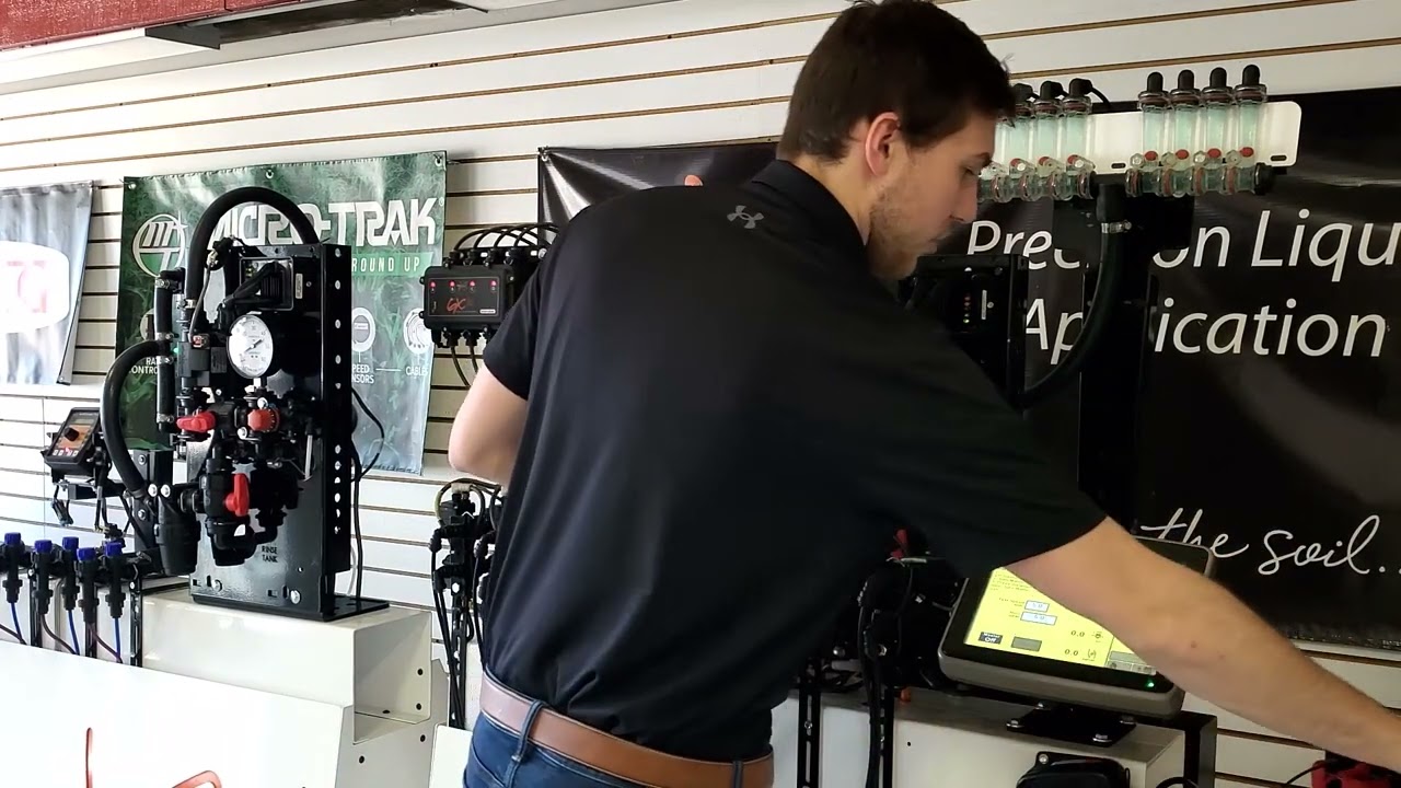
This practical video walks through how to test the voltage and signal output of an industrial flow meter — a foundational step in any diagnostic sequence that rules out electrical causes before investigating the meter itself.
Calibration, Certification, and Compliance
Accurate gas flow measurement is not only an operational requirement — it is a regulatory one for custody transfer, emissions reporting, and utility billing applications.
Key standards governing industrial gas metering:
| 標準 | Organization | Scope |
|---|---|---|
| AGA Report No. 3 | American Gas Association | Orifice metering of natural gas |
| AGA Report No. 7 | American Gas Association | Turbine metering of natural gas |
| AGA Report No. 9 | American Gas Association | Ultrasonic metering of natural gas |
| API MPMS Chapter 5 | American Petroleum Institute | Metering uncertainty for custody transfer (±0.25%) |
| OIML R137 | International Organization of Legal Metrology | Gas meters — metrological and technical requirements |
| ISO 17089 | International Organization for Standardization | Measurement of fluid flow in closed conduits — ultrasonic meters |
| EN 1359 | European Committee for Standardization | Diaphragm gas meters |
For projects serving both US and international clients, confirm which standard governs each measurement point. Mixing AGA and OIML reference conditions without explicit documentation is a common source of cross-border custody transfer disputes.
Calibration traceability means your calibration certificate references a measurement standard that is traceable — through an unbroken chain of comparisons with documented uncertainty — to a national or international standard. NIST (National Institute of Standards and Technology) is the US national metrology body; equivalent bodies include PTB (Germany), NPL (UK), and NIM (China). An A2LA-accredited laboratory (American Association for Laboratory Accreditation) provides the highest level of recognized calibration traceability for gas flow meters in North America.
Preventive Maintenance — Converting Reactive Troubleshooting into Proactive Performance Management
The economics of preventive maintenance are not subtle.
A thermal mass flow meter developing contamination-related sensor drift costs approximately $200–$400 to clean and verify during a planned maintenance window. Left until the drift becomes operationally visible, the remediation cost includes: unplanned process interruption ($1,500–$5,000 depending on the facility), expedited meter removal and inspection ($400–$800), rush recalibration ($600–$1,200), and — if the drift caused billing discrepancy — retrospective financial reconciliation.
Recommended preventive maintenance intervals:
| メーターの種類 | Functional Check | Cleaning / Inspection | Full Calibration Verification |
|---|---|---|---|
| Thermal mass flow | Every 3 months | Every 6 months | Annually |
| Turbine gas meter | Every 3–6 months | Every 6 months (contaminated gas) | Annually (custody), 2 years (utility) |
| Ultrasonic (inline) | Every 6 months | Annually or as needed | Annually |
| 渦流量計 | Every 6 months | Annually | Annually |
| コリオリ | Every 6 months | As needed (typically low) | Annually |
| ダイヤフラム | Every 12 months | Annually | Per regulatory schedule |
These intervals apply to standard clean-gas service. High-contamination applications — biogas, wet natural gas, compressor discharge — warrant intervals compressed by 50%.
Schedule maintenance around your operations, not your calendar. Align meter inspections with planned shutdown windows. A thermal mass flow meter that should be inspected in August but has a planned plant outage in September is better inspected in September during the shutdown — not forced into an unplanned service call in August because the calendar said so.
主要用語集
| Term | Definition |
|---|---|
| ACFM | Actual Cubic Feet per Minute — gas volume at actual operating temperature and pressure, not corrected to a reference condition |
| AGA | American Gas Association — industry organization that publishes widely adopted natural gas measurement standards |
| Calibration drift | The gradual deviation of a meter’s output from its true value over time, caused by wear, contamination, or environmental factors |
| Coriolis meter | A flow meter that measures mass flow directly by detecting the inertial effects of gas flowing through vibrating tubes |
| EMI | Electromagnetic Interference — electrical noise from motors, drives, or nearby power equipment that can corrupt flow meter signal outputs |
| Flow computer | An electronic device that calculates corrected or totalized flow from raw meter signals combined with pressure and temperature inputs |
| HART | Highway Addressable Remote Transducer — a communication protocol that overlays digital data on a standard 4–20 mA signal |
| K-factor | The calibration constant of a flow meter, expressed as pulses per unit volume, used to convert raw output to engineering units |
| Lock-Out/Tag-Out (LOTO) | Safety procedure requiring energy sources to be isolated and labeled before maintenance work begins |
| Nm³/h | Normal cubic meters per hour — gas volume corrected to standard conditions of 0°C and 1 atmosphere |
| OIML | International Organization of Legal Metrology — develops standards for measuring instruments used in regulated applications |
| Pulsation | Rapid, rhythmic pressure fluctuations in a gas line, typically caused by reciprocating compressors or rapid valve cycling |
| RTD | Resistance Temperature Detector — a temperature sensor whose electrical resistance changes predictably with temperature, used for flow compensation |
| SAT | Site Acceptance Test — a formal commissioning verification performed at the installation site before project handover |
| SCADA | Supervisory Control and Data Acquisition — a software platform that monitors, logs, and controls industrial process instruments |
| SCFM | Standard Cubic Feet per Minute — gas volume corrected to 60°F and 14.7 psia reference conditions |
| Thermal mass flow meter | A meter that measures gas mass flow by quantifying heat transfer between a heated sensing element and the flowing gas |
| Turndown ratio | The ratio of maximum to minimum measurable flow rate within the meter’s specified accuracy — a wider ratio means more measurement range |
| 渦流量計 | A meter that measures flow by counting the frequency of vortices shed from a bluff body obstruction in the gas stream |
The Jade Ant Instruments Technical Foundation
ジェイド・アント・インストゥルメンツ supplies gas flow meters — thermal mass, ultrasonic, turbine, vortex, and Coriolis — to OEM skid manufacturers, EPC contractors, instrument distributors, MRO teams, and municipal utilities across industrial markets worldwide.
Beyond the product catalog, the team provides application engineering support for meter selection, sizing, and installation review during the design phase — the highest-leverage point for preventing the field problems this guide documents. The gas flow meter troubleshooting resources at Jade Ant Instruments そして mass flow meter brands comparison guide are practical starting points for distributors and integrators building their technical competency in gas measurement.
よくある質問
1. How do I know if my gas meter is reading high or low?
The most reliable method is a side-by-side comparison with a calibrated reference meter. A portable clamp-on ultrasonic meter placed on the same pipe section provides a reference measurement without any process interruption. If a 2–3% difference or greater exists between the reference and the installed meter during stable, mid-range flow conditions, your installed meter has drifted out of specification. For custody transfer applications, a mobile proving unit provides a higher-accuracy reference.
2. What are the most common causes of gas meter inaccuracy in industrial facilities?
Field experience consistently identifies four primary causes: (1) improper installation — insufficient straight-run piping, incorrect orientation, or vibration-prone mounting; (2) wet gas or liquid carryover contaminating sensors; (3) calibration drift from bearing wear, sensor aging, or contamination; and (4) signal interference from ground loops, EMI, or poor cable shielding. Research from gas measurement field studies shows that errors exceeding 20% are documented in real installations from environmental and installation factors — not equipment failure.
3. Can temperature fluctuations affect gas flow readings?
Yes — significantly. Gas is compressible, so its volume changes with temperature. A meter measuring actual volumetric flow without temperature compensation will report higher volumes in warm conditions (gas is less dense) and lower volumes in cold conditions. For a gas line operating between 5°C and 35°C without temperature compensation, the measurement variation is approximately 10% — entirely attributable to temperature, with no change in actual mass throughput.
4. How often should gas meters be calibrated in industrial applications?
The answer depends on application criticality and operating environment. Custody transfer fiscal meters require calibration every 6–12 months per AGA and API MPMS requirements. Process control meters operating in clean, stable conditions can typically be calibrated every 1–2 years. High-contamination applications (biogas, wet gas, compressor discharge) should be calibrated annually regardless of technology. Any meter showing unexplained reading changes should be treated as requiring immediate calibration verification regardless of scheduled interval.
5. What is the minimum straight-run piping required for turbine gas meters?
For a single elbow upstream, turbine meters require a minimum of 10 pipe diameters of straight, unobstructed pipe upstream of the meter inlet and 5 pipe diameters downstream. For a double elbow out-of-plane — the worst-case upstream disturbance — the upstream requirement increases to 20 pipe diameters. These requirements cannot be substituted by recalibration; insufficient straight run produces systematic measurement error that calibration cannot correct.
6. Why is my ultrasonic meter showing zero flow when gas is clearly moving?
Three causes account for the majority of this fault pattern: (1) the actual flow rate is below the meter’s minimum detection threshold — ultrasonic transit-time meters (which measure flow by comparing acoustic pulse travel times upstream and downstream) have a low-flow cutoff below which signal differentiation becomes unreliable; (2) transducer face contamination has attenuated the acoustic signal to the point where the meter cannot establish a valid measurement; or (3) the meter’s signal processing has detected too much noise and defaulted to zero output as a fail-safe. Check the meter’s signal quality or SNR diagnostic parameter first.
7. Can vibration permanently damage a gas flow meter?
Yes. Turbine meters suffer bearing wear and rotor damage from sustained vibration, altering the rotor speed–flow relationship permanently. Vortex meters can experience piezoelectric sensor cracking from high-amplitude mechanical shock. Coriolis meters — while generally robust — can suffer tube fatigue in severe vibration environments with specific resonant frequencies. In all cases, use flexible pipe connections, vibration-absorbing mounting, and assess whether meter relocation away from vibration sources is feasible.
8. How do I verify the 4–20 mA output of my flow transmitter?
Connect a calibrated loop calibrator in series with the 4–20 mA output circuit. With the process at zero flow, the output should be exactly 4.00 mA (representing 0% of range). At full-scale flow, the output should be exactly 20.00 mA (100% of range). At any intermediate flow, the output should be linearly proportional. A discrepancy between the meter’s displayed flow and the corresponding 4–20 mA output indicates an output circuit fault — not a measurement fault — and should be investigated in the meter’s output electronics rather than the sensing element.
9. What should I do if my flow computer displays inconsistent readings?
Start with the inputs, not the flow computer. Verify each input independently: confirm the pressure transmitter reading against a reference gauge at the same tap; confirm the RTD reading against a reference thermometer at the same point; confirm the meter’s primary output (pulse or 4–20 mA) against a direct measurement. If all inputs are verified correct and the flow computer output is still incorrect, check the configuration — reference conditions, gas composition, K-factor, and engineering unit selections. Firmware version and configuration backup verification should follow if configuration appears correct.
10. Is it safe to bypass a gas meter during diagnostic work?
Only under strictly controlled conditions: proper upstream and downstream isolation, full depressurization and purging of the isolated section, a gas-free atmosphere verified by portable gas detector, and active Lock-Out/Tag-Out implemented on all isolation valves. For natural gas systems, additional requirements include hot-work permits for any work involving open flanges, and in many jurisdictions, a gas safety officer or authorized person must be present. Never bypass a gas meter on an active line without completing your full site-specific isolation procedure.
11. How do I detect a gas leak that might be affecting meter performance?
A gas leak upstream of the meter — particularly on the high-pressure side — can cause the meter to report lower flow than is actually entering the pipe section, because some gas is escaping before reaching the meter. Use a calibrated portable gas detector (combustible gas indicator) to survey all flanged connections, valve packings, and instrument impulse lines upstream and around the meter. An ultrasonic leak detector is effective for pressurized leaks that are too small to detect by smell but large enough to affect measurement integrity.
12. Can firmware updates cause measurement problems?
Yes — and this is more common than most teams expect. Firmware updates can reset configuration parameters, change the K-factor entry in the meter’s register, modify the low-flow cutoff threshold, alter the engineering unit conversion, or change the HART command set. Best practice is to export a full configuration backup before any firmware update, and to verify all critical parameters — K-factor, gas type, reference conditions, engineering units, output scaling — immediately after the update is applied. Some manufacturers require that meters be returned to the factory for firmware updates in custody transfer applications to maintain certification validity.
13. What documentation should I maintain for gas meter regulatory audits?
A complete and audit-ready gas meter documentation package includes: installation records (as-built drawings, piping configuration, installation date); calibration certificates for every calibration event with as-found and as-left data; maintenance logs for every inspection, cleaning, and repair; configuration backups with date and firmware version; and any deviation reports documenting instances where the meter operated outside its specified parameters. For custody transfer meters, this documentation must be readily accessible for inspection and retained for the period specified by the applicable regulatory authority — typically 3–7 years depending on jurisdiction.
14. How should I handle a dispute with a customer over gas consumption measurements?
Present your calibration history with traceable certificates showing the meter was within specification during the disputed period. Commission an independent third-party reference measurement by an accredited calibration laboratory — a clamp-on ultrasonic reference meter or mobile proving unit comparison conducted in the presence of both parties provides defensible, independent evidence. If the independent measurement confirms the installed meter’s accuracy, present the results formally in writing. If it identifies a discrepancy, pursue root cause analysis before agreeing to any billing adjustment, as the source of the error determines which party bears responsibility.
15. Are smart gas meters self-diagnosing? Can I trust their alerts?
Modern smart gas meters provide valuable diagnostic data — signal quality indices, sensor health flags, flow stability indicators, and communication error codes — that significantly improve early fault detection compared to conventional meters. However, they are not autonomous diagnostic systems. A “low signal quality” alert requires human interpretation to determine whether the cause is transducer fouling, liquid carryover, or external EMI. A “zero flow” alarm requires verification that actual flow has ceased, not just that the meter has lost measurement. Smart meter diagnostics narrow the field of investigation quickly — but field validation by a technician remains essential. Think of the alerts as your starting point, not your conclusion.
External references used in this guide:
- Sage Metering — True Cost of Inaccurate Gas Flow Measurement
- Power Engineering — Metering Matters: Inaccurate Gas Measurement Can Cost Thousands
- Industrial Monitor Direct — Flow Meter Straight Run Requirements
- Sierra Instruments — Most Common Flow Meter Problems and Solutions
- Kobold USA — Significance of Calibration in Flow Meters
- Flowell — How Often Should Industrial Flow Meters Be Serviced
- Process Vision — Liquid Carryover in Natural Gas Processing
- Jade Ant Instruments — Gas Flow Meter Troubleshooting Guide for Distributors
- Jade Ant Instruments — Custody Transfer Flow Meters: Compliance & ROI Guide
- Jade Ant Instruments — Flow Meter Selection Guide