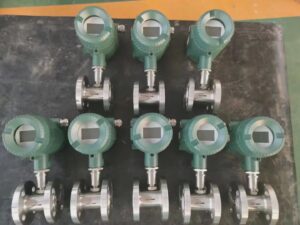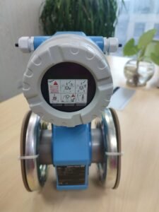
Your Complete Guide to Selecting the Right Flow Measurement Technology for Your Customer Applications
How to use this guide: Whether you’re responding to an RFQ, building a customer proposal, or training a new account manager, this decision framework gives you the technical grounding to stop guessing and start recommending with confidence. Work through each section sequentially the first time. After that, treat it as a reference: jump to the application type or objection that’s relevant to your next customer conversation.

Why Your Customers Are Asking the Wrong Questions About Flow Measurement
The Real Cost of Recommending the Wrong Technology
Here’s a scenario that plays out in distributor sales teams more often than anyone admits: a procurement manager at a food processing plant asks for “a flow meter for our compressed air lines.” The rep pulls up the catalog, quotes a standard turbine meter — it’s familiar, it’s in stock, the margin is reasonable. The installation goes in. Six months later, the plant’s energy team runs an audit and discovers the meter is reading 12% low at typical operating conditions because no one accounted for the pressure and temperature swings between the compressor room and the point of use.
That 12% error isn’t a product defect. It’s a technology selection error. And your customer’s maintenance manager is now on the phone asking why you sold them something that doesn’t work.
The financial consequences compound quickly. In a manufacturing facility consuming 1,500 Nm³/h of compressed air, a 12% measurement error means 180 Nm³/h of untracked flow. At typical industrial compressed air costs of $0.025–$0.04 per Nm³, that’s $4,500–$7,200 per month in unaccounted energy — invisible until someone runs the numbers. The root cause: recommending a volumetric meter for a compressible gas application where mass measurement was the right answer.
Your reputation in your customer’s organization is built on the quality of your recommendations. A wrong technology recommendation doesn’t just cost the customer money — it costs you the next three purchase orders and the referral you were counting on.
What Your Customers Actually Need (But Don’t Know How to Ask For)
Most industrial buyers describe their flow measurement need in terms of what they already have, not what they actually need. “We need a flow meter for natural gas” typically means one of several entirely different things: custody transfer billing, combustion control feedback, leak detection, or energy metering for cost allocation. Each requirement maps to a different technology with different accuracy, maintenance, and installation implications.
The distributor who asks the next three questions — “What decision will this measurement drive?”, “What happens when the temperature or pressure changes?”, and “What does a 1% error cost you in this application?” — is the one who earns the reputation of trusted advisor. The one who just quotes from the catalog is the one who gets replaced when a more knowledgeable competitor shows up.
The gap between what customers ask for and what they actually need is your opportunity. Closing that gap is exactly what this guide is built to help you do.
The Complete Comparison Matrix: Thermal Mass vs. Volumetric vs. Differential Pressure
Structure 1 — Measurement Principle: How Each Technology Actually Works
Thermal mass flow meters: Direct mass measurement through heat transfer
A thermal mass flow meter measures gas flow by quantifying how much heat is carried away from a heated sensor element by the moving gas stream. The physics is straightforward: the faster gas moves past the sensor, the more heat it carries away, and the more electrical power is required to maintain the sensor at its setpoint temperature. That power demand is the measurement signal, and it corresponds directly to mass flow — not volumetric flow.
The critical word here is mass. The meter counts molecules, not volume. At 8 bar of pressure, there are eight times as many air molecules in a given pipe cross-section as there are at 1 bar. A volumetric meter would report the same “flow” regardless. A thermal mass meter reports the actual mass moving through — which is what your customers’ processes actually consume.
Volumetric flow meters: Volume-based measurement and its hidden limitations
Turbine meters, vortex meters, and positive displacement meters all count volume: the number of cubic meters of fluid that pass a point per unit time. For incompressible liquids — water, oil, most chemicals — this works well because density is essentially constant. A cubic meter of water at 15°C and a cubic meter at 60°C contain nearly the same mass.
For gases, this assumption collapses. A cubic meter of compressed air at 7 bar and 25°C contains roughly 8× more mass than a cubic meter at ambient pressure. If pressure fluctuates by ±10% during normal system operation — which is routine in most industrial compressed air systems — a volumetric meter’s reading fluctuates with it, even if the actual mass consumption hasn’t changed. The meter is technically working correctly. It’s just answering the wrong question.
Differential pressure (DP) meters: Why this legacy technology still dominates (and when it shouldn’t)
Differential pressure meters — orifice plates being the most common — work by creating a constriction in the pipe and measuring the pressure drop across it. Flow rate is calculated from the pressure differential using Bernoulli’s principle. The technology is 100+ years old, universally understood, and found in virtually every industrial facility on the planet.
DP meters persist because they’re simple to understand, easy to maintain independently, and accepted by nearly every regulatory framework for custody transfer. Orifice plates can be replaced with a wrench. The transmitters are standard. The engineering is documented in ASME and ISO standards going back decades.
What DP meters are not: accurate across a wide flow range, maintenance-free, or well-suited to modern facilities with dynamic gas measurement requirements. The performance story — which we’ll cover next — is significantly worse than most customers realize.
Structure 2 — Accuracy Performance Across Real-World Conditions
Thermal mass accuracy in compressible gases
Under properly specified conditions, thermal mass flow meters achieve accuracy of ±1% of reading plus ±0.5% of full scale, with premium instruments from leading manufacturers reaching ±0.5% of reading. More practically important than the headline number: this accuracy is maintained across the full operating range, including at low-flow conditions where other technologies degrade severely.
The turndown ratio — the ratio of maximum to minimum measurable flow — is one of the most underappreciated performance specifications in flow measurement. Thermal mass meters routinely achieve 100:1 turndown. This means a meter sized for 1,000 Nm³/h remains accurate down to 10 Nm³/h. For compressed air monitoring in a manufacturing facility where demand swings from full production to weekend standby, this range matters enormously. The single thermal mass meter covers the full operating envelope without a separate low-flow instrument.
Volumetric accuracy degradation with temperature and pressure changes
A turbine meter specified at ±0.5% accuracy delivers that accuracy at the conditions it was calibrated for: a specific fluid, specific temperature, specific pressure, and specific viscosity. Move any of those conditions and the accuracy degrades — sometimes significantly.
In a natural gas application with ±5% pressure variation and ±20°C temperature swing over a day (both realistic in industrial settings), uncorrected volumetric measurement error can easily reach ±3–5%. Some customers add external pressure and temperature transmitters with a flow computer to apply real-time correction. This adds cost, adds components that can fail, and still depends on accurate sensor readings from those additional instruments. The fundamental limitation is that volumetric measurement wasn’t designed for the variable conditions of real gas applications.
DP meter accuracy: Why it’s worse than your customers think
Orifice plates are commonly specified at ±0.5–1.0% of rate at nominal flow conditions. What this specification obscures is the square-root relationship between differential pressure and flow rate. At 50% of rated flow, the DP signal is only 25% of full scale — the meter is operating in its least accurate region. At 10% of rated flow, the DP signal is 1% of full scale, which is below the practical resolution of most transmitters.
Practical turndown for orifice plates is approximately 3:1 to 5:1 before accuracy deteriorates to unacceptable levels. For applications with variable demand — which is most applications — this is a severe limitation. Many DP meter installations compensate by installing multiple sized orifice plates or by accepting large inaccuracies at off-design flow rates. Neither is a satisfying solution.
Structure 3 — Installation and Maintenance: The Hidden Cost Factor
Thermal mass: Minimal invasiveness, maximum uptime
Thermal mass meters require 10–20 pipe diameters of straight, unobstructed pipe upstream of the sensor location, and 5 pipe diameters downstream. This is meaningfully less demanding than other technologies in most applications. The sensor element itself occupies a small portion of the pipe cross-section for insertion-type designs, creating negligible pressure drop — typically less than 0.1 kPa even at full flow.
Insertion-type thermal mass meters can often be installed in existing pipe through hot-tap fittings without shutting down the process, which is a significant advantage for retrofit applications. There are no impulse lines, no remote seals, no condensate traps, and no moving parts that wear. A well-installed thermal mass meter in a clean gas application can operate for 5–10 years without any maintenance beyond an annual inspection.
Volumetric meters: Straight-run requirements that complicate piping
Turbine meters typically require 10–15 pipe diameters upstream and 5 downstream of unobstructed straight pipe. Vortex meters require 15–20 upstream in many configurations. In crowded industrial facilities — which is most industrial facilities — finding this straight run often requires piping modifications that add material cost, labor cost, and project timeline.
Turbine meters contain rotating mechanical elements that wear over time. In gas applications, bearing wear from particulates or condensate is a leading cause of field failures. Calibration drift develops gradually as bearings wear, which means the meter may be significantly off before anyone notices.
DP meters: The installation nightmare that kills your customer’s project timeline
An orifice plate installation involves the primary element (the plate itself), two pressure taps in the pipe wall, impulse lines running from those taps to the differential pressure transmitter, impulse line valving (block and bleed arrangements), and often a flow computer to convert the DP signal to flow rate. Each of these connections is a potential leak path. In gas service, leak detection and ongoing integrity checks are required.
Impulse lines in gas service must be sloped to drain condensate, or heated with heat tracing if the gas can condense. In outdoor installations or in applications where the gas temperature is close to its dew point, impulse line management becomes a maintenance activity in its own right. Icing in cold climates, condensate blockages, and connection leaks are the leading causes of DP meter measurement errors in field service — none of them related to the measurement principle itself, all of them preventable with better technology choices.
Structure 4 — Capital and Lifetime Operating Costs
Why thermal mass initial cost is often lower than customers expect
A complete thermal mass meter installation — meter, transmitter, cable, and commissioning — typically costs $2,000–$6,000 for a 2-inch to 6-inch pipe in a standard compressed air or natural gas application. This surprises customers who have heard that thermal mass is “expensive.” The comparison point matters: compared to an orifice plate element alone, thermal mass is more expensive. Compared to a complete, functioning, calibrated DP installation with impulse lines, valving, transmitter, and flow computer — thermal mass is competitive or cheaper, installed.
Volumetric meter total cost of ownership: Accounting for calibration and drift
Turbine meters in gas service typically require annual calibration. The calibration cost itself is modest, but removing the meter from service, shipping it to a calibration lab, reinstalling it, and dealing with whatever process disruption occurs during the maintenance window adds up. Over a 10-year installed life, a turbine meter in an industrial gas application accumulates calibration costs of $3,000–$6,000 and faces one or two bearing replacement events at $800–$1,500 each.
DP meter costs: Orifice plates, impulse lines, and the maintenance trap
The orifice plate itself is inexpensive — $150–$500 for a standard plate. Everything else is not. A complete DP installation with proper impulse line configuration, stainless manifold valving, smart DP transmitter, and flow computer runs $4,000–$10,000 in typical industrial service. Ongoing costs include annual impulse line inspection and flushing, orifice bore inspection (plates wear over time from gas velocity, particularly if any particulates are present), and the labor associated with three or four separate components that all require calibration documentation.
A realistic 10-year TCO comparison for a 4-inch gas flow metering point:
| Cost Element | Masse thermique | Turbine (Volumetric) | Orifice Plate (DP) |
|---|---|---|---|
| Initial purchase + installation | $3,500 | $2,800 | $7,200 |
| Annual maintenance labor (10 yr) | $2,000 | $4,500 | $8,000 |
| Calibration costs (10 yr) | $1,500 | $4,000 | $3,500 |
| Unplanned repairs / replacement | $500 | $2,200 | $3,800 |
| Energy penalty (pressure drop) | Négligeable | Négligeable | $2,400 |
| 10-Year Total | $7,500 | $13,500 | $24,900 |
Figures are representative estimates based on typical industrial installations. Actual costs vary by application, labor rates, and specific installation conditions.
When Thermal Mass Flow Meters Win: Application-Specific Decision Framework
Structure 5 — Gas Applications Where Thermal Mass Dominates
Compressed air systems: Eliminating your customer’s energy waste
Compressed air is one of the most expensive utilities in industrial manufacturing — typically costing $0.025–$0.04 per Nm³ when you account for compressor energy, maintenance, and drying. Most facilities have almost no accurate measurement of where that compressed air actually goes, which means most facilities also have no idea where it’s being wasted.
The typical compressed air system in a mid-size manufacturing facility has 20–30% leakage by volume. This is an industry-documented reality, not an exception. A factory running 10 compressors to support actual production demand of 7 compressors is running 3 compressors to maintain pressure in a leaking system. At $80,000–$120,000/year per compressor in energy costs, the unmetered leak loss is material.
Installing thermal mass meters at the mains and at branch feeds to production lines gives the energy manager the data to find and fix leaks, allocate costs to production departments, and demonstrate payback on efficiency projects. This is not a theoretical benefit — it’s the documented outcome of practically every serious compressed air audit performed with accurate flow data. The 18% energy saving mentioned throughout this industry context isn’t an outlier; it’s consistent with what facilities achieve when they measure compressed air properly for the first time.
Natural gas measurement: Meeting requirements without DP complexity
Natural gas custody transfer and process measurement requirements are well-served by thermal mass technology in all but the most regulated fiscal metering applications. A packaging line’s natural gas to burners, a boiler plant’s fuel consumption monitoring, a co-generation facility’s fuel accounting — all are appropriate thermal mass applications. Accuracy of ±1% of reading is sufficient for these applications, and the zero-maintenance profile of a thermal mass meter versus the ongoing impulse line care of a DP installation is a convincing operational advantage.
Biogas and renewable gas applications: Variable composition, stable measurement
Biogas from anaerobic digesters contains variable ratios of methane (typically 55–70%) and CO₂ (30–45%), with traces of hydrogen sulfide and water vapor. The composition changes with feedstock, temperature, and biological activity. A volumetric meter measuring biogas cannot tell you how much energy content is flowing — the same volumetric flow at 60% methane contains significantly more energy than at 55% methane.
A thermal mass meter, calibrated for the expected gas composition range, measures mass flow directly and provides a stable, composition-independent mass reading. When combined with a gas composition analyzer, you have the most accurate energy content measurement available. For a landfill gas-to-energy project or a food waste digester, this accuracy directly affects revenue from energy sales.
Structure 6 — The Compressible Gas Advantage: Your Most Powerful Selling Point
Direct mass measurement: Why this matters for your customer’s energy costs
The fundamental advantage of thermal mass measurement in gas applications can be illustrated with a number your customers can verify: compressed air at 7 bar pressure contains 8× the mass of air per cubic meter compared to air at atmospheric pressure. If your customer’s compressed air pressure varies between 6.5 and 7.5 bar across a production day — a ±7% swing that’s completely normal — a volumetric meter reading swings by ±7% with it, even if actual consumption hasn’t changed.
For a plant energy manager trying to understand compressed air consumption trends, ±7% baseline noise from the measurement system makes meaningful analysis impossible. With thermal mass, the same pressure fluctuation is invisible — the meter counts mass, which is what the compressor actually had to generate, regardless of what the downstream pressure happened to be at that moment.
Temperature and pressure compensation: Built-in, not bolted-on
Thermal mass meters provide mass flow measurement directly from the physics of heat transfer. They don’t require external pressure transmitters, temperature transmitters, or a flow computer to apply AGA-7 or similar gas corrections. The compensation is inherent in the measurement principle, not applied after the fact by a calculation that introduces its own uncertainty.
This matters in two practical ways: first, there’s less installed equipment to maintain and calibrate; second, the measurement accuracy doesn’t depend on the pressure and temperature transmitters being correctly calibrated. Every additional instrument in a measurement chain introduces additional uncertainty. Thermal mass eliminates two of those instruments in gas applications.
When Your Customers Should Choose Volumetric Meters Instead
Structure 7 — Liquid Applications and Why Volumetric Still Reigns
Water flow measurement: Where volumetric technology is adequate and cost-effective
For clean water at stable temperatures — municipal distribution, cooling tower makeup, irrigation systems, process water supply — electromagnetic flow meters and turbine meters provide excellent accuracy at lower cost than thermal mass. Water density varies by only 2% between 0°C and 50°C, so the volume-to-mass approximation holds well. The measurement principle mismatch that makes volumetric unsuitable for compressible gases simply doesn’t apply to incompressible liquids.
This is an important point for your customer conversations: recommending thermal mass technology for liquid applications is not only unnecessary — it’s often technically suboptimal. Electromagnetic flow meters measure conductive liquid volumetrically with ±0.3–0.5% accuracy and no moving parts. For most liquid applications, they’re the better answer. Part of building credibility as a trusted advisor is recommending the right technology for each application, not advocating for one technology across all situations.
Hydrocarbon liquids: When density is stable and thermal mass is overkill
Crude oil, refined petroleum products, and most hydrocarbon liquids have density that can be reliably predicted from temperature. A positive displacement or Coriolis meter with temperature correction provides the accuracy required for custody transfer at substantially lower cost than thermal mass. The industry’s custody transfer standards (API MPMS Chapter 5) are built around volumetric meters with temperature correction for a reason — it works accurately enough for financial transactions.
Low-viscosity applications: Reducing customer concerns
Low-viscosity fluids (below approximately 10 cSt) flow predictably through turbine and vortex meters without the bearing wear issues that affect higher-viscosity products. For clean, stable liquids in this viscosity range, volumetric meters deliver good accuracy, long service life, and lower cost. Recommending thermal mass technology here would be technically defensible but economically unjustifiable.
Structure 8 — High-Flow, Low-Pressure Scenarios
In large-diameter duct applications — ventilation monitoring, stack flow measurement, large combustion air systems — insertion thermal mass meters are available, but so are pitot tubes and annubar differential pressure devices that may offer simpler installation in non-critical measurement applications. When your customer needs ±5% accuracy for regulatory reporting on a 36-inch duct and is primarily concerned with cost, there are DP solutions that are adequate at lower capital cost.
The decision framework here is straightforward: if accuracy requirements are ±2% or better, or if the measurement will drive energy billing or process control, thermal mass wins. If accuracy requirements are ±5–10% and the measurement is primarily for regulatory compliance documentation (not optimization), the simpler and cheaper solution may be acceptable. Be honest with your customer about where the value justification exists and where it doesn’t.
When Differential Pressure Meters Are Your Only Option (And Why This Is Changing)
Structure 9 — Legacy System Integration and Regulatory Constraints
Custody transfer applications: Where DP meters are still mandated
In natural gas custody transfer — where the measurement directly determines a financial transaction between buyer and seller — regulatory acceptance is not optional. In many jurisdictions, fiscal metering for natural gas must use technologies approved under AGA-7 (turbine), AGA-9 (ultrasonic), or AGA-3 (orifice plate) standards. Thermal mass flow meters, despite their technical merit, are not currently approved under AGA-3 for custody transfer billing in most regulatory frameworks.
If your customer asks for a flow meter for a gas custody transfer point — a utility metering station, a pipeline interconnect, a gas distribution offtake — advise them correctly: this is a regulatory decision, not a technical one, and the approved technology list is defined by their regulatory authority, not by what works best technically.
Existing infrastructure: When replacement cost justifies keeping DP technology
A facility with 200 DP meter installations across multiple production lines has made an enormous investment in impulse lines, manifolds, transmitters, and flow computers — all of which are calibrated, documented, and integrated into their control system. Recommending a complete upgrade to thermal mass technology requires a payback analysis that may or may not support the investment depending on the specific application mix.
The correct approach: identify the subset of applications where thermal mass provides the clearest operational advantage (compressed air monitoring, gas leak detection, variable-demand gas applications), calculate the specific ROI for those applications, and present a phased upgrade strategy. Starting with the highest-value applications first builds the business case for subsequent phases.
Structure 10 — The Economics of Upgrading From DP to Thermal Mass
When the payback period justifies replacement
The payback calculation for replacing a DP installation with thermal mass requires four inputs from your customer: current annual maintenance cost for the DP installation (labor + materials), the cost of measurement inaccuracy at low flows (the percentage of operating time below the DP meter’s accurate range, multiplied by the cost of that error), any energy savings from eliminating the DP pressure drop, and the installed cost of the thermal mass replacement.
For a compressed air monitoring application currently using an orifice plate, with $800/year in impulse line maintenance, 30% of operating time in the low-flow accuracy degradation zone, and a $120/year impulse line energy penalty, the total annual benefit of switching to thermal mass is realistically $1,500–$2,500/year. Against a thermal mass installation cost of $3,500–$5,000, the simple payback is 2–3 years — a compelling business case for most industrial customers.
Your Interactive Decision Matrix: A Tool Your Sales Team Can Use Today
Quick-Reference Comparison Table
| Application | Fluid | Temperature | Pressure | Recommended Technology | Second Choice | À éviter |
|---|---|---|---|---|---|---|
| Compressed air monitoring | Gas | Ambient | 6–10 bar | Masse thermique | Vortex | Turbine, Orifice |
| Natural gas (process) | Gas | Ambient–250°C | Variable | Masse thermique | Vortex | Orifice (high maintenance) |
| Natural gas (custody transfer) | Gas | Ambient | Stable | Ultrasonic / Turbine (AGA) | Orifice (AGA-3) | Thermal Mass (not AGA approved) |
| Biogas / landfill gas | Gas | Ambient | Near-atm | Masse thermique | Vortex | Turbine (bearing wear, H₂S) |
| Hydrogen fuel | Gas | Ambient | Variable | Masse thermique | Coriolis | Turbine, Orifice |
| Clean water | Liquid | 0–80°C | Any | Électromagnétique | Turbine | Thermal Mass (overkill) |
| Process chemicals (conductive) | Liquid | Any | Any | Électromagnétique | Coriolis | DP (corrosion risk) |
| Hydrocarbons (liquid) | Liquid | Stable | Any | Turbine / PD | Coriolis | Masse thermique |
| Steam (saturated) | Gas | 100–250°C | Variable | Vortex | DP (orifice) | Masse thermique |
| Fuel gas (burner control) | Gas | Ambient | Faible | Masse thermique | Coriolis | Orifice |
| Corrosive gas | Gas | Ambient | Low–Med | Masse thermique (SS/Hastelloy) | Coriolis | Turbine (bearing attack) |
| Low-flow gas (instrument air) | Gas | Ambient | Faible | Masse thermique (calorimetric) | Rotameter | Orifice (too insensitive) |
Application-Specific Recommendation Flowchart
Step 1 — Identify fluid phase: Is the fluid a gas, a liquid, or steam? If steam, go to vortex or DP first. If liquid, go to electromagnetic or Coriolis first. If gas, continue to Step 2.
Step 2 — Is custody transfer or fiscal metering required? If yes, check your regulatory authority’s approved technology list. If the answer is orifice plate or turbine for AGA reasons, that decision is made. If no, continue.
Step 3 — Is the gas composition variable? If yes (biogas, landfill gas, mixed process gas, hydrogen blends), thermal mass is the preferred technology because it measures mass directly, independent of composition changes that would shift volumetric meter K-factors.
Step 4 — What is the flow turndown requirement? If demand ranges more than 10:1 between peak and minimum (common in manufacturing compressed air, batch gas applications), thermal mass 100:1 turndown is decisive. Orifice plates at 3:1–5:1 and turbines at 10:1 are inadequate for variable-demand applications.
Step 5 — What is the installation environment? If the piping is congested (limited straight run), if the customer needs hot-tap installation without a process shutdown, or if the environment is corrosive, thermal mass with appropriate material selection is the preferred answer.

Overcoming Customer Objections: The Responses Your Sales Team Needs
“Thermal Mass Flow Meters Are Too Expensive”
How to reframe the conversation around total cost of ownership
When a customer says “too expensive,” they’re comparing your unit price against a number they’ve seen on a competitor’s quote or a catalog page. That comparison is almost never apples-to-apples. Walk them through a specific TCO calculation using their numbers: their current maintenance cost for whatever they’re replacing, the cost of calibration cycles they’re currently managing, and — in gas applications — the quantified value of improved accuracy at low-flow conditions.
A common calculation for a compressed air monitoring replacement: customer currently has an orifice plate installation costing $900/year in maintenance, with known measurement errors at shift-change demand levels. Thermal mass installation is $1,200 more than the orifice plate replacement they were considering. Payback: 16 months. Over a 10-year installed life, the net present value of switching to thermal mass is positive by $6,000–$8,000 versus the DP option. Present this math; don’t argue about the list price.
Competitive pricing strategies when customers compare quotes
If a customer has a competing thermal mass quote that’s 15–20% lower in unit cost, the conversation needs to focus on two things: specifications and support. What’s the accuracy at 10% of rated flow on the competitor’s meter? What’s the calibration interval? What material are the wetted sensors made of, and what’s the supplier’s track record in your customer’s specific gas application? Price convergence at the specification level usually reveals that the cheaper option has compromises — narrower range, lower accuracy at low flow, or shorter sensor life in the presence of contamination.
“We’ve Always Used Volumetric Meters — Why Change?”
The risk of staying with outdated technology
This objection is really about risk aversion, not about volumetric meters being technically superior. Acknowledge that directly: “You’ve made volumetric meters work, and I’m not saying they’ve failed. Here’s what you might be leaving on the table.” Then make it specific: show them a calculation of what a ±7% baseline measurement error costs them in untracked compressed air consumption. Show them the maintenance log cost for their turbine meter bearings over the last 3 years. Make the status quo have a cost, because it does — it’s just invisible because no one has calculated it.
How to position thermal mass as a competitive advantage
In industries where energy cost allocation, sustainability reporting, and ISO 50001 energy management certification are becoming standard practice, accurate compressed air and gas flow data is an operational necessity, not an optional upgrade. A customer who installs thermal mass metering across their facility has the data infrastructure for ISO 50001, for internal cost allocation, and for identifying and eliminating compressed air leaks. That’s a business capability they didn’t have before — not just a meter swap.
“Our Application Is Too Dirty for Thermal Mass”
Why this objection is based on outdated information
Early thermal mass meters — particularly the delicate hot-wire sensors from the 1980s and early 1990s — were legitimately sensitive to contaminated gas streams. The technology has changed substantially. Modern insertion-type thermal mass meters for industrial gas applications use robust platinum RTD sensors encased in stainless steel sheaths, with sensor diameters large enough to resist mechanical damage and surface finishes designed to resist fouling. Self-diagnostic functions in current-generation electronics can detect sensor contamination and flag calibration drift before measurement accuracy is compromised.
Protective measures for harsh environments
For gas streams with particulate content, separator filters upstream of the meter are standard practice and add minimal cost and pressure drop. For corrosive gas applications — H₂S-bearing biogas, chlorinated process gases, acid gas handling — Hastelloy C-276 or Inconel sensor construction is available from manufacturers including Jade Ant Instruments’ thermal flow meter line. The question isn’t “can thermal mass handle this?” — it’s “what construction specification is required for this gas?”
“We Need DP Meters Because of Regulatory Requirements”
Understanding which regulations actually mandate DP technology
This objection is correct in one specific context: fiscal gas metering under AGA-3 (orifice plates). In most other contexts, it’s either incorrect or overstated. Environmental emissions monitoring under EPA Method 2F and similar standards has accepted thermal mass meters for stack flow measurement. Many state and local utility metering codes accept thermal mass for sub-metering and process metering, while only requiring orifice plate or ultrasonic measurement for utility custody transfer points.
Help your customer distinguish between “we need DP meters” (possibly true for specific fiscal metering points) and “we need DP meters everywhere” (almost certainly not true for the majority of their gas measurement applications). Even a facility with a regulatory mandate at their gas inlet meter can use thermal mass technology throughout the facility for all internal metering.
Industry-Specific Guidance: Tailored Recommendations for Your Customer Base
Compressed Air Systems
Why thermal mass is the gold standard
An auto parts manufacturer running three production shifts installs thermal mass meters at the header of each production zone. Within three months of having the data, their energy team identifies one zone consuming 40% more compressed air per part produced than the other two. Investigation reveals a leaking pneumatic cylinder that maintenance had written off as a minor issue. The repair costs $80 in parts and takes two hours. The annual energy saving from fixing that one leak: $14,000. The meter that identified the leak: $3,800 installed.
This is the thermal mass value proposition for compressed air — not abstract accuracy numbers, but the ability to make decisions that weren’t possible without good data. When you propose thermal mass for compressed air, you’re proposing an energy management capability, not just a measurement device.
Energy auditing as a customer conversion tool
If your customer is skeptical, offer to help them conduct a compressed air audit using temporary thermal mass measurement. Borrow or rent two or three insertion meters, install them at key measurement points for 30 days, and analyze the data together. The audit almost always reveals 15–30% of compressed air consumption that was previously untracked. That finding is more compelling than any product brochure, and it naturally leads to a permanent metering project.
Natural Gas Distribution and Measurement
Custody transfer considerations
For natural gas distributor metering — where a commercial customer’s billing is determined by meter — consult your local utility’s approved meter list and regulatory requirements before proposing thermal mass. In many cases, the utility will specify the metering technology at the billing point. For all downstream measurement (sub-metering for cost allocation, burner control feedback, boiler monitoring), thermal mass is excellent.
Regulatory landscape and approval processes
Thermal mass meters have received approval for use in specific natural gas applications in multiple regulatory frameworks. In Europe, some EN 12480-compliant applications accept thermal mass. In the US, industrial process monitoring (as distinct from fiscal custody transfer) has broad acceptance. Work with your customer’s engineering team and local regulatory contacts to understand which applications require AGA-approved technology and which do not.
CVC et automatisation des bâtiments
Constant temperature thermal anemometer designs are the standard for HVAC duct flow measurement. They handle the wide flow range required by variable air volume (VAV) systems — from full cooling load to minimum ventilation — with a single instrument. Integration with building management systems via BACnet or Modbus is standard on modern instruments, making them compatible with all major BMS platforms.
For energy metering in district heating systems or chilled water distribution, however, electromagnetic flow meters paired with temperature sensors are the standard approach. Thermal mass is not the answer for liquid heat metering.
Transformation des produits alimentaires et des boissons
Hygiene and sanitary design requirements
In food processing applications involving direct gas contact with product — CO₂ for carbonation, N₂ for blanketing, compressed air for pneumatic conveying of food ingredients — the sensor materials and construction of the thermal mass meter must comply with applicable FDA and EHEDG standards. Specified construction includes 316L stainless steel sensors, electropolished surfaces, and sanitary process connections.
For compressed air monitoring in food facilities (plant utility, not product contact), standard industrial construction is appropriate. The critical specification question is: “Will this gas contact the product at any point?” If yes, food-grade specification is required. If no, standard industrial specification is adequate.
Ingredient metering and batch control applications
Nitrogen blanketing in wine tanks, CO₂ addition to carbonated beverages, and compressed gas for dough mixing all benefit from thermal mass accuracy at low flow rates. In a 5,000-liter wine tank blanketing application where nitrogen flow rates range from 2 Nm³/h (maintenance blanketing) to 20 Nm³/h (active purging), thermal mass provides stable accurate measurement across that 10:1 range where a DP meter would be unreliable at the low end.
Pharmaceutical and Chemical Manufacturing
Accuracy requirements for quality control
In pharmaceutical manufacturing, gas flow accuracy affects product quality directly: too little nitrogen blanketing allows oxidation; too much compressed air pressure variation affects capsule fill weights. A measured deviation from a validated process gas flow rate is a potential batch quality event. The repeatability specification of a thermal mass meter — typically ±0.25–0.5% of reading — is what the quality team needs for process validation documentation, not just operational monitoring.
Corrosive gas handling and material selection
Chlorine, HCl, SOₓ, and other corrosive process gases require sensor construction in corrosion-resistant alloys. Hastelloy C-276 is the standard for strongly oxidizing acids. Monel 400 works well for hydrofluoric acid applications. PVDF-coated sensors handle some chlorinated compounds. The selection of wetted materials is application-specific, and a correct material specification is worth more to your pharmaceutical customer than a competitive unit price.
Oil and Gas Operations
Custody transfer and fiscal metering requirements
As noted in the DP discussion, AGA and API standards govern custody transfer metering in oil and gas. For fiscal points, advise customers to follow their regulatory mandate. For all non-fiscal metering — flare gas monitoring, fuel gas to compressor drivers, vent gas monitoring, produced water gas content — thermal mass is an excellent choice with no regulatory conflict. Flare gas in particular benefits from thermal mass technology because flare flow rates span an enormous range, from pilot flame to emergency relief event, that no DP meter can handle in a single instrument.
Emissions monitoring integration
EPA 40 CFR Part 75 (air emissions monitoring for power plants) and similar regulations require accurate flow measurement for combustion stack emissions calculations. Thermal mass meters are accepted in multiple EPA Method alternatives for specific stack flow measurement applications. For flare gas to emissions reporting, thermal mass’s accuracy across the full flow range — including the low-flow idle conditions that represent most operating hours — is a significant advantage over alternatives.
Power Generation and Utilities
Fuel gas measurement and combustion control
Gas turbine fuel control systems require flow measurement with response times fast enough to follow the turbine’s load-following dynamics. Thermal mass meters with response times under 1 second are appropriate for control feedback. For boiler systems where response time is less critical, thermal mass provides accurate BTU-basis fuel accounting that supports both combustion optimization and environmental reporting.
Emissions monitoring integration
Carbon capture and storage (CCS) applications involve CO₂-rich gas streams that may also carry entrained moisture and trace contaminants. Thermal mass meters calibrated for CO₂-dominant gas compositions provide direct mass flow measurement essential for carbon accounting. This is an emerging application where thermal mass technology is being specified for new projects at an increasing rate, driven by regulatory carbon accounting requirements.
Technical Specifications You Need to Know
Accuracy and Repeatability Standards
When a thermal mass meter data sheet states ±1% of reading, this means the measurement error at any point in the flow range is within 1% of the actual flow at that point. Contrast this with ±1% of full scale, which means the error is within 1% of the maximum rated flow — which translates to a much larger percentage error at low flows. A meter rated at ±1% full scale, measuring at 10% of its range, has an accuracy of ±10% of reading at that condition. Always ask: “Is this specification expressed as percentage of reading or percentage of full scale?” The difference is significant.
Temperature and Pressure Compensation
Thermal mass meters measure mass directly through heat transfer physics. The measurement is inherently compensated for process gas temperature variation within the specified operating range. For pressure compensation, the thermal mass principle is also inherently insensitive to pressure changes (unlike volumetric meters), but for the highest accuracy applications, multipoint calibration at operating pressure is recommended. This is standard practice for manufacturers including Jade Ant Instruments, where calibration at application-specific conditions is available as a configuration option.
Response Time and Rangeability
Thermal mass meters typically achieve a response time (T90 — time to reach 90% of final value after a step change) of 1–3 seconds for standard industrial designs, with fast-response configurations reaching under 1 second. This is adequate for most process control feedback applications. For combustion control systems requiring faster response, verify the specific instrument’s T90 specification against the control system’s tuning requirements.
Rangeability (turndown ratio) is 100:1 for most industrial thermal mass meters, and up to 200:1 for premium designs. This single specification eliminates the need for multiple parallel meters to cover a wide flow range in compressed air or gas applications — a simplification that your customers will appreciate in system design.
Material and Coating Options
Standard sensor construction for industrial gas applications is 316/316L stainless steel, suitable for most air, nitrogen, CO₂, natural gas, and non-corrosive process gas applications. For applications involving H₂S, Cl₂, HCl, or other corrosive components, specify Hastelloy C-276 sensors. For food and pharmaceutical applications, specify electropolished 316L with sanitary process connections. Protective coatings — Parylene, PTFE, or Halar — are available for applications where neither stainless nor exotic alloys are optimal.

Implementation Strategy: How to Position Yourself as the Expert Your Customers Trust
Building Your Technical Knowledge Base
The distributors who dominate in flow measurement aren’t necessarily the ones with the lowest prices or the fastest delivery. They’re the ones who can answer the questions that the other three vendors couldn’t. Building that knowledge base requires deliberate investment.
For your sales team, the minimum foundation includes understanding the difference between mass and volumetric measurement (which this guide addresses), knowing the key specifications to ask about and what they mean in practice (accuracy expression, turndown ratio, response time, material compatibility), and being able to sketch a TCO comparison that uses customer-specific numbers. That’s enough to differentiate you in 80% of customer conversations.
For your technical applications team, deeper knowledge of specific industries and their regulatory frameworks, calibration methods, and system integration requirements is the differentiator on complex projects. Organizations like the Instrumentation, Systems and Automation Society (ISA) offer relevant certifications (CCST — Certified Control Systems Technician) that provide structured technical foundation and industry credibility.
Creating Customer-Facing Tools and Resources
The most effective sales tool for flow meter technology selection is a documented case study from your own customer base. Pick three or four completed thermal mass installations across different application types, get permission from the customer to reference the project, and document the before/after data: maintenance cost reduction, accuracy improvement at low-flow conditions, payback timeline. Real numbers from real customers in your region are worth ten times more than manufacturer case studies from the other side of the world.
Build a simple ROI calculator — a one-page spreadsheet with the customer’s numbers as inputs and payback period as the output. The five inputs are: current annual maintenance cost for their existing measurement, estimated measurement error cost at typical flow conditions, thermal mass installation cost, expected annual maintenance saving, and expected measurement improvement benefit. Run this calculation for your first five thermal mass opportunities and you’ll have a tool calibrated to your customer base.
Sales Enablement: Equipping Your Team to Win
Different customer personas require different conversations. A plant engineer wants to talk about specifications, installation requirements, and calibration procedures. A plant manager wants to talk about downtime reduction and maintenance cost. A CFO or procurement manager wants to talk about payback period and capital justification. Build your presentation templates around these three conversations rather than around product features.
The ROI calculator described above is your CFO conversation tool. The TCO comparison table from this guide is your plant manager conversation tool. The technical specification comparison and application decision matrix are your plant engineer tools. Having all three available and ready to customize means your sales team can adapt to whoever is in the room rather than delivering one-size-fits-all product pitches.
Future Technology Trends: Staying Ahead of Your Competition
Smart Meters and IoT Integration
The global intelligent flow meter market was valued at USD 3.09 billion in 2025, growing at 4.2% CAGR through 2033. The driver isn’t measurement accuracy — today’s meters are already accurate enough for most applications. The driver is data accessibility: the ability to pull flow data into cloud analytics platforms, SCADA systems, and energy management dashboards without manual data collection.
Modern thermal mass meters from leading manufacturers increasingly include HART 7 communication, Modbus RTU/TCP, PROFIBUS-PA, and — in newer generations — industrial Ethernet protocols including EtherNet/IP and PROFINET. Customers investing in IIoT infrastructure expect instruments that speak these protocols natively. If your primary supplier’s product line doesn’t support HART 7 as a minimum baseline, that’s a limitation worth flagging in your product portfolio evaluation.
Predictive maintenance applications are emerging around flow meter data: by analyzing the correlation between process conditions and meter readings over time, analytics platforms can detect early signs of sensor contamination, bearing wear (in turbine meters), or impulse line blockage before they cause measurement errors. This is a capability that sophisticated industrial customers are beginning to specify and that distributors who understand it can use to differentiate their offering.
Emerging Applications and New Markets
Hydrogen energy transition and new measurement challenges
The hydrogen mass flow meter market is projected to reach USD 1.3 billion by 2035, growing at 18.8% CAGR — the fastest growth segment in industrial flow measurement. Thermal mass meters have demonstrated good performance in hydrogen service, but hydrogen’s unique properties (very low density, high thermal conductivity, high diffusivity) require specific calibration for hydrogen rather than using air or nitrogen calibration as a proxy.
If your customer base includes any energy sector, power generation, or heavy industrial customer investing in hydrogen infrastructure — fuel cell systems, hydrogen blending in natural gas networks, electrolysis-based hydrogen production — thermal mass technology for hydrogen measurement is an area where early technical expertise provides significant competitive advantage. Most end users buying hydrogen measurement equipment for the first time are looking for guidance, not just price quotes.
Carbon capture and storage (CCS) applications
Industrial decarbonization projects are creating measurement requirements for CO₂-rich gas streams that didn’t exist at scale five years ago. Thermal mass meters calibrated for CO₂ and CO₂ mixtures provide the mass-based measurement required for carbon accounting and regulatory reporting. This is a nascent but rapidly growing application segment, particularly for distributors serving power generation, cement, steel, and chemical manufacturing customers facing carbon reduction mandates.
Regulatory Evolution
Anticipated changes in custody transfer standards may expand the approved technology list for thermal mass in natural gas measurement. The American Gas Association has ongoing working groups evaluating emerging technologies, and several national standards bodies have begun formal review of thermal mass meters for specific custody transfer sub-applications. Distributors who stay current with these developments — through ISA membership, AGA technical committees, or subscription to relevant standards update services — will be positioned to capture the market shift when regulatory approval expands.
Environmental and emissions monitoring requirements are tightening globally. EPA’s evolution of stack flow measurement requirements, EU Industrial Emissions Directive revisions, and national carbon pricing mechanisms all drive demand for more accurate, more verifiable gas flow measurement. Thermal mass technology is positioned well for this trend because it provides direct mass measurement — which is what carbon accounting requires — without the complexity of volumetric-plus-correction-factor approaches.
Watch: Flow Meter Technology Comparison Explained
Before your next customer conversation on thermal mass versus alternatives, watch this concise industry comparison. It covers the core measurement physics in plain language — exactly the context your team needs to explain the value proposition confidently.
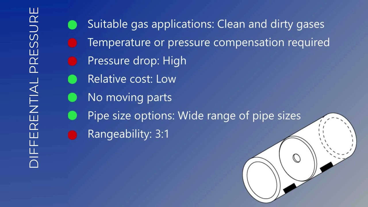
▶️ A Brief Comparison of Thermal Mass Flowmeters and Other Flow Technologies — YouTube

Frequently Asked Questions Your Customers (and Your Sales Team) Are Asking
Technical Questions
“Can thermal mass flow meters measure liquid flow?”
Thermal mass meters are engineered specifically for gas measurement. The fundamental reason is heat transfer physics: gases have low thermal conductivity and low heat capacity, which means a small amount of heater power creates a measurable temperature differential that corresponds to mass flow. Liquids have much higher heat capacity and thermal conductivity, requiring far more power to create a usable signal — and the signal-to-noise relationship is far less favorable.
Some specialized thermal meters exist for specific liquid applications (low-flow deionized water in semiconductor manufacturing, for example), but these are niche products, not general-purpose instruments. For your customers measuring liquid flow, recommend electromagnetic meters for conductive liquids (water, aqueous chemicals), Coriolis for high-accuracy mass flow of any liquid, or turbine/positive displacement for stable liquid viscosities. Recommending thermal mass for liquid applications — unless the customer has a very specific low-flow gas-like liquid application — is a technology mismatch that will cost you credibility.
“What’s the difference between mass flow and volumetric flow, and why does it matter to my operation?”
Use a compressed air example: a manufacturing cell requires 80 Nm³/h of compressed air to run its pneumatic tools and actuators. At 7 bar operating pressure, the volumetric flow in the distribution pipe is about 10 m³/h. At 6.5 bar (pressure drop during peak demand), the same mass of air occupies slightly more volume — the volumetric flow indicator reads slightly higher even though no more air is actually flowing. Your customer’s compressor controls are responding to a signal that doesn’t accurately represent actual consumption.
Mass flow tells you how many kilograms (or standard cubic meters, which is mass-equivalent) of gas moved through the meter. This is what the compressor generated, what the process consumed, and what appears on the energy bill. It’s the correct basis for energy accounting, combustion control, and leak detection — all of which are ultimately mass-based decisions.
“Do thermal mass meters require straight pipe runs like other technologies?”
Thermal mass meters require 10–20 pipe diameters of straight, unobstructed pipe upstream and 5 diameters downstream — less demanding than vortex meters (15–20D) and comparable to turbine meters. For retrofit applications in congested mechanical areas, insertion-type thermal mass meters can often be installed with a hot-tap fitting without pipe modification, using a flow conditioner to manage short upstream runs. This installation flexibility is a genuine advantage in brownfield projects where straight run is limited.
Contrast this with orifice plates, which require 20–40 pipe diameters upstream depending on the upstream fitting geometry, and flanged connections that require cutting pipe and breaking into the system. In a plant where the piping is already built, the difference between “hot-tap installation in a morning” and “significant pipe modification with shutdown” is a significant project cost factor.
“How do thermal mass meters handle pulsating flow or turbulent conditions?”
Reciprocating compressors generate pulsating flow — the air flow ripples at the compressor’s cycling frequency rather than being smooth. Pulsation can affect the accuracy of thermal mass meters if the pulsation frequency and amplitude are not considered in the installation design.
Mitigation options include: installing the meter downstream of a receiver tank or surge vessel (which dampens pulsation effectively), using a flow conditioner upstream of the meter, or selecting a meter with a sufficient response time that it averages out high-frequency pulsation naturally. Most industrial compressed air systems have receiver tanks that reduce pulsation to acceptable levels by the time the air reaches distribution piping. For direct discharge from a small reciprocating compressor without a receiver — a less common but real installation scenario — discuss pulsation dampening with your supplier’s applications engineer before specifying.
“What happens to thermal mass meter accuracy if the fluid composition changes?”
This is one of thermal mass’s most important advantages for biogas, landfill gas, or variable-composition process gas applications. The thermal mass measurement depends on the gas’s thermal properties (specific heat and thermal conductivity), which do vary with composition. However, the meter measures mass — not energy content or moles of a specific component — and the mass measurement remains accurate regardless of composition changes, as long as the meter has been calibrated for the range of compositions expected.
For biogas applications where methane content varies between 55% and 70%, a thermal mass meter calibrated for a representative midpoint composition (e.g., 62% CH₄) will introduce a small error of ±1–3% across the full composition range — far better than a volumetric meter, which cannot account for composition changes at all and gives a reading that’s accurate only for the specific density it was calibrated at.
Application and Selection Questions
“Our current system uses DP meters for natural gas measurement. Should we upgrade to thermal mass?”
The honest answer depends on which applications you’re metering. For custody transfer at the utility connection: no, the regulatory requirement for approved technology (AGA-3 orifice or AGA-7 turbine) stands, and thermal mass is not the right answer for that point.
For everything downstream — sub-metering of buildings, metering to individual production lines, burner control feedback, leak detection — thermal mass is the better technology in most cases. A phased approach makes sense: identify the highest-value DP applications (the ones with the worst low-flow accuracy, the most maintenance cost, or the most critical process control requirement) and calculate the ROI for those specific points. Let the numbers decide rather than making it an all-or-nothing decision.
“We need to measure compressed air consumption across multiple production lines. What’s the best approach?”
Install one main meter at the compressor room outlet to track total facility consumption, then insert thermal mass meters on the branch headers serving each production zone. The zone-level meters give you cost allocation by production department and the ability to identify which zones have the highest consumption per unit of output — the data that drives efficiency improvement.
Insertion-type thermal mass meters are the practical choice for branch meter points: they’re economical ($1,500–$3,500 installed per point), easy to add to existing piping without major modification, and provide the 100:1 turndown needed to measure accurately from weekend standby consumption to full-production peak demand. Ten meter points across a manufacturing facility, providing data that identifies 20% of compressed air as waste (a typical finding), typically yields a payback period of 18–24 months on the metering investment alone.
“What’s the best flow meter for measuring biogas from our anaerobic digester?”
Thermal mass is the correct primary technology for biogas flow measurement. Three characteristics make it the best fit: it measures mass directly (which is what you need for energy content accounting), it handles variable gas composition without recalibration, and it is available in construction materials compatible with H₂S-bearing wet gas (316L SS or Hastelloy C-276 with appropriate process connections).
The specific installation requirements for biogas include: a moisture separator upstream of the meter (biogas is typically saturated with water vapor, and liquid water ingestion will damage the sensor), a coalescing filter for entrained solids, and sensor construction rated for H₂S in the concentrations present. These are standard accessory specifications, not exotic requirements. A biogas metering package from a competent manufacturer includes all three. See Jade Ant Instruments’ thermal flow meter specifications for construction options available for corrosive gas service.
“Our application has high temperatures and corrosive gases. Can thermal mass handle this?”
The sensor temperature range for standard industrial thermal mass meters is typically -20°C to +200°C process gas temperature. High-temperature designs extend this to 450°C or above. For corrosive gas streams, the specification question is the chemical compatibility of the wetted sensor materials.
Hastelloy C-276 sensors handle: chlorine (dilute), hydrogen sulfide, sulfuric acid vapor, hydrochloric acid, and most mixed industrial acid gas streams. Inconel 625 is specified for oxidizing acid environments. PTFE-coated designs are available for applications where metallic surfaces are not acceptable. Document your customer’s exact gas composition — including trace components — and verify material compatibility before specifying. Most reputable manufacturers have application engineers who will confirm material compatibility against a process gas composition sheet.
Cost and ROI Questions
“Thermal mass meters cost more upfront than volumetric meters. How do I justify the additional expense?”
Build a TCO model using your customer’s specific numbers. The five inputs you need are: what is their current annual maintenance cost for the metering they’re replacing, what percentage of operating time are they in the flow range where their current meter is inaccurate (below 30% of range for an orifice plate, for example), what is the financial impact of that inaccuracy (in energy waste, over-procurement, or billing disputes), what is the installed cost of thermal mass versus the alternative, and how many years before replacement does the customer expect the meter to last?
In compressed air applications, the energy savings component often dominates the ROI calculation. A facility discovering and fixing a 500-CFM compressed air leak (detected because they now have accurate metering that shows the discrepancy between compressor output and production-area consumption) saves $15,000–$20,000/year in energy. Against a thermal mass meter installation cost of $4,000, the ROI is measured in weeks, not years.
“How long does it take to recover the investment in upgrading from DP to thermal mass meters?”
Payback periods in documented industrial cases range from 8 months (high-maintenance DP installations with frequent impulse line problems) to 3 years (well-maintained DP installations in clean gas service). The factors that accelerate payback: high current maintenance cost, frequent calibration requirements, significant low-flow measurement inaccuracy, and energy savings from improved accuracy in metered processes.
Use the following framework for a quick customer payback estimate: multiply their annual DP maintenance cost by 10 years, add 10% of annual gas cost (as a conservative estimate of measurement error value in variable-demand applications), and compare that total against the thermal mass installation cost. If the 10-year maintenance + error cost exceeds the thermal mass capital cost by a factor of 2 or more, the business case is compelling. In most industrial applications, it does.
“What’s included in the lifecycle cost of a thermal mass flow meter?”
A complete lifecycle cost includes: initial purchase price, installation cost (piping, wiring, commissioning), annual calibration (typically every 1–3 years in clean gas service, factoring in removal, shipping, and reinstallation time), sensor cleaning if required by the application, electronics calibration, and eventual sensor replacement (typically at 5–10 years depending on operating environment). Compare this against the DP lifecycle including orifice plate inspection and replacement, impulse line maintenance, valving replacement, and transmitter calibration.
For a thermal mass meter in clean compressed air service: installation $1,500–$2,500, calibration every 2 years at $400–$600 including labor, no other maintenance for the first 5–7 years. Total 10-year cost: $5,500–$7,500. For the equivalent DP installation: $1,500–$2,000 in annual impulse line maintenance, biennial orifice plate inspection, and three or four transmitter calibration events over 10 years typically totals $16,000–$22,000 in maintenance-related spending.
Implementation and Support Questions
“How difficult is it to install a thermal mass flow meter in our existing compressed air system?”
Insertion-type thermal mass meters are designed for retrofit installation. The process is: drill a hole in the pipe (or use a hot-tap fitting for pressurized installation without shutdown), insert the probe to the specified depth, tighten the compression fitting, connect the 24V DC power and signal wiring, configure the meter for the pipe diameter and operating conditions, and verify the reading against a reference if available. A competent instrumentation technician can complete a typical insertion installation in 2–4 hours. No pipe cutting, no flanges, no welding.
Flanged in-line thermal mass meters — where the meter is a spool piece that becomes part of the pipe — require breaking the pipe and bolting in a replacement section. This requires a planned shutdown, but the installation itself is straightforward once the shutdown is scheduled. For new piping systems, in-line designs are the preferred option for cleanest installation.
“What kind of maintenance do thermal mass meters require, and how often?”
In clean gas service (compressed air with good filtration, dry natural gas, nitrogen), a thermal mass meter in good installation conditions may require only annual inspection for physical condition and a calibration check every 2–3 years. No impulse lines to check, no moving parts to service, no orifice bores to inspect for wear.
In gas streams with particulates or condensate contamination, sensor cleaning — removing the sensor probe and cleaning the element with an appropriate solvent — may be required every 6–12 months. This is a 30-minute procedure that does not require sending the meter to a calibration lab. Modern meters with self-diagnostic capability can detect sensor fouling and alert maintenance before measurement accuracy is compromised.
“Do you offer training and technical support to help us get the most from our investment?”
This is the question that separates suppliers who understand the distributor relationship from those who don’t. At Jade Ant Instruments, distributor and agent support includes application engineering consultation — working through specific customer applications before you commit to a recommendation — technical training for your sales and service team covering measurement principles, installation requirements, and troubleshooting, and post-installation commissioning support for complex or critical applications. The goal is to make your team technically capable enough to win and retain accounts through knowledge, not just through price.
Glossaire des termes clés
| Term | Plain-Language Definition |
|---|---|
| Mass Flow | The mass of gas flowing per unit time (kg/h or lb/h) — what the compressor actually generated, independent of temperature and pressure |
| Volumetric Flow | The volume of fluid flowing per unit time (m³/h or CFM) — accurate for liquids, misleading for compressible gases |
| Turndown Ratio (Rangeability) | The ratio of maximum to minimum measurable flow at specified accuracy. 100:1 means accurate from 100% of range down to 1% |
| Differential Pressure (DP) Meter | A flow meter that measures the pressure drop across a restriction (orifice plate, venturi) to calculate flow rate |
| Thermal Conductivity | A gas property that describes how well it conducts heat — a key variable in thermal mass measurement that varies by gas composition |
| T90 Response Time | The time required for a meter to reach 90% of its final value after a step change in flow — a practical measure of measurement speed |
| AGA-3 / AGA-7 / AGA-9 | American Gas Association standards governing orifice plates, turbine meters, and ultrasonic meters respectively for natural gas custody transfer |
| API MPMS | American Petroleum Institute Manual of Petroleum Measurement Standards — governing oil and gas custody transfer measurement |
| Nm³/h | Normal cubic meters per hour — volumetric flow rate expressed at standard reference conditions (0°C, 1 atm), equivalent to a mass-based measurement |
| TCO (Total Cost of Ownership) | Complete cost of an installation over its operating life, including purchase, installation, maintenance, calibration, and downtime costs |
| Hot-Tap Installation | Installing an insertion meter into a pressurized pipe without shutting down the process — using a fitting that allows the probe to be inserted under pressure |
| Impulse Lines | Small-bore tubing connecting a DP transmitter to the process pipe taps — a maintenance-intensive component of DP meter installations |
Your Competitive Advantage in a Crowded Market
The Distributor’s Edge: Why Technical Knowledge Wins Deals
Flow meter distribution is not becoming more commoditized — it’s becoming more stratified. At the low end, price-driven transactions for standard catalog products are under pressure from direct manufacturer sales, online distributors, and international competition. At the high end, technically complex applications with critical performance requirements reward distributors who can diagnose, specify, justify, and support the right solution.
The distributors who are growing in this market consistently share one characteristic: they have deeper application knowledge than their customers, and they demonstrate it in every interaction. They don’t quote product numbers — they ask about the process, identify the real requirement, and come back with a recommendation that solves the customer’s actual problem. That’s what converts a one-time transaction into a 10-year supplier relationship.
This guide is a starting point for that technical depth in thermal mass flow measurement. Use it as training material for new account managers, as a reference for your applications engineers, and as the foundation for customer-facing tools specific to your market.
Your Next Steps: Building a Thermal Mass Flow Meter Practice
Immediate actions (this week): Identify your top five active prospects where gas flow measurement is a current or upcoming requirement. For each one, map their application against the decision matrix in this guide and identify whether thermal mass is the right recommendation. If it is, use the TCO framework to build a simple financial case using their approximate operational numbers.
Medium-term strategy (next 90 days): Build one documented case study from an existing thermal mass installation in your customer base. Get the specific numbers: what were they paying in maintenance before, what is the current maintenance cost, did the measurement accuracy improvement generate any identifiable operational savings? One real case study with real numbers is worth more in your sales process than the entire body of manufacturer marketing literature.
Partnership strategy: Work with your manufacturer partner — including resources available through Jade Ant Instruments’ distributor support framework — to access application engineering support for complex opportunities, technical training for your team, and co-marketing resources for your specific industry verticals.
Additional Resources:
- Jade Ant Instruments Thermal Flow Meter Product Page
- Thermal Air Flow Meters Compared: 2026 Guide — Jade Ant Instruments
- Flow Meter Selection Guide — Jade Ant Instruments
- Sage Metering — 9 Thermal Mass Flow Meter Advantages
- Fox Thermal — Thermal Mass vs. Competing Technologies
- Fluid Components International — Flow Meter Selection for Improved Gas Measurements
- EPI — Flow Meter Technology Comparison
- ISA — Certified Control Systems Technician (CCST)
Schedule Your Team’s Technical Training Session Today
Your team’s ability to confidently recommend the right technology is the difference between winning on expertise and losing on price. If you’re ready to build that capability in thermal mass flow measurement, the next step is a conversation with our application engineering team.
→ Schedule a Customized Training Session for Your Sales and Technical Team
→ Download Our Interactive Decision Matrix and ROI Calculator
→ Request a Technical Consultation for Your Most Challenging Customer Application