A comprehensive guide to calibration best practices, preventive maintenance schedules, and troubleshooting strategies that help B2B distributors and agents maximize ROI, minimize downtime, and deliver superior performance to their end-user clients.
Why Coriolis Flow Meter Maintenance Matters for Your Business
For flow meter distributors and agents, the way your end-user clients maintain their Coriolis meters reflects directly on your reputation. When a meter drifts by 0.3% in a refinery blending operation, that error doesn’t look like a calibration failure — it looks like you sold them the wrong product. When a pharmaceutical client fails an FDA audit because their calibration records are incomplete, they won’t blame their technicians first.
This is the commercial reality of selling and supporting Coriolis flow meters: your clients’ operational results are inseparable from their maintenance practices, and your clients’ maintenance practices are shaped largely by the knowledge and support system you provide them.
Industry data reinforces the financial stakes. According to plant reliability studies, unplanned downtime in process industries costs an average of $250,000 per hour in heavy industrial segments. A Coriolis meter that fails without warning in a custody transfer application doesn’t just cause a shutdown — it triggers commercial disputes, compliance reviews, and contract renegotiations. Meanwhile, a well-maintained Coriolis meter can operate accurately for 10–15 years, according to published lifespan data, delivering consistent ROI to your client and a defensible reason for them to purchase their next meter from you.
This guide is written specifically for distributors, agents, and service teams who support Coriolis flow meters in the field. It covers everything from pre-installation baseline documentation through advanced predictive maintenance strategies — with enough technical depth to train technicians and enough commercial framing to help you build differentiated service packages.
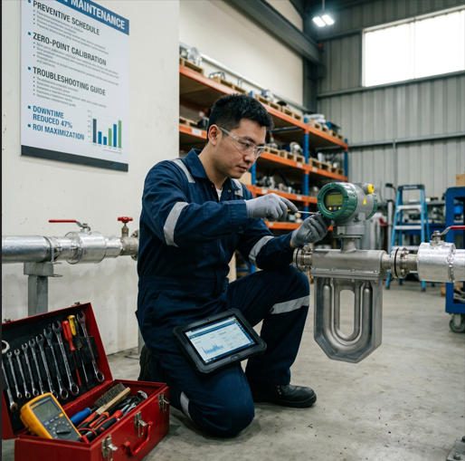
 A Coriolis mass flow meter installed on an industrial pipeline. Proper installation and baseline documentation are the foundation of a long, accurate service life.
Section 1: Understanding Your Coriolis Flow Meter
How Coriolis Flow Meters Work and Why Maintenance Is Critical
Before you can build a credible maintenance program — or explain one to a client — you need a firm grasp of what’s actually happening inside a Coriolis meter and why specific failure modes occur.
The Core Components of a Coriolis Flow Meter
A Coriolis flow meter measures mass flow directly using the Coriolis effect — the same physical principle behind the rotation of weather systems on Earth. When fluid flows through one or more vibrating tubes, the mass of the fluid interacts with the vibration to create a measurable phase shift or twist. The magnitude of that twist is proportional to mass flow rate. This makes Coriolis meters fundamentally different from volumetric meters: they measure mass directly, not inferred from velocity profiles or pressure differentials.
The primary mechanical components include vibrating flow tubes (which may be U-shaped, omega-shaped, or straight, depending on the design), drive coils that sustain the tube vibration at its natural resonant frequency, and pickoff sensors (typically electromagnetic coils or fiber optic sensors) positioned upstream and downstream that detect the phase shift caused by the Coriolis force. Simultaneously, the vibration frequency changes with fluid density — meaning the meter simultaneously outputs mass flow, density, and temperature from a single measurement element.
Le transmitter electronics convert the raw sensor signals into engineering units. Modern Coriolis transmitters include sophisticated digital signal processing, HART or fieldbus communication, built-in diagnostics, and often a data logger for trend analysis. The pressure housing and wetted materials — typically 316L stainless steel, Hastelloy C-22, or titanium, depending on application — must be chemically compatible with the process fluid over the entire operating temperature and pressure range.
Each component requires specific maintenance attention. Vibrating tubes are the heart of the measurement; any fatigue, coating, or corrosion on the tube walls directly degrades accuracy. Transmitter electronics age and require periodic firmware updates. Seals and gaskets degrade with thermal cycling. Electrical connections corrode, especially in humid or outdoor installations.
Common Failure Points in Coriolis Flow Meters
Understanding where Coriolis meters fail helps you prioritize inspection intervals and explain maintenance recommendations to clients in concrete, financially meaningful terms.
Tube fatigue and vibration-related wear occur gradually in applications with cyclic pressure transients, water hammer, or excessive mechanical vibration from nearby pumps and compressors. A survey of industrial Coriolis failures published by the Instrumentation, Systems, and Automation Society found vibration-induced fatigue to be among the top three causes of tube failure in process environments.
Sensor drift and calibration loss is perhaps the most commercially significant failure mode because it happens silently. A meter that reports 99.7% of actual flow looks accurate enough on the dashboard but costs a refinery client thousands of dollars per day in product discrepancy — loss they often attribute to process variation rather than instrument error until an independent audit reveals the drift.
Corrosion and material degradation are application-specific but devastating. Even a nominally compatible material like 316L stainless steel can suffer localized corrosion when exposed to chloride-containing fluids at elevated temperatures. Hastelloy C-22 and titanium exist precisely because standard materials fail in specific chemical environments.
Electrical connection issues are often underappreciated. A corroded connector or a cable with compromised shielding can introduce signal noise that mimics measurement instability, leading technicians to suspect the sensor when the real problem costs $15 to fix.
Blockages and fluid accumulation occur in meters that are improperly installed at locations where the process fluid can settle, crystallize, or accumulate during shutdowns. Crystalline deposits on tube walls shift the effective tube mass and create a spurious density reading — which then propagates as a mass flow error.
How Neglected Maintenance Impacts Accuracy and Profitability
The economics of neglected Coriolis maintenance are straightforward, even if clients don’t always connect the dots until something breaks. A pharmaceutical client relying on a drifted Coriolis meter for API (active pharmaceutical ingredient) dosing faces batch rejection costs that typically run 5–10× the cost of a calibration service. A custody transfer station with an out-of-spec Coriolis meter faces measurement disputes where even a 0.1% error on a high-volume hydrocarbon line translates to tens of thousands of dollars in annual product discrepancy.
Regulatory compliance risk is equally real. Industries operating under ISO 9001 quality management, FDA 21 CFR Part 11 (pharma), or API MPMS (custody transfer) have explicit requirements for calibration traceability and maintenance documentation. An audit that finds a two-year gap in calibration records isn’t just a compliance problem — it’s potential product recall territory.
For distributors and agents, clients who experience these problems tend to attribute them to equipment quality rather than maintenance gaps. Proactive maintenance education is your most cost-effective warranty management tool.
Section 2: Establishing a Preventive Maintenance Schedule
Build a Maintenance Calendar That Reduces Unplanned Downtime
A maintenance calendar isn’t a document you create once and file. It’s a living operational tool that should be calibrated to the actual risk profile of each installation.
Pre-Installation Inspection and Baseline Documentation
The baseline documentation phase is the single most undervalued step in the entire maintenance lifecycle. When a meter eventually shows an anomalous reading at 3:00 AM during a production run, the first question your technician will ask is: “What did this meter look like when it was new?” Without baseline data, that question has no answer.
The receiving inspection checklist should include verification of the factory calibration certificate (confirming the calibration date, standards used, and accuracy results), visual inspection for shipping damage, confirmation that the serial number matches the certificate, and a dimensional check of process connections. ISO/IEC 17025-accredited calibration is the gold standard; confirm that the factory calibration certificate references a traceable calibration chain.
Before commissioning, perform a live zero-point verification with the meter filled with process fluid but with zero flow. Record this value as your commissioning zero. Photograph the installation, cable routing, and connection wiring. Create a tag in your CMMS (Computerized Maintenance Management System) with all baseline parameters: operating flow range, operating temperature and pressure, zero value, span calibration points, and transmitter configuration. This record becomes the foundation against which all future performance is judged.
Monthly Maintenance Tasks
Monthly checks are designed to catch rapid-onset issues before they become measurement failures. The time investment is minimal — typically 15–30 minutes per meter — but the diagnostic value is disproportionately high.
Visual inspection should cover the meter body for signs of external corrosion, process fluid leaks at flanges or process connections, cable jacket condition, and conduit integrity. Check the display for active alarms or diagnostic codes. Log the current zero value and compare it to the baseline; a zero shift greater than your application’s tolerance is an early indicator of process fluid accumulation or temperature-related stress changes.
Performance data trending is the most powerful monthly tool. Plot mass flow, density, and temperature outputs over time. Gradual density drift without corresponding temperature changes suggests coating or deposit buildup inside the measurement tubes — something that won’t show up on any visual inspection but is reliably detected by trending density against process temperature.
Quarterly Maintenance Procedures
Quarterly maintenance moves from observation to diagnosis. This is where trained technicians use meter-level diagnostic tools to assess sensor health, signal quality, and electronic integrity.
Modern Coriolis transmitters include built-in verification routines that check drive gain, pickoff signal strength, and tube resonant frequency against factory baselines. Running these diagnostics quarterly and logging the results creates a longitudinal health record for the meter. A drive gain value that increases 15% over six months indicates tube coating — providing enough warning to schedule a cleaning outage before the coating causes measurement error.
Electrical connection verification at the quarterly interval should include checking cable shielding continuity, connector integrity, terminal block tightness, and grounding resistance. In outdoor or humid installations, connector corrosion is a quarterly-frequency failure mode, not an annual one.
Annual Maintenance and Recalibration Requirements
Annual maintenance is where the full calibration and mechanical inspection cycle occurs. This is also the natural budget planning point for replacement parts, calibration services, and service contracts.
A full calibration procedure for a Coriolis meter involves verifying the zero-point, performing a span calibration against a traceable reference standard, and checking multi-point accuracy across the operating flow range. For most industrial applications, ISO/IEC 17025-accredited laboratory calibration provides the highest level of documented accuracy confidence. For applications where removing the meter is not practical, in-situ calibration against a portable transfer standard is a viable alternative with appropriate uncertainty budgeting.
Seal and gasket inspection at the annual interval is non-negotiable. Process connection seals that have experienced a full year of thermal cycling and pressure variation should be inspected and replaced according to the manufacturer’s specification, not based on whether they “look okay.”
Extended Maintenance Intervals (Every 3–5 Years)
Every three to five years, the maintenance program should include a strategic review that asks harder questions than “is this meter working?” The more relevant questions are: Is this meter still the right technology for this application? Have the process conditions changed enough to warrant a different wetted material? Are diagnostic and communication capabilities still aligned with the plant’s asset management strategy?
A meter that was installed 10 years ago with HART 5 communication may be limiting your client’s ability to integrate condition monitoring into their CMMS. Upgrading the transmitter electronics — without replacing the flow sensor — is often a cost-effective modernization path that extends the meter’s effective life while delivering current capabilities.
Section 3: Calibration Best Practices
Master Calibration Procedures to Maintain Accuracy Standards

Understanding Calibration Drift and Accuracy Degradation
Calibration drift — the gradual departure of a meter’s output from its true value — is an inevitable consequence of operating in a real process environment. Understanding its root causes helps you select appropriate calibration intervals and explain the rationale to clients who resist the cost.
The primary causes of calibration drift in Coriolis meters include sensor aging (changes in the electromagnetic properties of pickoff coils and drive elements over years of thermal cycling), temperature-induced stress (particularly in installations with wide seasonal temperature swings), vibration fatigue (especially near rotating equipment), fluid contamination (deposits that shift the effective tube mass), and electronic component drift (capacitors and resistors whose values change with age and temperature).
Industry standards define acceptable drift tolerances by application. API MPMS, chapitre 5 for custody transfer applications requires calibration verification at intervals not exceeding one year, with drift limits of ±0.02% for fiscal measurement. Pharmaceutical applications under USP guidelines require calibration records with documented traceability and defined acceptance criteria specific to each process.
In-Situ Calibration Methods for Minimal Downtime
Zero-point calibration — re-establishing the baseline reading when no flow is present — is the most frequently performed calibration procedure and the one most accessible to trained field technicians. To perform it correctly, the meter must be completely filled with process fluid, all flow must be stopped (not just reduced), and the fluid must be at thermal equilibrium. Many measurement errors attributed to “meter drift” are actually zero-point offsets that can be corrected in 10 minutes by an informed technician.
Span calibration — verifying accuracy across the measurement range — requires a reference standard. In the field, this is typically accomplished using a portable master meter (often itself a Coriolis meter with a current calibration certificate) or a gravimetric reference system for high-precision applications. Multi-point calibration, verifying at 10%, 50%, and 100% of rated flow, provides the most complete picture of meter performance and is required for custody transfer applications.
Laboratory Calibration vs. On-Site Calibration
The choice between laboratory and on-site calibration involves a balance of accuracy, cost, and operational risk. Laboratory calibration — sending the meter to an ISO/IEC 17025-accredited facility like Southwest Research Institute — provides the highest measurement uncertainty and the most legally defensible documentation. It also requires removing the meter from service, which may trigger process isolation procedures, vessel draining, and production downtime.
On-site calibration using portable transfer standards avoids this downtime and is technically adequate for most industrial process measurement applications. The limitation is that portable standards introduce their own measurement uncertainty, which must be budgeted into the overall calibration result. For custody transfer and high-precision pharmaceutical applications, laboratory calibration remains the recommended approach.
A practical framework for distributors: recommend laboratory calibration for meters in custody transfer, fiscal measurement, and critical pharmaceutical quality control applications. Recommend on-site calibration for process control and inventory tracking applications where ±0.1–0.5% accuracy is adequate. Document this recommendation in your service contracts so clients understand the rationale.
Establishing Your Calibration Standard Operating Procedures (SOPs)
SOPs are the foundation of consistent, defensible service delivery across your entire team. A calibration SOP for Coriolis meters should specify the tools required, the step-by-step procedure, acceptance criteria, documentation format, and escalation path when results fall outside tolerance.
Traceability is the critical element. Every calibration result must be traceable — through an unbroken chain of comparisons with stated uncertainties — to a national measurement standard. NIST maintains primary flow calibration standards that are the ultimate reference for US-based calibrations. Ensure that every piece of calibration equipment your team uses has a current calibration certificate referencing NIST or an equivalent national metrology institute.
Client communication templates for calibration results should include the calibration date, technician name and certification status, equipment used with their calibration certificates, as-found readings, as-left readings, and a clear pass/fail statement against the application acceptance criteria. This documentation format serves both compliance requirements and your relationship with the client — it demonstrates professional competence in a way that a simple “meter checked — okay” entry in a logbook does not.
Section 4: Troubleshooting Common Issues
Diagnose and Resolve Problems Quickly to Minimize Client Impact
The difference between a distributor who is valued as a technical partner and one who is seen as simply a product vendor is often the speed and confidence with which their team resolves problems. Troubleshooting competence is a competitive differentiator.
Identifying and Fixing Measurement Errors
Sudden measurement spikes or drops — step changes in the output that don’t correspond to process changes — are almost always signal or electronics problems. The diagnostic sequence begins with the transmitter diagnostic display: check for active fault codes, drive gain abnormalities, and pickoff signal levels. If all diagnostics are clear, proceed to inspect cable connections and check for EMI sources that may have recently been introduced nearby (new VFDs, welding operations, high-power motor starts).
Gradual drift, by contrast, is typically either a calibration issue (zero shift, span change) or a process issue (fluid accumulation, temperature change, coating buildup). The diagnostic tool here is trend data. If you have a year of density readings, plot them against process temperature. A density that has increased 0.5 kg/m³ without a corresponding temperature change is a strong indicator of deposit accumulation inside the measurement tubes.
Inconsistent zero-point readings — a zero value that changes from test to test — indicate either incomplete flow stoppage during the zero check (the most common cause), residual vibration from nearby equipment, or entrained gas in the measurement tubes at low flow conditions.
Resolving Sensor and Signal Problems
Signal quality diagnostics in modern Coriolis transmitters provide quantitative data on pickoff signal strength, drive gain, and tube resonant frequency. These values are measurable and trend-able — use them. A drive gain that has increased from its factory baseline of 12% to 25% over 18 months is telling you something is changing inside the meter (coating, corrosion, or temperature-induced tube stiffness change). You have time to plan a corrective action. A drive gain that jumps to 80% in a week is telling you something has failed acutely.
Frequency shift issues — the tube resonant frequency changing from its baseline — indicate either a significant change in fluid density or a change in tube mechanical properties (corrosion, damage, or temperature-induced stress). If the process fluid hasn’t changed and temperature is stable, an unexpected frequency shift is a serious diagnostic finding that warrants immediate investigation and potentially removing the meter from service.
Addressing Fluid-Related Issues
Cavitation — the formation and collapse of vapor bubbles in the process fluid — is one of the most damaging phenomena a Coriolis meter can experience. Cavitation occurs when local fluid pressure drops below the fluid’s vapor pressure, typically at the inlet of the meter where the flow profile accelerates. The bubble collapse creates localized pressure transients that can damage tube walls, erode wetted surfaces, and generate signal noise that looks identical to measurement instability.
Prevention is straightforward: maintain adequate inlet pressure (at least 2× the process fluid’s vapor pressure at operating temperature), use properly sized backpressure valves on the meter outlet, and avoid installations immediately downstream of pump discharge where pressure transients are common.
Crystallization and deposit buildup require cleaning procedures appropriate to the specific deposit chemistry. Salt deposits can often be dissolved with a water flush. Polymeric or waxy deposits may require solvent cleaning or elevated temperature flushing. Always verify that the cleaning chemical is compatible with all wetted materials — a cleaning chemical that dissolves the deposit but attacks the flow tube materials creates a worse problem than the deposit itself.
Handling Vibration and Mechanical Problems
Mechanical vibration is the Coriolis meter’s most persistent environmental adversary. Because the measurement principle relies on detecting small phase shifts in tube vibration, external vibration at or near the tube’s resonant frequency can either add noise to the signal or — in extreme cases — lock the drive system into an externally-driven frequency rather than the meter’s natural resonant frequency.
The diagnostic symptom is typically increased signal noise (high flow output noise on the transmitter display) that correlates with the operation of nearby rotating equipment. The solution hierarchy is: first, verify that the meter is properly mounted with sufficient mechanical isolation from the pipeline; second, add vibration isolation mounts between the meter and its support structure; third, evaluate whether the meter’s installation location can be moved away from the vibration source.
Section 5: Maintenance Tools and Equipment
Equip Your Team With the Right Resources for Professional Service
 Proper diagnostic equipment transforms maintenance from guesswork into evidence-based decision making. A well-equipped service team is a marketable competitive advantage.
Essential Tools for Coriolis Flow Meter Maintenance
The minimum equipment set for a Coriolis flow meter service team includes a true-RMS digital multimeter capable of measuring AC and DC voltage, current (4–20 mA loop), and resistance for signal circuit testing; a HART communicator or PC-based HART interface for accessing transmitter diagnostics and configuration; calibrated pressure gauges for inlet/outlet pressure verification; portable calibration reference meter with a current ISO/IEC 17025 calibration certificate for in-situ span verification; and appropriate PPE including chemical-resistant gloves and face protection for any application involving hazardous process fluids.
The HART communicator deserves particular emphasis. Modern Coriolis transmitters store diagnostic history, configuration records, and calibration data in formats accessible via HART. A technician who can read and interpret this data has a diagnostic capability that’s orders of magnitude greater than one relying only on the front-panel display.
Recommended Diagnostic Equipment
Un oscilloscope allows direct visualization of the pickoff sensor waveforms, enabling qualitative assessment of signal quality, noise characteristics, and waveform symmetry that cannot be seen in summarized diagnostic values. For troubleshooting signal quality problems, this is often the definitive diagnostic tool.
Thermal imaging cameras (infrared cameras) identify hot spots at electrical connections, insulation failures on heating systems, and conduit penetrations where moisture may be entering. A 10-minute infrared scan of an outdoor meter enclosure can identify corrosion-related resistance increases in connections that would take hours to find through conventional resistance measurement.
Data logging equipment — even a simple USB datalogger connected to the 4–20 mA output — enables continuous performance monitoring between maintenance visits. Clients who can see a trend of their Coriolis meter’s performance over six months are far more receptive to maintenance recommendations than those who receive a report of instantaneous test results.
Building Your Service Kit
Spare parts inventory should be strategically sized to the installed base you support. For Coriolis meters, the highest-priority spare parts are process connection gaskets and seals (which should be replaced at every annual service), cable gland assemblies for outdoor and hazardous area installations, transmitter terminal blocks and connector assemblies, and — for applications with known corrosion risk — a complete sensor replacement unit of the most commonly installed meter size.
Quick-reference troubleshooting charts, laminated and placed in service kits, reduce diagnostic time in the field and ensure that junior technicians follow a consistent diagnostic sequence rather than guessing. These charts should map from observable symptoms to probable causes to recommended diagnostic steps — with clear escalation criteria for issues that require factory support.
Section 6: Preventive Maintenance Best Practices
Implement Strategies That Maximize Equipment Lifespan and Performance
Environmental Monitoring and Control
Temperature stability is the most underappreciated environmental factor in Coriolis meter performance. The meter’s tube resonant frequency — and therefore its density measurement — is temperature-sensitive. Most transmitters include temperature compensation algorithms, but these assume the temperature sensor accurately represents the fluid temperature throughout the measurement tube. In applications with large temperature gradients (e.g., outdoor installations in climates with significant seasonal variation), thermal management — insulation or heat tracing — is a maintenance-enabling investment rather than a luxury.
Humidity and moisture management matters particularly for meters installed outdoors or in washdown environments. Even IP67-rated enclosures eventually accumulate moisture through thermal breathing cycles — the pressure differentials created when warm electronic enclosures cool and contract. Annual inspection and replacement of conduit seals, combined with periodic desiccant replacement in junction boxes, is the preventive strategy.
Fluid Management Strategies
Pre-filtration upstream of the Coriolis meter is one of the highest-value investments your clients can make for protecting meter performance. A 50-micron inline strainer upstream of a Coriolis meter in a slurry or particle-laden fluid application can reduce tube erosion rates by 80% and extend calibration intervals from quarterly to annual. The strainer itself requires periodic cleaning, but that maintenance task is far cheaper than meter replacement.
Regular fluid analysis — particularly for applications where fluid composition changes seasonally or with batch lot variations — provides early warning of compatibility issues. If a petrochemical client’s feed stock changes suppliers and the new fluid has a slightly different chloride content, a periodic fluid analysis can identify the compatibility risk before the meter wetted surfaces begin to corrode.
Documentation and Record Management
A well-maintained maintenance record is simultaneously a compliance document, a technical diagnostic database, and a commercial asset. When a client’s quality manager reviews calibration records during an internal audit and sees five years of complete, well-organized documentation with NIST-traceable calibration certificates, appropriate corrective actions for out-of-tolerance findings, and trend data showing consistent meter performance — that’s a service relationship they’re unlikely to move to a competitor.
Digital CMMS platforms offer significant advantages over paper systems for Coriolis meter maintenance: automatic calibration due date alerts, searchable history by serial number, photo documentation storage, and report generation for client audits. The investment in a good CMMS platform pays back in reduced administrative labor and dramatically improved audit readiness.
Section 7: Training Your Team and Supporting Your Clients
Build Expertise and Credibility Through Professional Development
Developing a Technician Training Program
The core competencies for a Coriolis meter service technician cover five areas: measurement theory (understanding the Coriolis principle deeply enough to reason about failure modes, not just follow procedures), calibration procedures (both zero-point and span, with understanding of traceability requirements), transmitter configuration and diagnostics (HART communication, diagnostic parameter interpretation, firmware update procedures), troubleshooting methodology (systematic root cause analysis rather than symptom substitution), and safety protocols (process isolation, confined space procedures, chemical hazard management).
Endress+Hauser’s calibration training resources and Emerson’s Micro Motion training programs both offer manufacturer-specific certification that provides credibility with end-user clients. These certifications also ensure your team’s procedures are current with the latest transmitter software and diagnostic capabilities.
Creating Client Education Materials
End-user maintenance guides should be written at the level of a process operator or instrument technician who has general instrumentation training but may not be a Coriolis specialist. The most effective format combines concise written procedures with decision flowcharts that guide the reader through diagnostic sequences without requiring them to hold the full troubleshooting logic in their head.
Video tutorials — particularly for procedures like zero-point calibration and HART diagnostic access — dramatically reduce training time and ensure consistent technique across client sites with multiple technicians. A 4-minute video demonstrating correct zero-point calibration procedure on a specific transmitter model is more effective than three pages of text instructions.
Building a Maintenance Support System
Response time standards are a competitive differentiator in the distributor and agent market. A client whose Coriolis meter is showing a fault code at 2:00 AM during a critical production run needs to know whether they’re dealing with a nuisance alarm or an imminent shutdown. A 24-hour phone support line staffed by technically competent people — not just call-takers who escalate to engineers the next morning — is the type of support capability that earns long-term client loyalty.
Remote diagnostic capability, using modern HART or fieldbus connectivity to access transmitter diagnostics from a central support office, can often resolve a client’s alarm situation without dispatching a technician. This reduces your cost, reduces client downtime, and demonstrates technical sophistication that generic competitors can’t easily replicate.
Section 8: Cost Analysis and ROI Optimization
Demonstrate Business Value Through Smart Maintenance Investment
Calculating the True Cost of Ownership
The total cost of ownership (TCO) model for a Coriolis flow meter includes several components that are typically under-appreciated in the initial purchasing decision. A typical industrial Coriolis meter with a purchase price of $8,000–$25,000 (depending on size, materials, and communications) will accumulate maintenance costs over a 15-year service life as follows:
| Élément de coût | Estimated 15-Year Cost | Remarques |
|---|---|---|
| Initial equipment + installation | $10,000–$30,000 | Includes meter, transmitter, process connections, labor |
| Annual calibration services | $1,500–$4,500 | $100–$300/year × 15 years; lab calibration higher |
| Preventive maintenance labor | $3,000–$7,500 | 2–5 hours/year at $100–$150/hour field rate |
| Spare parts (seals, gaskets, connectors) | $500–$2,000 | Varies by application severity |
| Unplanned repairs (statistically) | $2,000–$8,000 | Highly variable; 0–2 events over 15 years |
| Downtime cost (if poorly maintained) | $10,000–$100,000+ | Application-dependent; custody transfer highest |
| Total TCO (maintained vs. neglected) | $17,000–$42,000 maintained | vs. $27,000–$140,000+ neglected |
The economic case for preventive maintenance is clear: a well-maintained meter’s total lifecycle cost is a fraction of one that operates reactively. The largest single driver of cost difference is unplanned downtime — which preventive maintenance directly reduces.
Building Maintenance Service Packages
Tiered service packages allow clients to select a support level commensurate with their application criticality and risk tolerance. A three-tier structure typically works well for Coriolis meter distributors:
Basic Coverage includes annual calibration service, calibration documentation, and access to a technical support line during business hours. This is appropriate for non-critical process control applications with adequate accuracy tolerance.
Standard Coverage adds quarterly performance reviews, CMMS integration for calibration scheduling and records management, and next-business-day on-site response to equipment failures.
Premium Coverage includes all Standard elements plus continuous remote monitoring integration, 24/7 support line, 4-hour on-site response guarantee, spare meter availability, and annual strategic review meetings with technical recommendations.
Demonstrating ROI to Your Clients
The most persuasive ROI demonstration uses the client’s own data. One proven approach: at the time of commissioning, document the current calibration status and establish a performance baseline. At the first annual service, present a comparison showing the as-found calibration results, calculate what the measurement error would have cost the client over the year if it had gone uncorrected, and demonstrate that the calibration service fee is typically 5–20% of the avoided cost.
A custody transfer client measuring 1,000 barrels per day of crude oil at $70/barrel who experiences 0.1% measurement drift is losing $25,550 per year in unaccounted product discrepancy. An annual calibration service that detects and corrects that drift — and documents the correction for the fiscal measurement authority — costs a fraction of that number.
Section 9: Compliance and Standards
Meet Industry Requirements and Regulatory Obligations
Understanding Relevant Standards and Certifications
The regulatory landscape for Coriolis meter calibration involves several overlapping standards frameworks. ISO 9001:2015 (Quality Management Systems) applies broadly to any manufacturer or service organization and requires documented maintenance and calibration procedures, controlled records, and competency management for personnel performing technical tasks.
ISO/IEC 17025:2017 is the specific standard for calibration laboratories. If you offer calibration services, or if your clients’ compliance frameworks require it, calibration must either be performed at an ISO/IEC 17025-accredited laboratory or traceable to one. This standard defines technical competency requirements, measurement uncertainty requirements, and documentation standards for calibration results.
NIST traceability is the requirement that calibration results can be traced — through an unbroken chain of comparisons with stated uncertainties — to the National Institute of Standards and Technology. NIST maintains primary flow calibration standards that underpin the entire calibration infrastructure in US industry.
Industry-specific standards add application requirements on top of these foundational frameworks. API MPMS, chapitre 5 governs displacement and Coriolis metering in custody transfer applications. ASME MFC-11 covers Coriolis meter application, installation, and calibration. The EU Measuring Instruments Directive (MID) applies to meters used for commercial transactions within the European Union and requires type approval and periodic reverification.
Documentation and Audit Readiness
Audit readiness is a service you can actively provide to clients. A distributor who helps a pharmaceutical client prepare for an FDA inspection of their flow measurement records — by organizing calibration certificates, corrective action documentation, and calibration procedure SOPs in a format auditors can navigate efficiently — is providing value that has nothing to do with the hardware itself.
Required record retention periods vary by industry: pharmaceutical GxP records typically require 10+ years of retention; custody transfer calibration records are often required for 7 years; ISO 9001 implementations vary. Digital records management systems make long-term retention and retrieval practical in ways that paper systems cannot match.
Section 10: Advanced Maintenance Strategies
Optimize Performance With Predictive and Condition-Based Maintenance

Implementing Predictive Maintenance Programs
Predictive maintenance (PdM) for Coriolis meters uses continuous performance data to predict when maintenance will be needed — shifting from time-based intervention to condition-based intervention. The technology infrastructure for Coriolis PdM is more accessible than it was five years ago: modern HART 7 and fieldbus-capable transmitters can stream diagnostic data to asset management systems continuously, and cloud analytics platforms can apply machine learning to detect anomaly patterns that precede failures.
The key condition indicators for Coriolis meters in a predictive maintenance program are drive gain (increasing drive gain indicates mass change in the measurement system — coating, corrosion, or temperature effect), pickoff signal amplitude (decreasing signal amplitude indicates sensor degradation or connection issues), tube resonant frequency (frequency drift relative to calibration baseline indicates fluid density change or tube mechanical property change), and zero stability (increasing zero instability indicates multi-phase flow, vibration interference, or process fluid accumulation).
Endress+Hauser’s Heartbeat Technology and Emerson’s Smart Meter Verification are examples of manufacturer-integrated condition monitoring tools that generate quantitative health indicators on a scheduled basis without removing the meter from service. These tools are a significant competitive advantage for distributors who can help clients implement and interpret them.
Condition-Based Maintenance Approaches
Condition-based maintenance (CBM) establishes alert thresholds for key performance indicators and triggers maintenance only when thresholds are exceeded. The advantage over time-based maintenance is dual: you don’t perform unnecessary maintenance on meters that are performing well, and you don’t miss critical issues in meters that deteriorate faster than expected.
Implementing CBM for a Coriolis meter fleet requires: establishing quantitative baselines for each meter at commissioning, defining alert thresholds for each diagnostic parameter based on application criticality and acceptable measurement uncertainty, and creating a response protocol that specifies what action is taken when each threshold is exceeded (investigate, calibrate, replace).
Digital Tools and Software Solutions
CMMS platforms (Computerized Maintenance Management Systems) like IBM Maximo, SAP PM, or cloud-based alternatives like UpKeep or Fiix provide the infrastructure for professional Coriolis meter maintenance programs. Key capabilities to look for: equipment hierarchy management, preventive maintenance schedule automation, calibration due-date tracking, work order management, and report generation for client deliverables.
For distributors managing maintenance programs across multiple client sites, a multi-site CMMS with client portal functionality — allowing clients to view their own equipment records and upcoming maintenance schedules — is a significant service differentiator that justifies premium service contract pricing.
The Jade Ant Instruments Approach to Long-Term Flow Measurement Support
 Coriolis meters designed with accessible diagnostic ports and robust transmitter housings are significantly easier to maintain — a specification point worth evaluating during selection.
At Jade Ant Instruments, the support relationship with distributors and agents extends well beyond the initial equipment sale. Our technical team works directly with distribution partners to build application-specific maintenance recommendations, calibration documentation packages, and client education materials that help you deliver differentiated service to your end-user clients.
Our Coriolis and electromagnetic flow meters are specified and documented to support the full maintenance lifecycle described in this guide — from ISO-traceable factory calibration at commissioning through multi-year performance trending in the field. When your client needs a technical resource behind their distributor, we’re structured to provide that depth without competing with your client relationship.
Conclusion
Positioning Your Business as a Maintenance Expert
The distributor and agent market for flow measurement is not won on product specification sheets. At a baseline technical level, multiple manufacturers offer Coriolis meters with comparable accuracy, similar wetted material options, and broadly equivalent communication capabilities. The differentiation is in service competence, technical credibility, and the client’s confidence that problems will be resolved quickly and completely.
A distributor who can look at a trend graph of a client’s Coriolis meter’s drive gain history and immediately identify that the 18-month upward drift correlates with the introduction of a new cleaning protocol — and recommend adjusting the CIP cycle to prevent further coating — is providing a service that no product catalog can replicate. That capability builds partnerships that last decades, not until the next competitive price quote.
The maintenance principles in this guide are not complex in isolation. What makes them powerful is systematic application: baseline documentation, regular calibration with proper traceability, diagnostic trending, trained technicians, and service agreements that structure ongoing support. The distributors who implement these practices consistently will be the ones whose clients call first when they need new equipment — because they’ve already proven they know how to take care of the equipment they have.
Next Steps for Implementation
The practical path from reading this guide to delivering improved maintenance service involves four parallel workstreams. First, audit your current maintenance practices against the framework described here and identify the most significant gaps — likely documentation completeness and calibration traceability. Second, assess your team’s technical training needs, particularly for HART diagnostics, calibration procedures, and troubleshooting methodology. Third, develop or adopt a CMMS system that can support professional maintenance records management and client reporting. Fourth, design your service package offering and identify which of your existing clients would benefit from an upgrade to a more structured maintenance program.
🎬 Recommended Video: How Coriolis Flow Meters Work
Understanding the measurement principle at a fundamental level makes every aspect of maintenance — from vibration troubleshooting to calibration drift analysis — more intuitive.
Video: Coriolis Flow Meter Theory of Operation — a foundational explainer on the measuring principle that underpins all maintenance decisions.
📥 Ready to Transform Your Maintenance Program?
Download our complete Coriolis Flow Meter Maintenance Checklist and get started today. This practical tool includes monthly, quarterly, and annual task lists, troubleshooting flowcharts, and documentation templates — everything your team needs to deliver world-class maintenance service.
[Download Your Free Maintenance Checklist]
Or schedule a consultation with the flow instrumentation specialists at Jade Ant Instruments to discuss a customized maintenance strategy for your business. We’ll help you identify opportunities to reduce downtime, improve accuracy, and maximize ROI for your clients.
📊 Maintenance Interval Summary Table
The following table consolidates maintenance tasks by frequency for quick reference and CMMS programming:
| Task | Mensuel | Quarterly | Annuel | 3–5 Year |
|---|---|---|---|---|
| Visual inspection — body, cables, conduit | ✅ | ✅ | ✅ | ✅ |
| Display alarm check | ✅ | ✅ | ✅ | ✅ |
| Zero-point verification | ✅ | ✅ | ✅ | ✅ |
| Performance data trending (flow, density, temp) | ✅ | ✅ | ✅ | ✅ |
| Drive gain & pickoff diagnostics | ✅ | ✅ | ✅ | |
| Electrical connection integrity | ✅ | ✅ | ✅ | |
| Fluid condition assessment | ✅ | ✅ | ✅ | |
| Full span calibration (ISO traceable) | ✅ | ✅ | ||
| Seal & gasket replacement | ✅ | ✅ | ||
| Transmitter firmware review | ✅ | ✅ | ||
| Thermal imaging of connections | ✅ | ✅ | ||
| Major component inspection / overhaul | ✅ | |||
| Upgrade vs. replacement analysis | ✅ | |||
| Technology obsolescence review | ✅ |
🔖 Glossary of Key Terms
Calibration Drift: The gradual departure of a meter’s measurement output from its true value over time, caused by sensor aging, environmental factors, or process conditions.
CMMS (Computerized Maintenance Management System): Software platform for managing maintenance schedules, work orders, equipment records, and compliance documentation.
Coriolis Effect: The physical phenomenon where a mass moving through a rotating or vibrating frame experiences a force perpendicular to its direction of motion — the measurement principle used in Coriolis flow meters.
Drive Gain: The amount of electrical energy required to maintain tube vibration at the natural resonant frequency. Increasing drive gain indicates mass changes in the tube system (coating, corrosion, or temperature effects).
EMI/RFI (Electromagnetic/Radio Frequency Interference): External electromagnetic fields that can induce noise in flow meter signal circuits, causing spurious measurement readings.
ISO/IEC 17025: International standard defining competency requirements for calibration laboratories, including measurement uncertainty documentation and traceability requirements.
NIST Traceability: The ability to relate measurement results to national measurement standards maintained by the National Institute of Standards and Technology through an unbroken chain of calibrations with stated uncertainties.
Pickoff Sensor: The electromagnetic coil or optical sensor that detects the vibration of the Coriolis meter’s flow tubes and transmits the phase shift signal to the transmitter.
Zero-Point Calibration: The procedure that establishes the meter’s baseline output reading when no flow is present. A key diagnostic indicator of measurement health.
Span Calibration: Verification of meter accuracy across the full measurement range, typically at multiple flow rates, against a traceable reference standard.
Wetted Materials: The materials that come into direct contact with the process fluid inside the flow meter — typically stainless steel, Hastelloy, or titanium, selected for chemical compatibility.
Foire aux questions (FAQ)
1. How often should we calibrate our Coriolis flow meters?
Calibration frequency is determined by application criticality, fluid type, and regulatory requirements. For most industrial process control applications, annual calibration is appropriate and aligns with ISO 9001 quality management expectations. Critical applications — pharmaceutical dosing, custody transfer, fiscal measurement — typically require semi-annual or quarterly calibration intervals. For custody transfer specifically, API MPMS Chapter 5 requires calibration verification at maximum one-year intervals, with many operators choosing 6-month cycles to manage commercial risk. Review manufacturer recommendations, your process specifications, and any applicable regulatory requirements to define the correct interval for each installation. Connecting with experts at Jade Ant Instruments can help distributors structure appropriate calibration recommendations for specific applications.
2. What’s the difference between zero-point and span calibration?
Zero-point calibration establishes the meter’s baseline output measurement when no flow is present — it verifies that the meter reads zero when flow is zero. Span calibration verifies accuracy across the measurement range by comparing the meter’s output against a traceable reference standard at specified flow rates (typically 10%, 50%, and 100% of rated flow). Zero-point calibration can be performed in the field with proper flow isolation and typically takes 10–15 minutes. Span calibration requires a reference standard and is more complex, forming the core of the annual calibration service. Both are essential: a meter with a perfect span calibration but a shifted zero point will be systematically biased in the direction of the zero offset across its entire measurement range.
3. Can we perform calibration on-site, or does it require a laboratory?
Both approaches are technically viable and each has a legitimate role in a maintenance program. On-site (in-situ) calibration using portable transfer standards minimizes process downtime and is appropriate for the majority of industrial process control applications. Laboratory calibration — sending the meter to an ISO/IEC 17025-accredited facility — provides higher measurement confidence and the most defensible documentation, making it the recommended approach for custody transfer, fiscal measurement, and critical pharmaceutical quality control applications. Hybrid programs — in-situ calibration annually with laboratory calibration every 3–5 years — are commonly used in well-managed industrial maintenance programs.
4. What causes measurement drift in Coriolis flow meters?
Coriolis meter drift has multiple root causes, and identifying the specific cause is essential for selecting the right corrective action. Sensor aging — gradual changes in the electromagnetic properties of pickoff coils — is the most fundamental cause and is why periodic recalibration is necessary even in stable installations. Temperature fluctuations affect both tube resonant frequency and fluid density calculations. Vibration from nearby equipment can shift zero stability and introduce span errors. Fluid contamination or deposit accumulation inside measurement tubes changes the effective tube mass and alters the resonant frequency, creating apparent density drift that propagates into mass flow error. Electronic component drift in transmitter signal processing circuits is less common but occurs over 5–10+ year timescales. Regular diagnostic trending — particularly monitoring drive gain and density against temperature — is the most effective early detection tool.
5. How do we prevent cavitation damage in Coriolis meters?
Cavitation in Coriolis meters occurs when fluid pressure drops below the fluid’s vapor pressure at the meter inlet, forming vapor bubbles that collapse and create damaging pressure transients. Prevention requires maintaining adequate system backpressure at the meter outlet — a minimum of twice the fluid’s vapor pressure at operating temperature is a widely used design rule. Proper meter sizing (avoiding oversized meters that create low local velocities and velocity-acceleration effects at the inlet) also reduces cavitation risk. For fluids with high vapor pressure (light hydrocarbons, solvents), consult manufacturer guidance on minimum required inlet pressure. Installing a throttling valve downstream of the meter — rather than upstream — maintains backpressure across the measurement element. See more on Coriolis meter selection and sizing to ensure the right fit from the start.
6. What’s the typical lifespan of a Coriolis flow meter?
With proper maintenance, Coriolis flow meters routinely operate for 10–15 years according to published lifespan data, and meters in benign applications (clean fluids, stable temperatures, no vibration) sometimes operate accurately for 20+ years. Lifespan is primarily determined by application severity (corrosive fluids, abrasive particles, and wide temperature cycling dramatically shorten service life), maintenance quality (documented preventive maintenance programs extend lifespan; neglected meters fail earlier and less predictably), and calibration discipline (meters whose drift is detected and corrected early tend to have more stable long-term performance than meters that are never calibrated until they fail). Technological obsolescence — the transmitter electronics becoming unsupported before the flow sensor wears out — is increasingly a limiting factor for meters installed before the fieldbus and HART 7 era.
7. How do we know when a meter needs replacement versus repair?
The 60–70% rule is a widely used heuristic: if the estimated repair cost exceeds 60–70% of the replacement cost for an equivalent new meter, replacement is typically the better investment — particularly if the meter is more than 7–10 years old. Beyond the cost comparison, evaluate the meter’s age relative to technology evolution: a 12-year-old transmitter without HART diagnostic capability may be technically repairable but practically obsolete compared to current-generation instruments with integrated condition monitoring. Reliability history matters too — a meter that has had two sensor failures in three years has a demonstrated reliability problem that repair may not resolve. Finally, consider your client’s future needs: if they’re implementing a predictive maintenance program that requires continuous diagnostic data streaming, repairing a meter that lacks that capability may solve today’s problem while blocking tomorrow’s objective.
8. What maintenance tasks can technicians perform without special training or certification?
General-trained industrial technicians can perform visual inspections, basic cleaning of external meter surfaces, connector and cable condition checks, documentation updates, and simple HART parameter reads (reading current values from the transmitter display). Zero-point verification — while conceptually simple — requires understanding of the correct procedure (complete flow isolation, thermal equilibrium) to avoid introducing errors. Calibration, detailed sensor diagnostics, electronic troubleshooting, and transmitter configuration changes require manufacturer-specific training or demonstrated equivalent competency. For regulatory compliance applications (pharmaceutical GxP, custody transfer), even “simple” maintenance tasks must be performed by personnel with documented training records and competency verification. Invest in manufacturer training programs for your technical team — the cost is typically recovered within the first service call that doesn’t require factory escalation.
9. How does fluid contamination affect Coriolis meter accuracy?
Fluid contamination affects Coriolis meter accuracy through several mechanisms, all of which are progressive rather than sudden. Particulate contamination (sand, rust particles, catalyst fines) causes erosion of tube walls — particularly in curved tube designs where particles centrifuge against the outer wall of the bend. Erosion thins the tube wall, changing its mechanical stiffness and therefore its resonant frequency, which the transmitter interprets as a density change. Sticky or waxy contamination deposits on tube surfaces, increasing tube mass and shifting both the resonant frequency and the phase shift relationship — creating both density errors and mass flow errors simultaneously. Even dissolved contaminants that change fluid density without depositing on tube walls will affect density measurement accuracy if the contaminant concentration is outside the meter’s calibrated density range. Pre-filtration, regular fluid analysis, and density trend monitoring are the three most effective protection measures.
10. What’s the best way to document maintenance activities for compliance?
Compliance-grade maintenance documentation requires capturing specific information for each activity: date and time, technician name and qualification/certification status, equipment identifier (serial number and tag number), description of work performed, as-found condition (including measurements), corrective actions taken, as-left condition, calibration results with uncertainty statements, and the technician’s signature. For calibration specifically, the documentation must also include the reference standards used with their current calibration certificate numbers and expiration dates, enabling the traceability chain to be verified by an auditor. Digital systems — purpose-built CMMS platforms or controlled document management systems — provide better traceability, search capability, and audit trail integrity than paper systems. For ISO 17025-covered calibrations, there are specific technical and administrative requirements for calibration certificates that go beyond what a general CMMS typically generates; use purpose-built calibration management software or a laboratory information management system (LIMS) for these records.
11. Can temperature fluctuations affect Coriolis meter accuracy?
Temperature fluctuations affect Coriolis meter accuracy through two primary mechanisms. First, they change the physical properties of the measurement tubes (thermal expansion changes tube stiffness, which alters the resonant frequency and the sensitivity factor). Most modern transmitters include temperature compensation algorithms that correct for this effect, but the correction is only as good as the temperature measurement and the accuracy of the compensation model across the actual operating temperature range. Second, temperature changes alter fluid density and viscosity, which the meter must account for in its calculations. In applications with rapid temperature cycling (steam condensate measurement, cryogenic applications), compensation algorithms may lag the actual temperature, creating transient measurement errors. The practical mitigation strategy: install temperature monitoring on the process fluid, ensure the meter is operating within its specified temperature range, and verify temperature compensation performance during commissioning across the expected temperature range.
12. How do we troubleshoot “no signal” or “weak signal” problems?
Systematic troubleshooting of signal loss in a Coriolis transmitter follows a defined sequence. Begin at the power supply: verify that supply voltage at the transmitter terminals is within specification (typically 18–32 VDC for a loop-powered device). Next, check the signal cable integrity — use a multimeter to verify 4–20 mA loop continuity with the transmitter in simulation mode. Inspect all connectors for corrosion, moisture, or mechanical damage. Verify that cable shielding is grounded at one end only (grounding at both ends creates ground loops that introduce 60/50 Hz noise). Check for EMI sources in the vicinity of the signal cable routing (VFD drives, motor starter cables, high-frequency welding equipment). If the signal is present but noisy, focus on shielding and grounding. If the signal is absent, verify the transmitter is in normal operating mode (not in configuration or simulation mode). If all field-side checks are satisfactory and signal is still absent, the problem is likely internal to the transmitter electronics and requires factory service or unit replacement.
13. What’s the importance of baseline documentation when first installing a meter?
Baseline documentation is the reference against which all future performance is measured, making it foundational to every subsequent maintenance decision. Without baseline data, a technician who finds drive gain at 28% cannot determine whether this is normal for the application or 40% higher than the commissioning value — and the diagnostic conclusion changes completely depending on the answer. A comprehensive commissioning baseline record should capture: zero-point value (in the application fluid at operating temperature and pressure), span calibration results at 10/50/100% of rated flow, all transmitter diagnostic parameter values (drive gain, pickoff signal amplitudes, resonant frequency), process connection bolt torque values, cable routing photographs, and grounding resistance measurements. This record also serves as the reference for warranty claims — if a client experiences a failure within the warranty period and the baseline shows improper installation parameters, it clarifies the root cause and supports appropriate resolution. Explore more on flow meter installation best practices to ensure correct commissioning documentation from day one.
14. How can we implement predictive maintenance for Coriolis meters?
Implementing predictive maintenance for Coriolis meters starts with the transmitter’s built-in diagnostics. Modern HART 7 and fieldbus-capable transmitters continuously calculate and store key health indicators (drive gain, pickoff signal, resonant frequency, zero stability) that can be polled by an asset management system and trended over time. Establish alert thresholds for each parameter based on the manufacturer’s guidance and your application’s sensitivity: for example, alert at 15% drive gain increase, investigate at 30%, take action at 50%. Where IoT connectivity is available, integrate transmitter diagnostics into cloud analytics platforms that can apply machine learning to detect anomaly patterns across a fleet of meters simultaneously — patterns that would be invisible looking at individual meter trends. The pragmatic first step for distributors is simpler: implement monthly diagnostic data collection (even manually) and trending for all critical meters in your client base. This alone — consistently done — provides early warning for the majority of Coriolis meter performance problems before they affect measurement quality. For guidance on setting up a complete flow measurement program, visit Jade Ant Instruments.
15. What training should our service team receive to provide excellent Coriolis meter maintenance?
A complete Coriolis meter service training program covers six domains. Measurement principles — understanding the Coriolis effect, tube vibration physics, and how measurement errors manifest — provides the conceptual foundation that allows technicians to reason about unfamiliar problems rather than only follow memorized procedures. Calibration theory and practice — understanding measurement uncertainty, traceability, zero vs. span calibration, and documentation requirements — ensures calibration results are meaningful and defensible. Transmitter operation — specific training on the transmitter models in your installed base, including HART communication, diagnostic parameter interpretation, configuration, and firmware management — is highly product-specific and best obtained through manufacturer training programs. Troubleshooting methodology — a systematic, evidence-based approach to root cause analysis — reduces diagnostic time and improves first-call resolution rates. Safety protocols — process isolation, chemical hazard management, confined space entry, and PPE requirements — are non-negotiable for any field maintenance activity. Client communication — explaining technical findings in business terms, structuring maintenance reports, and setting appropriate expectations — is the capability that transforms good technicians into effective service representatives. Manufacturer certification programs from Endress+Hauser, Emerson, and KROHNE provide structured training pathways that deliver both technical competency and client-facing credibility.
This article is produced with technical support from Jade Ant Instruments, a manufacturer and supplier of industrial flow meters serving distributors and agents in global markets. For product specifications, calibration documentation support, and distributor partnership inquiries, visit www.jadeantinstruments.com or contact our team directly.