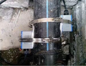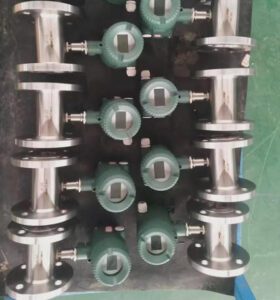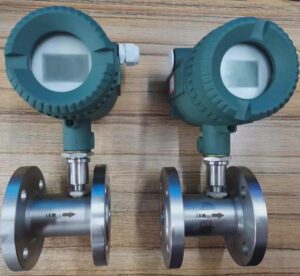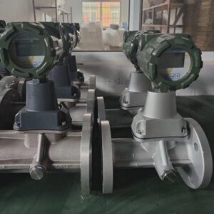
Flow measurement is rarely straightforward. The same pipeline that ran trouble-free for a decade can become a calibration headache after a process change — and the wrong meter choice can cost far more than the instrument itself. A refinery in northeastern China discovered this in 2023 when a batch of electronic ultrasonic meters, installed on high-pressure gas headers, required costly re-wiring and shielding after electromagnetic interference from nearby compressors degraded signal quality by over 18%. The engineering team switched to bourdon tube-based pressure measurement for the same headers and regained stable, repeatable readings — without a single additional electrical component.
That story illustrates the core premise of this guide: bourdon tube flow meters are not obsolete technology. They are a specific tool with a specific problem domain, and understanding that domain precisely is what separates an engineer who specifies the right instrument from one who replaces meters every two years.
This article walks through the fundamentals of how bourdon tube devices work, where they genuinely outperform alternatives, and — just as importantly — where they fall short. By the end, you will have a structured framework for deciding whether a bourdon tube device belongs on your pipe or whether a turbine, magnetic, Coriolis, or ultrasonic meter is the better fit.
Fundamentals of Bourdon Tube Flow Meters
Core Components and How a Bourdon Tube Converts Pressure into Displacement
The bourdon tube was invented by French engineer Eugène Bourdon in 1849. Ashcroft acquired the U.S. patent rights in 1852, which is why early American industry called these devices “Ashcroft Gauges.” The underlying physics has not changed since then — but the manufacturing precision, materials, and signal-conditioning electronics around them have advanced significantly.
At its core, a bourdon tube is a curved, hollow, flattened-cross-section tube sealed at one end and connected to the process at the other. When fluid pressure is applied to the open end, the tube’s cross-section tries to become more circular (a lower-energy shape), which causes the curved tube to partially straighten. That straightening motion — typically just a few millimetres of tip travel — is amplified by a mechanical linkage (sector gear, pinion, and pointer) to drive a dial indicator or electronic transducer. The higher the pressure, the more the tube straightens, and the higher the reading.
In flow measurement applications, the bourdon tube device does not directly measure flow rate. Instead, it measures differential pressure — the pressure drop across a known restriction (such as an orifice plate, venturi, or nozzle) in the pipe. Because that pressure drop is mathematically related to flow rate through the Bernoulli equation, the dial can be calibrated to display flow units directly. This is why bourdon-based flow meters are inherently differential-pressure (DP) instruments.
ρ = fluid density (kg/m³)
V₁ = upstream fluid velocity (m/s)
V₂ = velocity at the restriction throat (m/s)
Flow rate Q is then derived: Q = Cd × A₂ × √(2ΔP / ρ)
where Cd = discharge coefficient of the restriction element, A₂ = throat area
This relationship is the foundation of every bourdon tube-based flow reading. The device measures ΔP; the restriction geometry and fluid density do the rest of the calculation — either embedded in the dial calibration or fed into a downstream flow computer.
Typical Bourdon Tube Configurations and Their Implications
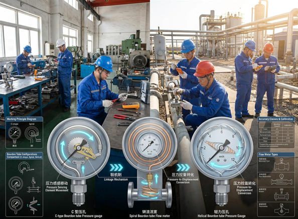
Three geometric configurations are available, each suited to a different pressure range and application. Selecting the wrong geometry is one of the most common early-stage specification errors.
| Configuration | Pressure Range | Tip Deflection | Sensitivity | Typical Applications | Cost Level |
|---|---|---|---|---|---|
| C-Type | 15 – 1,000 psi (1–70 bar) | ~4–5 mm | Moderate | HVAC, water supply, general process utilities | Low |
| Spiral | 0.6 – 40 bar (low to medium) | Up to 12 mm | High | Low-differential applications, oxygen service, laboratory equipment | Medium |
| Helical | 1,000 – 30,000 psi (70–2,000 bar) | Amplified via coils | High at extremes | Hydraulic systems, oil & gas wellheads, high-pressure research | High |
Common Fluid Types and Operating Ranges
Bourdon tube devices are compatible with a wide range of fluid types — but the tube material must be matched to the fluid’s chemical aggressiveness and temperature. Three material families cover the vast majority of industrial applications:
- Copper alloy (phosphor bronze): the standard material for non-corrosive liquids and gases — compressed air, water, steam up to 150 °C, and nitrogen. Cost-effective for general plant utilities.
- Stainless steel (316L): for mildly corrosive media — dilute acids, seawater, food-grade liquids, and applications requiring hygiene compliance. Required by many pharmaceutical and food processing standards.
- Monel, Hastelloy, or Inconel: for strongly corrosive media — concentrated chlorine, hydrofluoric acid, and high-temperature aggressive gases in petrochemical processing. Significantly more expensive but the only viable option in certain chemical environments.
Operating Principle and Signal Chain
Pressure-Induced Deflection to Flow Indication
The signal chain in a bourdon tube flow measurement system runs through four stages. Understanding each stage is essential for diagnosing where errors enter the measurement and how to correct them.
-
Pressure tap & restriction element. An orifice plate, venturi tube, or flow nozzle creates a predictable pressure drop (ΔP) proportional to the square of the flow velocity. The two pressure ports (upstream HP and downstream LP) are connected to the bourdon tube gauge via impulse lines — the same lines that can freeze, plug, or leak if not properly maintained.
-
Bourdon tube deflection. The differential pressure between HP and LP ports causes the tube to deflect. The deflection is proportional to ΔP within the tube’s elastic limit. Non-linearity begins above ~130% of full-scale pressure — one reason proper range selection matters enormously.
-
Mechanical amplification. A sector-gear and pinion mechanism amplifies the small tip movement (typically 3–12 mm) into a large pointer rotation (270° full scale). The gear ratio is fixed at manufacture — this is where span calibration errors originate if the gear geometry is imprecise or worn.
-
Readout & signal output. The pointer position on a calibrated dial provides local visual indication. Electronic versions add a Hall-effect sensor or potentiometer behind the pointer, generating a 4–20 mA signal for remote SCADA integration. Wireless models (such as the Bourdon WEP5 with LoRa radio) transmit readings over several kilometres without wiring.
Sensor Transduction Methods: Mechanical, Pneumatic, and Electronic
| Transduction Method | Output Type | Accuracy (Typical) | Power Required | Best Suited For |
|---|---|---|---|---|
| Mechanical (analog dial) | Visual local reading | ±1.0–3.0% FS | None | Local monitoring, hazardous areas, backup indication |
| Pneumatic (force-balance) | 3–15 psi air signal | ±0.5–1.0% FS | Instrument air supply | Legacy pneumatic DCS environments, intrinsically safe zones |
| Electronic (4–20 mA) | Analog + HART digital | ±0.1–0.5% FS | Loop power (24 VDC) | SCADA integration, data logging, alarm management |
| Wireless (LoRa/IoT) | Digital packet | ±0.25% FS (sensor) | Battery (3–10 year life) | Remote/unmanned sites, tank farms, pipelines without wiring |
Calibration Basics and Zero-Adjustment Considerations
A bourdon tube gauge requires two calibration adjustments: zero (setting the reading to zero at zero applied pressure) and span (ensuring full-scale deflection corresponds to the rated maximum pressure). Both are typically mechanical adjustments in analog units — a zero-adjustment screw moves the pointer independently, while span is set by adjusting the effective length of the sector gear arm.
Zero drift is the most common calibration issue in the field. A chemical plant in Shandong that participated in a 2024 instrumentation audit found that 34 out of 80 bourdon tube gauges had zero errors exceeding ±2% of full scale — all from mechanical relaxation and thermal cycling over a 24-month period without scheduled calibration. The fix was straightforward (a zero-adjustment on each gauge), but the undetected drift had introduced systematic bias into three months of process data used for yield calculations.
Typical Applications and Industries
Gas vs. Liquid Applications and Viscosity Considerations
Gas and liquid measurements using bourdon tube-based flow devices behave differently — not because the tube works differently, but because of how fluid properties affect the restriction element’s performance and the impulse line’s reliability.
For gas applications, the key considerations are compressibility corrections and condensation management. A compressed-air system at 6 bar has a gas density roughly 6× higher than atmospheric air. If the flow calculation uses atmospheric density, it will over-read volumetric flow by a factor of √6 ≈ 2.45 — a 145% error that has no relation to the meter’s inherent accuracy. Many plant engineers have made this mistake at startup. Bourdon-based flow systems for compressible gases must either include density compensation in the flow computer or use a fixed-density assumption appropriate for the nominal operating pressure.
For liquid applications, viscosity is the primary concern. The discharge coefficient (Cd) of an orifice plate or venturi — which is embedded in the flow calibration — is valid only within a specific Reynolds number range. When viscosity rises (e.g., lubricating oil cooling from 80 °C to 40 °C overnight), the Reynolds number drops, Cd shifts, and the bourdon-based flow indication becomes inaccurate. According to data from Turbines Incorporated, a 50% change in viscosity can cause 1–3% shifts in restriction-element-based flow readings.
Mid to High-Pressure Service Scenarios
Bourdon tube devices genuinely outperform many alternatives in mid-to-high-pressure service. Here is why:
At pressures above 150 bar, most electronic pressure transmitters face design challenges — specialized ceramics, welded diaphragms, or oil-filled systems become necessary, and costs rise steeply. A helical bourdon tube rated to 400 bar in stainless steel can be manufactured and calibrated for a fraction of that cost, with no electronic components that can fail from overvoltage, moisture ingress, or power interruption. A North Sea oil platform engineering team documented this trade-off explicitly: on wellhead pressure monitoring points where loss of power is a credible scenario, mechanical bourdon gauges are specified as the primary indication device — not because the electronic transmitters are inaccurate, but because the bourdon gauge works during power outages.
Remote Monitoring and Integration with Control Systems
The perception that bourdon tube devices are incompatible with modern digital infrastructure is outdated. Electronic bourdon gauges with 4–20 mA + HART outputs integrate seamlessly with any modern DCS or SCADA system. Wireless variants using LoRa radio (such as the Bourdon WEP5) transmit data to cloud-based monitoring platforms from distances exceeding 2 km, with battery lives of up to 10 years — eliminating cable infrastructure costs on remote measurement points.
A gas distribution company in Inner Mongolia fitted 42 remote pressure taps with wireless electronic bourdon transmitters in 2023, replacing manual gauge-reading rounds that consumed 3 technician-days per week. The wireless system paid back its installation cost in under 14 months purely through labour savings.
Watch: How a Bourdon Tube Pressure Gauge Works
Video: “Bourdon Tube Pressure Gauge Working Animation” — covers the construction, operating principle, and signal chain of a bourdon tube gauge in a clear animated format suitable for engineers and technicians.
Fluids, Ranges, and Environmental Considerations
Temperature Effects and Material Compatibility
Temperature affects bourdon tube accuracy in two independent ways: it changes the elastic modulus of the tube material (causing span drift), and it changes the process fluid’s density (introducing flow calculation errors). Both effects compound if not addressed.
The elastic modulus of phosphor bronze decreases by approximately 0.05% per °C. A gauge calibrated at 20 °C operating at 80 °C will have a span that is about 3% low — meaning the actual pressure is 3% higher than the reading. For stainless steel 316L, the effect is smaller (≈0.03%/°C), which is one reason stainless is preferred for high-temperature service even when corrosion resistance is not the primary concern. Liquid-filled gauges (glycerin or silicone oil fill) damp temperature-induced mechanical noise effectively, but they have their own limitation: the fill liquid expands with temperature and can create a false zero offset at elevated ambient temperatures.
| Tube Material | Max Process Temp | Compatible Fluids | Corrosion Notes | Typical Application |
|---|---|---|---|---|
| Phosphor Bronze (Cu alloy) | 150 °C | Air, water, steam, N₂, non-corrosive gases | Not suitable for ammonia or amines (stress corrosion) | HVAC, plant utilities, water treatment |
| Stainless Steel 316L | 300 °C | Dilute acids, seawater, food-grade liquids, chlorine-free chemicals | Avoid concentrated chloride environments | Chemical, pharmaceutical, food & beverage |
| Monel 400 | 400 °C | Hydrofluoric acid, seawater, reducing acids | Good HF resistance; avoid oxidising acids | Petrochemical, offshore |
| Hastelloy C-276 | 500 °C | Chlorine, FeCl₃, mixed acid environments | Broadest corrosion resistance; highest cost | Chemical plant, waste-gas treatment |
Pressure and Flow Range Selections for Bourdon Meters
A commonly overlooked specification rule: the working pressure should fall between 25% and 75% of the gauge’s full-scale range for continuous service (ASME B40.1). Operating continuously at 90% of full scale causes accelerated fatigue — the tube’s metal experiences more extreme cyclic stress — and will shorten gauge life below the 1 million cycle ASME minimum. Operating at 10% of full scale wastes resolution and degrades readability and accuracy.
For flow applications where ΔP may range from near-zero to full-scale during startup and shutdown, a maximum-working-pressure selector valve or snubber (a restriction fitting that dampens pressure spikes) is strongly recommended to protect the tube during transient conditions.
Environmental and Installation Constraints
Three environmental factors consistently shorten bourdon gauge service life when not accounted for at the design stage:
- Vibration: mechanical vibration from pumps, compressors, or fans causes the pointer to oscillate and accelerates gear wear. The solution is a liquid-filled gauge (the fill dampens internal motion) or a remote-seal installation that moves the gauge away from the vibration source.
- Pulsation: reciprocating pumps create pressure pulses that can drive the tube into its non-linear range repeatedly. A pulsation snubber (typically a sintered stainless disc or adjustable needle valve) installed in the connection port reduces pulse amplitude without significantly affecting the steady-state reading.
- Ambient temperature extremes: below −20 °C, glycerin fill becomes viscous enough to impair pointer movement. Silicone-oil-filled gauges operate to −60 °C. Above 60 °C ambient, liquid-fill expansion can shift zero. In these environments, dry-fill gauges with bourdon tubes selected for thermal stability are preferable.
Accuracy, Calibration, and Maintenance
Factors Influencing Measurement Accuracy
Bourdon tube flow accuracy is not a single number — it is the product of three compounding error sources, each of which must be understood and managed independently.
Analysis derived from calibration audit data across chemical, water treatment, and HVAC installations. The restriction element’s discharge coefficient variation — driven by orifice edge wear, Reynolds number shifts, and upstream disturbance — is the largest single source of error in bourdon-based flow systems.
Calibration Frequency and Techniques
The standard calibration procedure for a bourdon tube gauge involves applying known reference pressures from a dead-weight tester or calibrated electronic reference transmitter, recording the gauge reading at five equidistant points across the range (upscale and downscale), and calculating zero error, span error, and hysteresis. According to Blanes Pressure Solutions’ calibration guide, acceptable hysteresis (the difference between upscale and downscale readings at the same pressure) should not exceed 0.3–0.5% of full scale for Grade A gauges.
For critical flow measurement applications, annual calibration is the minimum. A natural gas utility in Liaoning Province adopted a 6-month calibration cycle on 22 bourdon-based orifice flow stations after discovering that 31% of units exceeded ±2% span error at the 12-month check — far exceeding their ±1% process requirement. Shortening the cycle to 6 months brought the out-of-tolerance rate down to 8%.
Maintenance Practices and Common Failure Modes
| Failure Mode | Root Cause | Detection Method | Corrective Action |
|---|---|---|---|
| Zero drift (pointer rests above zero) | Elastic deformation of tube from sustained overpressure or thermal cycling | Visual check with process isolated | Zero-adjustment screw; replace tube if drift exceeds 3% FS |
| Sticky pointer | Worn gear teeth, dirty mechanism, or crystallised process fluid in tube | Tap gauge housing; watch for pointer jump | Clean mechanism; replace gears; flush and purge tube |
| Cracked bourdon tube | Fatigue (pulsation), corrosion, or overpressure beyond 130% FS | Gauge reads zero or leaks process fluid | Replace gauge immediately; investigate root cause; add snubber |
| Reading frozen at last value | Plugged impulse line (crystallising media, wax, or ice) | Gauge reading does not respond to known flow change | Clear impulse line; add heat tracing or chemical inhibitor |
| Oscillating / jumpy reading | Pulsating flow from pump; mechanical vibration | Visible pointer oscillation | Add snubber; switch to liquid-filled gauge |
| Span drift (reading low or high at full scale) | Worn sector gear; temperature effects on elastic modulus | Calibration check against reference | Adjust gear arm length; recalibrate; replace if mechanism worn |
Advantages of Bourdon-Based Flow Meters
Simplicity, Ruggedness, and Reliability
A standard C-type bourdon gauge has fewer than 15 components. There are no circuit boards, no firmware to update, no batteries to replace, and no network connectivity to troubleshoot. When a gauge fails in a remote ammonia refrigeration plant in northwestern China, the maintenance technician carries a replacement in their pocket — not a laptop and a specialist calibration kit. This simplicity translates directly into mean-time-to-repair (MTTR) figures that electronic systems cannot match in field conditions.
ASME B40.1 requires that a high-quality bourdon tube withstand at least 1 million pressure cycles before structural failure. In many moderate-pressure applications, that translates to a service life of 10–20 years before major components need replacement.
No Moving Parts in Some Designs and Low Maintenance
The bourdon tube itself has no moving parts — only the mechanical linkage (sector gear, pinion, and pointer) introduces wear components. In some modern designs, the linkage is replaced by a Hall-effect sensor that reads the tip position magnetically, eliminating the gear mechanism entirely and reducing the mechanical wear surface to effectively zero. These designs retain the bourdon tube’s power-independence and pressure range advantages while significantly improving long-term stability.
Cost Considerations Over Lifecycle
A high-quality WIKA 232.50 stainless steel bourdon gauge retails at approximately $80–$180 depending on range and connection. An equivalent Endress+Hauser electronic pressure transmitter for the same service starts at $350–$800 before commissioning costs. For a large plant with 200 pressure monitoring points, the capital difference is $54,000–$124,000 — before accounting for the wiring, junction boxes, and instrument power supply infrastructure that the electronic transmitters require and the mechanical gauges do not.
Where the economics reverse is in large-scale data integration and alarm management, where the cost of manual gauge rounds is higher than the infrastructure cost of electronic transmitters. The crossover point depends on site size, staffing costs, and data requirements — a structured lifecycle cost model, such as the one available through Jade Ant Instruments’ 5-factor flow meter selection guide, can quantify this trade-off for a specific plant scenario.
Limitations and Caveats
Lower Dynamic Response Compared to Modern Meters
The mechanical linkage in a bourdon gauge has inertia. The sector gear, pinion, and pointer cannot respond to pressure changes faster than approximately 0.5–2 seconds. For steady-state monitoring of slowly varying flows (steam distribution headers, cooling water loops, HVAC circuits), this response time is invisible — the process changes more slowly than the meter can detect. For fast-response applications — batch filling, surge detection, reciprocating compressor monitoring — the bourdon tube’s lag can miss critical events entirely. In those cases, electronic pressure transmitters with response times of 50–200 milliseconds are the correct choice.
Potential for Mechanical Drift and Hysteresis
Every mechanical element has hysteresis — the property that causes the output at a given input to differ depending on whether you arrived at that input from above or below. In bourdon tubes, hysteresis arises from two sources: elastic hysteresis in the tube metal itself (typically 0.1–0.3% FS for high-quality tubes) and friction in the gear-linkage mechanism (0.1–0.5% FS for well-maintained mechanisms). Combined, this means a well-calibrated bourdon gauge will show approximately 0.2–0.8% FS uncertainty due to hysteresis alone — before adding scale-reading error and impulse-line effects.
In flow measurement terms, where the bourdon tube reads ΔP and flow is proportional to √ΔP, hysteresis in the ΔP reading gets amplified. A 1% ΔP error at 25% of full-scale ΔP translates to approximately 2% flow error due to the square-root relationship. Engineers specifying bourdon-based flow systems need to account for this amplification when evaluating whether ±2–3% flow accuracy is acceptable for their application.
Suitability Mainly for Steady or Slowly Varying Flows
The combination of mechanical inertia, hysteresis, and the square-root relationship between ΔP and flow means that bourdon-based flow meters are fundamentally better suited to monitoring rather than controlling fast-moving processes. They are reliable sentinels for steady-state conditions; they are poor substitutes for fast-response electronic sensors in closed-loop control systems where the controller acts on flow changes within seconds.
Installation, Integration, and Best Practices
Piping Layout, Mounting Orientation, and Vibration Considerations
Signal Integration with Control Systems and Data Logging
For plants moving toward digital infrastructure, the path from a mechanical bourdon gauge to a SCADA data point has several options, in increasing order of cost and integration depth:
- Add an electronic output module to an existing mechanical gauge (≈$50–$150 retrofit kit; outputs 4–20 mA) — lowest cost, limited accuracy improvement
- Replace with a combination electronic/mechanical gauge (bourdon tube + Hall-effect sensor, local dial + 4–20 mA) — retains local readability while enabling remote data
- Install a standalone electronic pressure transmitter on the same tap as the mechanical gauge — the gauge serves as a visual backup; the transmitter handles SCADA
- Deploy wireless electronic bourdon transmitters (LoRa, WirelessHART) for locations where wiring is impractical
When specifying 4–20 mA output from a bourdon-based transmitter for SCADA integration, verify that the DCS input card supports HART communication — this enables remote configuration, multi-variable output (process value, loop current, device diagnostics), and alarms without additional wiring. For plants standardised on Modbus RTU, specify a transmitter with RS-485 output and a documented register map.
Protection, Seals, and Maintenance Access
Three protective measures consistently extend gauge service life in aggressive environments:
- Chemical seals (diaphragm seals): a flexible metal diaphragm is welded to the process connection, with a capillary tube filled with an inert fluid (silicone oil) connecting to the gauge. The process fluid never contacts the bourdon tube — critical for corrosive media, slurries, or crystallising fluids that would destroy a direct-coupled gauge within months.
- Syphons (pigtail syphons): a coiled or U-shaped tube between the steam line and the gauge that remains filled with cool condensate, preventing hot steam from directly entering and overheating the bourdon tube. Required for steam service above 150 °C.
- Root valves and manifolds: a two- or three-valve manifold at the pressure tap allows the gauge to be isolated for calibration and maintenance without shutting down the process. Without isolation valves, every calibration check requires a process shutdown — a constraint that many plants use to justify skipping calibration altogether.
When to Choose Bourdon vs. Other Flowmeters
Decision Criteria: Accuracy Needs, Response Time, and Process Conditions
Illustrative 10-year TCO based on field cost data from chemical and utility plant records (2022–2025). The bourdon DP system’s low TCO advantage depends on a ±2–3% flow accuracy being acceptable. Where ±0.5% is required, Coriolis or vortex meters are more appropriate despite higher lifetime cost.
Comparative Summary with Turbine, Magnetic, Coriolis, and Ultrasonic Meters
| Criterion | Bourdon DP | Turbine | Magnetic | Coriolis | Ultrasonic |
|---|---|---|---|---|---|
| Accuracy (flow) | ±1–3% | ±0.25–0.5% | ±0.2–0.5% | ±0.05–0.1% | ±0.5–1.5% |
| Power required | None (mechanical) | Yes (pulse counter) | Yes (excitation coil) | Yes (electronics) | Yes (transducers) |
| Gas / steam service | Yes | Gas turbine only | No (non-conductive) | Yes | Yes |
| Liquid (conductive) | Yes | Yes (clean only) | Yes (best option) | Yes | Yes |
| Slurry / viscous fluids | No | No (bearing damage) | Yes (best option) | Limited | No (signal loss) |
| Dynamic response | Slow (0.5–2 s) | Fast (ms) | Fast (ms) | Fast (ms) | Fast (ms) |
| High pressure (>150 bar) | Excellent (helical) | Possible (special) | Limited | Possible | Limited |
| Straight-pipe run needed | 10–20D (orifice plate) | 10–15D | 5D | None | 15–20D |
| Typical CAPEX (DN50) | $500–$1,500 | $800–$3,000 | $800–$4,000 | $4,000–$14,000 | $800–$5,000 |
| 10-Year TCO | $9,800 (est.) | $17,500 | $10,100 | $22,000 | $13,000 |
| Bidirectional flow | No | No (standard) | Yes | Yes | Yes |
Sources: Engineering ToolBox flowmeter comparison; manufacturer datasheets; field cost records (2024–2025). See also Jade Ant Instruments’ flow meter manufacturer comparison.
Practical Decision Workflow for Retrofits and New Installations
Bourdon tube flow measurement occupies a specific and genuinely valuable niche in the industrial instrumentation landscape — one that is often either underestimated or overextended by engineers who do not map the technology to the problem carefully.
The core decision factors, stripped to essentials, are these:
- Accuracy requirement of ±1–3%: bourdon-based DP systems are appropriate and cost-effective. Below ±1%, specify turbine, Coriolis, or vortex.
- No electrical power available: the mechanical bourdon gauge is the default — there is simply no alternative that works without power in a hazardous area.
- High-pressure service (>150 bar): helical bourdon designs handle pressures that most electronic transmitters cannot reach economically.
- Clean, single-phase, moderate-viscosity fluid: the sweet spot for bourdon-based restriction-element flow measurement.
- Slowly varying flow: bourdon gauges are excellent monitors; they are poor substitutes for fast-response sensors in dynamic control loops.
Common Myths vs. Realities
| Myth | Reality |
|---|---|
| “Bourdon gauges are obsolete — use electronic transmitters for everything.” | For remote unmanned locations, high-pressure service, and hazardous areas without wiring infrastructure, mechanical bourdon gauges remain the most reliable and cost-effective option. |
| “They’re maintenance-free.” | Annual calibration checks are essential. A Shandong audit found 42% of gauges with zero drift exceeding ±2% FS after 24 months without calibration. |
| “They can’t integrate with digital systems.” | Electronic bourdon transmitters with 4–20 mA, HART, Modbus, and wireless LoRa outputs are commercially available from multiple manufacturers. |
| “Any fluid works if you pick the right material.” | Highly viscous (>80 cP), crystallising, or slurry fluids will degrade accuracy or damage the tube regardless of material selection. Use a diaphragm seal or different meter technology. |
Quick-Start Checklist for Practitioners
- Confirm fluid viscosity is below 80 cP and the fluid is single-phase at operating conditions
- Select tube material compatible with the fluid’s chemistry and temperature (phosphor bronze, SS316L, Monel, or Hastelloy)
- Size the gauge range so the normal operating pressure falls between 25% and 75% of full scale
- Choose configuration: C-type (15–1,000 psi), spiral (low-pressure, high sensitivity), or helical (>1,000 psi)
- Install syphon for steam >150 °C; add snubber for pulsating service; add chemical seal for corrosive or crystallising media
- Mount above pipe for gas; below pipe for liquid (to manage impulse line fluid column)
- Specify isolation valves on both pressure taps for in-service calibration
- Schedule calibration: annually for clean service, every 6 months for pulsating or temperature-cycling applications
- If SCADA integration is required, add electronic 4–20 mA + HART module or replace with combination gauge-transmitter
Glossary of Key Terms
Need Help Specifying the Right Flow Measurement Device?
Jade Ant Instruments provides free engineering consultation — including fluid compatibility assessment, tube material selection, accuracy modelling, and integration guidance for bourdon-based and electronic flow metering systems. ISO 9001 certified. Ships to 50+ countries.
Request Free Consultation & Quote →Frequently Asked Questions
Published by Jade Ant Instruments — ISO 9001 Certified Flow Meter Manufacturer | Electromagnetic, Vortex, Turbine, Ultrasonic Flow Meters | Ships to 50+ Countries
Related reading:
5 Factors for Choosing a Flow Meter ·
Variable Area Flow Meter Selection Guide ·
Electromagnetic Flow Meter Selection Guide ·
High vs. Low Pressure Flow Meters ·
How to Read Flowmeter Datasheets