Vortex Flow Meter for Steam & Gas: Complete Engineer’s Guide
Working principle, sensor technology, accuracy data, installation requirements, TCO comparison, and a brand-by-brand spec table — everything you need to specify a vortex meter correctly.
Picture a refinery engineer reviewing last quarter’s utility bills. Steam costs are 12 % above budget. The culprit, after investigation, is not a boiler fault — it is an orifice plate flow meter on a saturated-steam header that has been over-reading by 9 % because the impulse lines picked up condensation and the orifice edge has eroded after five years of service. The fix: replace three orifice plates with vortex flow meters. Result: billing accuracy restored, impulse-line maintenance eliminated, and permanent pressure drop on that header cut by 62 %.
That scenario plays out in power plants, chemical facilities, food-processing plants, and HVAC systems worldwide. The vortex flow meter — measuring liquid, gas, and steam with a single fixed bluff body and no moving parts — has become the default upgrade path from legacy differential-pressure (DP) instrumentation wherever the fluid is hot, variable, or expensive enough to count. This guide explains exactly how vortex meters work, where they outperform alternatives, and what you need to specify them correctly.
How a Vortex Flow Meter Works
The physics behind every vortex flow meter is the von Kármán vortex street — a phenomenon first mathematically described by Theodore von Kármán in 1911. When fluid flows past a non-streamlined object (called a bluff body or shedder bar), it cannot smoothly re-attach behind the obstacle. Instead, alternating vortices — rotating columns of fluid — peel off from each side of the bluff body in a stable, repeating pattern. These vortices trail downstream like a street of staggered eddies, which is where the name comes from.
The critical insight is that the frequency at which vortices shed is directly proportional to fluid velocity. That relationship, known as the Strouhal equation, is the heart of every vortex meter’s signal chain:
The Strouhal Equation — Converting Frequency to Flow Rate
St = Strouhal number (dimensionless constant, typically 0.20–0.28 for industrial bluff bodies)
V = mean fluid velocity (m/s)
d = bluff body width (m)
K = meter K-factor (pulses per m³) — unique to each meter, determined during factory calibration per ISO 12764
The Strouhal number (St) remains essentially constant for a given bluff body geometry across a wide Reynolds number range — typically Re 10,000 to 7,000,000 (research from ScienceDirect confirms stable vortex formation down to Re ≈ 6,500 under controlled conditions). This constancy means the meter’s calibration K-factor does not change with fluid temperature, pressure, density, or viscosity — as long as the Reynolds number stays above the minimum threshold. That is why a single vortex meter sized for steam at 200 °C will measure the same pipe section accurately after a plant startup on cold compressed air at 15 °C, without recalibration.
Sensor Technology Inside a Vortex Meter
Three sensor types are used to detect vortex-induced pressure fluctuations. Each has distinct advantages depending on the process conditions:
| Sensor Type | Detection Method | Best For | Limitations | Typical Brands |
|---|---|---|---|---|
| Piezoelectric | Crystal generates voltage when deformed by pressure pulse from vortex | Steam, hot gas, high-temperature liquids up to 450 °C | Sensitive to mechanical pipe vibration (false signals at low flow) | Emerson Rosemount, Yokogawa, Jade Ant Instruments |
| Capacitive | Flexible diaphragm changes capacitance in response to differential pressure from vortex | Low-to-medium temperature liquids and gases; vibration-prone locations | More complex electronics; slightly higher cost; temperature ceiling ~250 °C | Endress+Hauser Prowirl, KROHNE OPTISWIRL |
| Thermal (hot-wire) | Vortex-induced velocity fluctuations cool a heated element; temperature change is measured | Very low flow rates, clean gases, laboratory applications | Not suitable for liquids or steam; fragile sensor wire; limited to clean fluids | Endress+Hauser (select models) |
Steam Measurement: Where Vortex Meters Shine
Steam is the most challenging industrial fluid to measure accurately. Its density changes by more than 300% across typical operating pressure ranges (1–15 bar). Entrained moisture in saturated steam causes orifice plates to over-read by 8–12%. And impulse lines connecting DP instruments to steam headers freeze in winter, plug with condensate, and leak at ferrule fittings — creating maintenance burdens that far exceed the initial cost savings of choosing a cheaper DP instrument.
Vortex meters address every one of these challenges:
Saturated vs. Superheated Steam: What Changes?
Saturated steam exists at the boiling point for a given pressure — any heat removal causes condensation. Superheated steam is heated beyond the boiling point, so it can absorb heat without condensing. From a vortex meter’s perspective, the physics of vortex shedding works identically for both phases. The critical difference is density calculation. A multivariable vortex meter with integrated RTD (temperature) and pressure transmitter uses the IAPWS-IF97 steam tables — the international standard steam property database — to calculate real-time density, enabling accurate mass flow output regardless of which phase the meter is measuring.
Case Study: Boiler House Retrofit, Guangdong Province
A textile finishing plant in Guangdong replaced six DP orifice plates on boiler-steam headers with multivariable vortex meters from Jade Ant Instruments. Before the retrofit, the plant was reconciling a 7.3% gap between boiler steam-generation readings and process consumption readings — attributed to orifice-plate measurement drift and impulse-line condensation errors. After the retrofit:
- Measurement gap closed to 1.1% — within normal heat-loss expectations for an insulated system.
- Impulse-line maintenance eliminated — previously 11 service calls per year, now zero.
- Energy audit passed first time under ISO 50001 requirements, enabling preferential electricity tariff.
- Annual steam cost reduction: ¥280,000 ($38,500 USD) through billing accuracy correction alone.
Vortex vs. Alternative Flow Meter Technologies
| Parameter | Vortex | DP Orifice Plate | Turbine | Electromagnetic | Coriolis |
|---|---|---|---|---|---|
| Measurement Principle | Vortex shedding frequency | Bernoulli pressure differential | Rotor rotation speed | Faraday’s law (EMF) | Coriolis force phase shift |
| Accuracy (Liquid) | ±0.75–1.0% | ±1.0–2.0% | ±0.25–0.5% | ±0.2–0.5% | ±0.05–0.1% |
| Accuracy (Gas/Steam) | ±1.0–1.5% | ±1.5–2.5% | ±0.5–1.0% (gas turbine only) | N/A | ±0.35% (high-pressure gas) |
| Moving Parts | None | None | Yes (rotor + bearings) | None | None |
| Turndown Ratio | 10:1 (liquid) / 20–30:1 (gas) | 3:1 to 5:1 | 10:1 to 30:1 | Up to 1000:1 | 80:1 to 100:1 |
| Permanent Pressure Drop | Low (0.3–1.0 bar) | High (1.5–4.0 bar) | Medium (0.5–1.5 bar) | Zero (full bore) | Medium (0.3–1.5 bar) |
| Steam Measurement | Excellent | Limited | Not suitable | Not suitable | Yes (high cost) |
| Max. Temperature | Up to 450 °C | Any (remote seal) | Up to 250 °C | Up to 180 °C (standard) | Up to 400 °C |
| Straight Run Required | 15–25D upstream, 5D down | 10–20D upstream, 5D down | 10–15D upstream, 5D down | 5D upstream, 2–3D down | None |
| Typical CAPEX (DN50–100) | $1,000–$3,000 | $800–$2,500 | $800–$3,000 | $800–$4,000 | $4,000–$14,000 |
| 10-Year TCO (DN50, steam/gas) | $8,500–$14,000 | $28,000–$42,000 | $13,000–$22,000 | $8,000–$12,000 (liquid only) | $16,000–$28,000 |
| Impulse Lines Required | No | Yes — freeze/plug risk | No | No | No |
Sources: Emerson, Endress+Hauser, KROHNE, Jade Ant Instruments published datasheets; 10-year TCO derived from field-documented maintenance costs (2024–2026).
Performance Data: Charts & Visuals
10-Year Total Cost of Ownership — By Technology (DN50 Gas/Steam Line)
Sources: Emerson case study (refinery retrofit), Turbines Inc. maintenance cost data, Jade Ant Instruments field reports (2024–2026). TCO includes CAPEX, calibration, maintenance labour, pressure-loss energy, and unplanned downtime allowance.
Root Causes of Vortex Meter Field Failures
Installation Best Practices
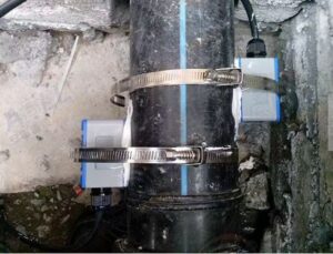
The single largest cause of vortex meter field failures — 28% according to service-record analysis — is insufficient upstream straight-pipe length. The bluff body can only shed coherent, countable vortices if the flow velocity profile entering the meter is fully developed and symmetric. Elbows, valves, reducers, and tee junctions all distort this profile for many pipe diameters downstream.
| Upstream Disturbance | Min. Upstream Straight Run | Min. Downstream | Notes |
|---|---|---|---|
| Single elbow (same plane) | 15D | 5D | Standard specification — most installations |
| Two elbows (different planes) | 25D | 5D | Out-of-plane elbows cause swirl; most problematic disturbance |
| Reducer (2:1 contraction) | 20D | 5D | Asymmetric velocity profile from flow acceleration |
| Globe valve or control valve (≥50% open) | 20–40D | 5D | Throttled valves create severe turbulence; consider flow conditioner |
| Pump discharge | 30D | 5D | Pulsating flow from reciprocating pumps may require pulsation dampener |
| T-junction / branch | 25D | 5D | Measure on the main run, not the branch |
Source: Zero Instrument installation guide; IFM vortex selection guide; manufacturer data for Emerson Rosemount 8800D and Endress+Hauser Prowirl F 200.
Top Vortex Flow Meter Brands: Spec-by-Spec Comparison
Five manufacturers dominate the industrial vortex flow meter market, each with a distinct technology philosophy and application strength. The table below compares their flagship models on the specifications that matter most to plant engineers:
| Brand / Model | Accuracy (Liquid) | Max Temp. | Max Press. | DN Range | Standout Feature | Protocols | Price Range (USD) |
|---|---|---|---|---|---|---|---|
| Emerson Rosemount 8800D | ±0.65% (liquid) ±1.35% (gas/steam) |
427 °C | 200 bar | DN15–DN300 | Adaptive Digital Signal Processing (ADSP) filters pipe vibration; Reducer Vortex variant | HART, Foundation Fieldbus, WirelessHART | $2,500–$6,500 |
| Yokogawa digitalYEWFLO | ±0.75% (liquid) | 450 °C | 200 bar | DN15–DN400 | Spectral Signal Processing (SSP) + dual piezoelectric elements; self-diagnostics per NAMUR NE107 | HART, PROFIBUS PA, Foundation Fieldbus | $2,200–$5,800 |
| Endress+Hauser Prowirl F 200 | ±0.75% (liquid) | 400 °C | 160 bar | DN15–DN300 | Heartbeat Technology (in-situ verification without process interruption); SIL 2 certified; integrated T/P sensors | HART, Modbus, PROFIBUS PA, EtherNet/IP | $2,800–$7,000 |
| KROHNE OPTISWIRL 4200 | ±0.75% (liquid) | 400 °C | 100 bar | DN15–DN300 | Wet-steam detection via spectral signal analysis; handles lowest flow rates in category; fully welded design | HART, PROFIBUS PA, Modbus | $2,600–$6,200 |
| Jade Ant Instruments | ±1.0% (liquid) ±1.5% (gas/steam) |
350 °C (standard) 400 °C (HT model) |
40 bar (standard) 60 bar (HT) |
DN15–DN300 | ISO 9001 manufacturing; PTFE/SS wetted parts; integrated T/P compensation on multivariable model; cost-effective for process control (non-custody) | 4–20 mA, HART, Modbus RS-485, pulse | $800–$2,200 |
Sources: BCST Group top-5 vortex brands guide; manufacturer datasheets; Jade Ant Instruments product documentation. Prices are indicative 2026 list prices for DN50–DN100 standard flanged versions.
Watch: How a Vortex Flow Meter Works
Video: “Comparing Turbine and Vortex Flowmeters” — a concise engineering walkthrough of the vortex shedding principle, K-factor calibration, and real installation scenarios. (Source: YouTube)
7-Step Vortex Flow Meter Selection Guide
Selecting a vortex meter correctly requires working through seven sequential decision checkpoints. Skip any one of them and you risk specifying a meter that cannot achieve its stated accuracy in your specific installation:
-
Identify the fluid and its properties. Confirm the fluid phase (liquid, gas, steam), operating temperature (°C), pressure (bar), and viscosity (cP). For steam, determine whether it is saturated or superheated and obtain the pressure range. Viscosities above ~30 cP suppress vortex shedding — switch to Coriolis or positive-displacement meters for viscous fluids.
-
Calculate the Reynolds number at minimum flow. Use Re = (ρ × V × D) / μ where ρ is fluid density, V is velocity, D is pipe internal diameter, and μ is dynamic viscosity. The meter must achieve Re ≥ 10,000 at the minimum expected flow rate. If it cannot, either reduce the meter bore (to increase velocity) or choose a different technology. The IFM vortex selection guide includes an interactive Reynolds number calculator.
-
Size the meter bore for the correct velocity range. Vortex meters work best between 0.3–9 m/s (liquids) and 4–80 m/s (gas/steam). Do not simply match the meter bore to the pipe bore — many installations require a reduced-bore meter to keep velocities within the optimal shedding range, particularly on large-diameter gas lines with wide flow variability.
-
Audit the available straight-pipe run. Walk the installation and measure the actual distance from the nearest upstream disturbance (elbow, valve, reducer) to the proposed meter location. If the distance is less than 15D, plan for a flow conditioner or relocate the meter. Document your findings — installation photos help resolve disputes later if accuracy is questioned.
-
Select materials and pressure rating. Wetted parts (bluff body, meter body, sensor housing) must be compatible with the fluid’s chemical composition and temperature. Stainless steel (316L) covers the majority of applications; Hastelloy C-276 is required for chloride-rich or highly corrosive fluids. Confirm that the meter’s pressure rating (ANSI Class or PN rating) exceeds the process’s maximum allowable working pressure with at least 25% safety margin.
-
Specify output and communication protocol. At minimum, require 4–20 mA + pulse output. For DCS integration, add HART. For Modbus-based SCADA or PLC systems, confirm Modbus RTU/TCP with a documented register map. For energy-monitoring under ISO 50001, a multivariable model with integrated temperature and pressure compensation outputs mass flow and thermal energy directly — eliminating the need for a separate flow computer.
-
Build a 10-year TCO model before comparing prices. Request the vendor’s estimated calibration interval, annual maintenance cost, and spare-parts pricing. Add permanent-pressure-drop energy cost (calculate from the meter’s published pressure loss at operating flow rate). Compare the total against alternative technologies. A meter that costs $500 more at purchase but saves $2,000/year in maintenance and energy pays back in 4 months.
Vortex Flow Meter Application Matrix
| Industry | Fluid | Suitability | Key Configuration | Consider Instead |
|---|---|---|---|---|
| Power generation | Superheated steam (12–40 bar) | Excellent | Multivariable with T/P compensation; DN50–DN200 | DP averaging pitot for >DN300 |
| District heating | Saturated steam, hot water (<180 °C) | Excellent | Energy-meter output (GJ/h); integrated RTD | Electromagnetic for hot water below 180 °C |
| Chemical processing | Compressed N₂, CO₂, natural gas | Excellent | Stainless or Hastelloy body; HART output to DCS | Coriolis for custody transfer of gas |
| HVAC / Building | Chilled water, heating water | Good (verify Re) | Confirm velocity >0.5 m/s at minimum load; low pressure-drop body | Electromagnetic if low-flow periods are common |
| Food & beverage | Clean process water, steam (CIP) | Good | 3A/EHEDG-compliant hygienic version; steam-rated for CIP cycles | Electromagnetic for product lines |
| Oil & gas upstream | Natural gas, flare gas | Good | Explosion-proof (ATEX/IECEx) housing; pulse output to flow computer | Ultrasonic for custody-transfer-grade accuracy |
| Mining | Slurry, tailings water | Not Suitable | — | Electromagnetic (rubber-lined) |
| Pharmaceutical | High-purity water, clean steam | Conditional | Sanitary connections (Tri-Clamp); electropolished SS316L; crevice-free design | Coriolis for WFI and precise dosing |
Glossary of Key Terms
Need Help Sizing a Vortex Flow Meter for Your Application?
Jade Ant Instruments provides free engineering consultation — including Reynolds number verification, bore sizing, straight-run assessment, and material selection — for steam, gas, compressed air, HVAC, and chemical applications. ISO 9001 certified. Ships to 50+ countries.
Request Free Sizing & Quote →Frequently Asked Questions
Published by Jade Ant Instruments — ISO 9001 Certified Flow Meter Manufacturer | Electromagnetic, Vortex, Turbine, Ultrasonic Flow Meters | Ships to 50+ Countries
Related reading:
5 Factors for Choosing a Flow Meter ·
Vortex vs. Turbine Flow Meter Comparison ·
Liquid Flow Measurement Principles Compared ·
How to Choose a Flow Meter Supplier