
A flow meter that reads 100 L/min when the true flow is 95 L/min may seem like a minor discrepancy — until you scale it across 8,760 operating hours per year. At a chemical dosing station, that 5 % error compounds into 26,280 litres of over-dosed reagent annually, translating to roughly US $20,000–$40,000 in wasted chemicals according to Fox Thermal Instruments’ 2026 field data. Calibration is the only defence against this invisible cost leak.
This guide, compiled with technical input from Jade Ant Instruments — an ISO-certified flow meter manufacturer — walks you through every step of flow meter sensor calibration: from choosing the right method and assembling tools, through the zero-check and span-adjustment procedure, to setting calibration intervals and avoiding the seven most common mistakes.
1. Why Calibration Matters — With Real Numbers
Flow meter sensors are exposed to vibration, temperature cycling, chemical attack, and electrode fouling — all of which cause measurement drift. According to the Endress+Hauser calibration management white paper, even well-maintained electromagnetic meters can drift 0.1–0.3 % per year, while turbine meters with worn bearings may drift 1–2 % annually. For a plant processing 500 m³/day of treated water billed at US $1.50/m³, a 2 % under-reading means a revenue loss of US $5,475 every year — silent, cumulative, and entirely preventable.
Calibration also protects regulatory compliance. ISO 17025 and NIST traceability frameworks require that calibration reference standards be at least four times more accurate than the device under test. Custody-transfer applications in oil and gas mandate traceable calibration per API MPMS Chapter 4. Missing these intervals risks audit failures, fines, or rejected shipments.

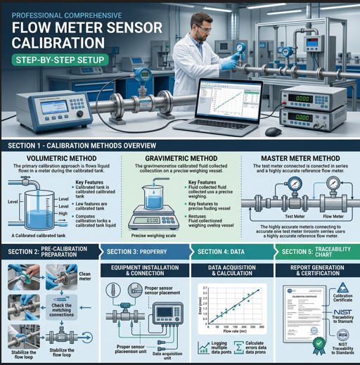
2. Three Calibration Methods Compared
Every calibration comes down to one question: How do I generate a known reference flow to compare against my meter’s reading? The three primary approaches — gravimetric, volumetric, and master-meter — each answer that question differently. The table below, formatted for direct paste into Excel, summarises their key attributes.
Excel-Ready Comparison Table — Calibration Methods
| Parameter | Gravimetric (Weighing) | Volumetric (Tank) | Master-Meter (Transfer) |
|---|---|---|---|
| Principle | Collect fluid in a weigh tank; calculate mass flow from weight ÷ time | Fill a calibrated volume vessel; measure time to fill | Install a high-accuracy reference meter in series; compare readings |
| Reference Uncertainty | ±0.02–0.05 % (best-in-class labs) | ±0.05–0.2 % | ±0.15–0.5 % (depends on master meter class) |
| Typical Location | Accredited laboratory | Lab or on-site with portable prover tank | Field — in-line or bypass |
| Best Suited For | Custody-transfer meters, Coriolis, high-value liquid | Water/wastewater meters, medium-accuracy needs | Large-bore meters, remote sites, gas meters |
| Fluid Types | Liquids (water, hydrocarbons) | Liquids | Liquids and gases |
| Downtime Required | Meter must be removed → shipped → reinstalled (days to weeks) | 4–8 hours on-site | 1–4 hours (can run during production via bypass) |
| Approx. Cost per Meter | $300–$600 (lab fee) + shipping + downtime | $500–$1,500 (on-site service) | $700–$2,000 (mobile van or technician visit) |
| Standards | ISO 4185, OIML R 105 | ISO 8316, API MPMS Ch 4 | ISO 11631, API MPMS Ch 4.5 |
Source: Data compiled from Fluke calibration best practices, IFS Solutions calibration guide, and UNIDO calibration guidelines (PDF).
At Jade Ant Instruments, each electromagnetic and turbine flow meter ships with a factory calibration certificate traceable to national standards. For guidance on interpreting these documents, see the datasheet reading guide on the Jade Ant Instruments website.
3. Tools and Equipment You Need

Before starting any calibration, gather the following equipment. Missing a single item — such as grounding straps for electromagnetic meters — can invalidate the entire procedure.
Essential toolset: NIST-traceable reference standard (master meter or weigh tank), calibrated stopwatch (±0.01 s), temperature probe (±0.1 °C), pressure gauge (±0.25 % FS), multimeter with 4–20 mA mode, HART communicator or configuration software, grounding straps and conductive paste, pipe-dope or PTFE tape for threaded connections, process isolation valves (upstream and downstream), and a calibration log sheet or CMMS entry template.
For in-situ verification of Jade Ant Instruments’ magnetic flow meters, the practical calibration tips page lists the specific HART register addresses and zero-check procedure for their transmitter electronics.
4. Step-by-Step Calibration Procedure
The following 10-step workflow applies to most digital flow meter sensors — electromagnetic, turbine, vortex, and ultrasonic. Meter-specific nuances are noted where they differ.
Step 1 — Review Documentation
Pull the meter’s original calibration certificate and datasheet. Confirm the nominal K-factor (for turbine meters), the electrode material and liner type (for electromagnetic meters), and the factory zero value. Cross-reference with the Jade Ant Instruments selection guide if the original datasheet is unavailable.
Step 2 — Isolate the Meter
Close upstream and downstream isolation valves. Bleed pressure through a vent or drain valve to confirm the line is at zero flow and zero differential pressure. Record ambient temperature and line pressure.
Step 3 — Perform Zero Check
With flow completely stopped and the pipe full of process fluid, read the meter’s output. For a 4–20 mA transmitter, zero flow should read 4.00 mA ±0.02 mA. If the reading deviates, use the HART communicator to trim the zero point. On magnetic flow meters, ensure both electrodes are submerged — a partially filled pipe causes false zero offsets. According to Soaring Instrument’s zero-adjustment guide, unstable zero is the single most common cause of low-flow inaccuracy.
Step 4 — Connect Reference Standard
Install the master meter in series downstream of the device under test (DUT), or connect the outlet to a gravimetric tank. Ensure no leaks at all joints. Allow flow to stabilise for at least 2 minutes before taking data.
Step 5 — Run Calibration Points
Collect data at a minimum of five flow rates spanning 10 %, 25 %, 50 %, 75 %, and 100 % of the meter’s full scale. At each point, record the DUT reading and the reference reading simultaneously. Hold each point steady for at least 60 seconds (longer for gravimetric — the IOP Science study recommends a minimum 120 s collection time for uncertainty below 0.1 %).
Step 6 — Calculate Error at Each Point
Error (%) = ((DUT reading − Reference reading) / Reference reading) × 100. Tabulate results. If all points fall within the manufacturer’s stated accuracy (e.g., ±0.5 % of reading for a Jade Ant Instruments electromagnetic meter), the sensor passes without adjustment.
Step 7 — Span Adjustment (if needed)
If the error at high flow rates is consistently above or below the band, perform a span trim. On 4–20 mA transmitters, this adjusts the gain so that the 20 mA output aligns with 100 % of range. On pulse-output turbine meters, adjust the K-factor in the secondary electronics.
Step 8 — Re-run Verification
After any adjustment, repeat Step 5 to confirm all points now fall within specification. This second pass is mandatory for ISO 17025 compliance.
Step 9 — Document Results
Record the as-found and as-left readings, ambient conditions, reference standard ID and its own calibration certificate number, date, and technician name. Upload to your CMMS or calibration management system.
Step 10 — Return to Service
Open isolation valves slowly to avoid water hammer. Monitor the live output for 5–10 minutes to confirm stable, consistent readings under normal process conditions.
5. Calibration Interval Matrix
Calibration frequency is not one-size-fits-all. It depends on meter technology, process severity, and regulatory requirements. The matrix below gives actionable starting intervals that you can adjust based on your own drift history.
Bar Chart — Recommended Calibration Intervals (Months)
Recommended Calibration Intervals by Meter Type (months)
24
18
12
6
3
Electromagnetic
Coriolis
Ultrasonic
Turbine
Var. Area
DP
Standard conditions
Harsh conditions (corrosive, high-temp, solids)
Data source: Zero Instrument calibration interval guide and Soaring Instrument calibration frequency article.
As a rule of thumb: meters with no moving parts (electromagnetic, ultrasonic, Coriolis) tolerate longer intervals because drift is primarily electronic. Meters with moving parts (turbine, variable-area, positive displacement) experience mechanical wear that accelerates drift — shorten their intervals accordingly. Jade Ant Instruments’ 5-factor selection guide helps engineers match meter technology to process severity upfront, reducing long-term calibration burden.
6. Seven Common Calibration Mistakes and How to Fix Them
Pie Chart — Root Causes of Failed Flow Meter Calibrations
Root Causes of Failed Calibrations (Field Survey, n = 420 meters)
Zero drift (25%)
Wrong ref std (20%)
Low stab. time (18%)
Valve leaks (15%)
Grounding (12%)
Temp mismatch (6%)
Doc. gaps (4%)
Survey data adapted from Transmitter Shop’s 2026 measurement-errors report and Turbines Inc. common-errors article.
Mistake 1 — Skipping the zero check. Twenty-five percent of calibration failures trace to an uncorrected zero offset. A magnetic flow meter with electrode fouling can show +0.5 % at zero flow, biasing every reading above it. Fix: always verify zero before span.
Mistake 2 — Using an under-qualified reference. ISO 17025 requires the reference uncertainty to be ≤ ¼ of the device’s stated accuracy. Calibrating a ±0.5 % meter against a ±1 % master meter produces meaningless results. Fix: verify the master meter’s own certificate is current and its uncertainty meets the 4:1 ratio.
Mistake 3 — Not waiting for stabilisation. Turbine and vortex meters need 30–60 s for the rotor or vortex shedding frequency to reach steady state. Electromagnetic meters need the electrode/fluid interface to equilibrate (15–30 s). Collecting data during the transient produces scatter that masks the true error. Fix: programme a dwell time of at least 60 s at each calibration point.
Mistake 4 — Leaking isolation valves. Even a trickle past the upstream valve during a zero check will cause a non-zero baseline. Fix: install double-block-and-bleed isolation; confirm zero with a drain valve open to atmosphere.
Mistake 5 — Ignoring grounding (electromagnetic meters). A missing or corroded grounding ring creates common-mode noise that shifts the electrode signal. Fix: measure resistance between electrode and ground; it must be < 1 Ω. Replace rings or apply conductive paste. See Jade Ant Instruments’ mag-meter calibration tips.
Mistake 6 — Temperature mismatch between calibration and operation. Fluid density changes ~0.02 % per °C for water; more for hydrocarbons. Calibrating at 20 °C and running at 60 °C introduces a bias if the meter has no automatic temperature compensation. Fix: calibrate at (or correct to) operating temperature.
Mistake 7 — Poor documentation. Without as-found / as-left records, you cannot calculate drift rates or optimise future intervals. Fix: use a CMMS with mandatory fields for environmental conditions, reference ID, and both pre- and post-adjustment readings.
7. Calibration Cost Analysis
Understanding total calibration cost helps justify the right method and frequency. The table below breaks down three typical scenarios.
| Cost Component | Lab Calibration (ship-out) | On-Site Volumetric | On-Site Master Meter |
|---|---|---|---|
| Service fee | $300–$600 | $500–$1,200 | $700–$2,000 |
| Shipping / mobilisation | $80–$250 | $0 (technician travel) | $0 (included in fee) |
| Production downtime (est.) | $1,000–$5,000 (days) | $200–$800 (4–8 hr) | $50–$400 (1–4 hr, bypass possible) |
| Spare-meter stock cost | $500–$3,000 (if loaner needed) | N/A | N/A |
| Total per event | $1,880–$8,850 | $700–$2,000 | $750–$2,400 |
Cost ranges compiled from Flowell’s calibration cost report and industry estimates. Actual costs vary by region and meter complexity.
For facilities with 20+ meters, the total annual calibration bill can exceed $40,000. Selecting meters with built-in diagnostics — such as electrode impedance monitoring on Jade Ant Instruments’ magnetic flow meter range — enables condition-based calibration that can extend intervals from 12 to 24 months, cutting calibration spend nearly in half.
8. Application Scenarios

Scenario A — Municipal Water Treatment Plant
A DN150 electromagnetic flow meter measures inlet raw water at 800 m³/hr. The plant bills downstream consumers based on this reading. A 1 % drift equates to 70,080 m³/year of unbilled water — US $105,120 at $1.50/m³. The plant calibrates annually using a portable master meter (DN150 ultrasonic clamp-on, ±0.5 % accuracy), spending $1,800 per event. Payback: 58:1.
Scenario B — HVAC Chiller Loop
A DN50 ultrasonic flow meter monitors chilled-water flow to a data-centre cooling rack. A 3 % over-reading leads the BMS to reduce pump speed, causing server inlet temperatures to exceed 27 °C and triggering thermal throttling. The building manager verifies calibration every 18 months with a portable volumetric test kit — total cost $650 per event, compared to $12,000 per hour of compute-capacity loss. For HVAC-specific selection guidance, see the data-centre cooling flow meter comparison on the Jade Ant Instruments blog.
Scenario C — Oil & Gas Custody Transfer
A DN100 Coriolis meter measures crude-oil shipments worth $500,000/month. API MPMS Chapter 5 mandates monthly meter proving with a bi-directional ball prover. Each proving run takes 45 minutes and costs ~$1,200 in technician time. At 0.25 % accuracy, the proving system pays for itself within one shipment cycle if it prevents a 0.1 % billing error ($500/month × 12 = $6,000/year).
9. Video Tutorial
Watch this step-by-step video from YouTube that demonstrates how to calibrate an industrial flow meter sensor, including zero verification, span adjustment, and diagnostic checks:
Video: “How to Calibrate Magnetic Flow Meter” — covers zero check, HART configuration, and verification runs.
10. Frequently Asked Questions (FAQs)
Q1: How often should I calibrate my flow meter sensor?
Under standard conditions (clean liquid, stable temperature and pressure), most flow meters should be calibrated every 12–24 months. Harsh conditions — corrosive media, high temperatures above 150 °C, or fluids carrying suspended solids — call for 6–12 month intervals. Turbine and positive-displacement meters with moving parts generally need more frequent calibration than electromagnetic or Coriolis meters. Use your as-found calibration data to calculate drift rate and optimise your specific interval.
Q2: What is the difference between gravimetric and volumetric calibration?
Gravimetric calibration measures the mass of fluid collected in a weigh tank over a timed period, achieving reference uncertainties as low as ±0.02 %. Volumetric calibration measures the volume of fluid that fills a calibrated vessel. Gravimetric is generally more accurate because mass measurement is less affected by temperature and pressure than volume. Volumetric is more practical for on-site work where installing a certified weigh tank is impractical.
Q3: Can I calibrate a flow meter without removing it from the pipe?
Yes — this is called in-situ calibration. The most common approach uses a portable master meter installed in series via a bypass loop. Some electromagnetic meters, including models from Jade Ant Instruments, support electronic verification that checks coil excitation, electrode impedance, and transmitter linearity without removing the sensor, though this verifies electronics only and does not replace a full wet calibration.
Q4: What does “NIST-traceable” mean for calibration?
NIST-traceable means that the reference standard used during calibration has an unbroken chain of comparisons leading back to the National Institute of Standards and Technology (USA) or an equivalent national metrology institute. This traceability ensures that the calibration has a defined, quantified uncertainty. For international operations, the equivalent framework is accreditation to ISO/IEC 17025.
Q5: How do I know my flow meter needs recalibration between scheduled intervals?
Watch for these warning signs: readings that drift slowly in one direction over weeks, a sudden step-change after a process upset (water hammer, thermal shock), diagnostic alarms such as NAMUR NE 107 “Maintenance Required” flags, inconsistency between a flow meter and a related measurement (e.g., tank level vs. inflow totaliser), or a failed repeatability check where five consecutive readings at the same flow rate differ by more than twice the stated repeatability specification.
Q6: What is zero drift and how do I correct it?
Zero drift is a gradual shift in the meter’s output signal at no-flow conditions. In electromagnetic meters, it is typically caused by electrode fouling, poor grounding, or stray electrical currents. To correct it, stop flow completely, ensure the pipe is full, and use the transmitter’s zero-trim function via the local display or HART communicator. Re-verify at 25 % and 50 % of range after trimming to confirm the adjustment did not affect span.
Q7: How much does flow meter calibration cost?
Basic lab calibration runs $150–$600 per meter (plus shipping and downtime). On-site calibration with a portable volumetric or master-meter system typically costs $500–$2,000 per meter. Mobile van calibration services fall in the $700–$1,500 range. The hidden cost is production downtime: removing a meter for lab calibration can cost $1,000–$5,000 in lost production, making on-site methods more economical for critical-path meters.
Q8: What calibration method is best for custody-transfer applications?
Custody-transfer applications (oil, gas, chemicals sold by volume or mass) require the lowest achievable uncertainty — typically ±0.1–0.25 % of reading. Gravimetric calibration in an ISO 17025-accredited laboratory or on-site proving with a bi-directional ball prover (per API MPMS Chapter 4) is the standard. A master-meter method can be acceptable if the master itself has a current, traceable calibration with uncertainty ≤ 0.05 %.
Q9: Can the same calibration procedure work for gas and liquid meters?
The principles are the same (compare DUT to a reference at multiple flow rates), but the equipment differs. Liquid calibration uses weigh tanks or volumetric vessels; gas calibration uses bell provers, critical-nozzle standards, or gas-displacement provers. Gas calibration must also account for compressibility: pressure and temperature corrections per ISO 9951 are mandatory. Never use a liquid-calibrated K-factor for gas service without applying density and viscosity corrections.
Q10: Where can I get help sizing and calibrating flow meters from Jade Ant Instruments?
Jade Ant Instruments provides factory calibration certificates with every meter and offers technical support for field calibration questions. Visit the installation best-practices guide for commissioning steps, or contact the engineering team through the manufacturer comparison page for application-specific sizing assistance. Their product range includes electromagnetic, vortex, turbine, and ultrasonic meters with 4–20 mA/HART/Modbus outputs and optional oil-service configurations.
About Jade Ant Instruments
Jade Ant Instruments is an ISO-certified flow meter manufacturer based in China, specialising in electromagnetic, vortex, turbine, and ultrasonic flow meters for industrial, municipal, and HVAC applications. Every meter ships with a factory calibration certificate traceable to national standards, and the engineering team provides free application consultations covering fluid compatibility, sizing, and installation layout review. For product details, visit the liquid flow measurement comparison or request a quote at www.jadeantinstruments.com.