
A 0.3% measurement error on a production line running 200 tonnes per day isn’t a rounding error — it’s 600 kg of product that either walks out the door unbilled or never gets to the customer. Flow rate mass accuracy is a financial problem, not just a technical one.
Why Mass Flow Accuracy Matters in Industrial Systems
Here is a number worth thinking about before we get into solutions: 1% measurement error on a hydrocarbon transfer line carrying 50,000 barrels per day costs roughly $35,000 in unaccounted product every 24 hours.
The meter keeps reporting. The process keeps running. Nobody raises an alarm. The discrepancy compounds over weeks until a custody transfer audit catches it — by which point the financial exposure is in the hundreds of thousands.
That example comes from oil and gas, but the pattern repeats across every industry where flow rate mass accuracy drives product quality, billing integrity, or regulatory compliance.
In pharmaceutical dosing, a 2% variance in a critical ingredient volume isn’t a production deviation — it’s a batch rejection and a regulatory event. In a water treatment chemical feed system, measurement drift that nobody notices for six months means thousands of gallons of under-treated or over-treated water has passed through. In an OEM skid system sold to a food processing customer, inaccurate mass flow during blending means every batch that ships is a potential customer complaint.
Mass flow — as distinct from volumetric flow — measures the actual quantity of matter passing through a pipe, independent of temperature and pressure variations that cause fluid to expand or contract. A volumetric reading of 100 liters/minute at 80°C and the same reading at 20°C represent different amounts of material. A mass flow reading is the same regardless of temperature. For custody transfer, batching, dosing, and process control, mass flow is the measurement that eliminates ambiguity.
The five solutions in this guide address the most common, most costly, and most fixable sources of mass flow measurement error in OEM and industrial systems. Each one is actionable today — not contingent on a capital project or a technology replacement cycle.
Challenge Overview: The Real Causes of Flow Measurement Inaccuracy
Before reaching for a solution, it helps to know where the problem actually comes from. A 2024 analysis of flow meter field service tickets found that the majority of accuracy problems in industrial installations trace back to four root causes — none of which were product defects.
Sensor drift over time. Every flow meter drifts. The question is how much, how fast, and whether anyone is checking. A turbine meter bearing that has processed 18 months of flow has more friction than it did at commissioning — and the meter reads consistently low as a result. Without a scheduled calibration verification, that drift is invisible until a discrepancy surfaces in a customer audit or a batch yield calculation.
Environmental interference. Vibration from nearby pumps, compressors, or mechanical equipment disrupts certain meter technologies more than others. Coriolis meters are sensitive to external vibration at or near the tube’s natural resonant frequency. Thermal mass flow meters are affected by thermal gradients in the surrounding environment. Electromagnetic meters pick up electrical interference from variable frequency drives (VFDs) on nearby motor circuits. None of these effects are catastrophic if addressed during installation design — all of them are measurement-corrupting if ignored.
Poor installation design. The meter with the best specification sheet in the catalog will underperform if installed incorrectly. Turbine meters placed too close to elbows or valves experience flow profile disturbances that produce 2–5% systematic error. Coriolis meters installed without proper vibration isolation report spurious signals. Thermal mass meters installed in vertical downward-flow orientation can have condensate accumulation that blocks the sensing element. These are not hypothetical scenarios — they are the most common reasons field service engineers are called back within 12 months of commissioning.
Calibration gaps. A meter calibrated at 20°C, 1 bar, and water at 1.0 g/cm³ density is being asked to measure a fluid at 65°C, 4 bar, and 0.87 g/cm³ density. Without appropriate compensation, the meter’s calibration certificate is not measuring the conditions that actually exist. For many OEM systems, this gap between calibration conditions and operating conditions is the largest single source of systematic error — and it is entirely correctable with the right compensation approach.
Integration errors at the control system level. A meter that outputs a pulse signal at 1,200 Hz at full scale — connected to a PLC counter input configured for a maximum input frequency of 1,000 Hz — will truncate high-flow readings and undercount totalized volume. A 4–20mA signal with an incorrectly configured scaling factor in the SCADA tag produces readings that look reasonable but are systematically offset. These errors are common, often go undetected for months, and are entirely preventable with a structured commissioning verification process.
The financial cost of letting these problems run: Regulatory compliance fines for inaccurate greenhouse gas emissions reporting range from $5,000 to $25,000 per incident (Sage Metering, 2024). Product giveaway from systematic under-reading of outbound product flow is typically invisible until a year-end inventory reconciliation. Customer disputes triggered by measurement discrepancies can end long-term supply contracts. The combined cost of poor flow measurement accuracy — product loss, rework, non-compliance, customer attrition, and increased energy consumption — almost always exceeds the total cost of the measurement equipment over a 5-year period.
Solution 1: Implement Rigorous and Scheduled Calibration Protocols
Calibration is not a one-time event. It is a scheduled maintenance activity, and when it’s treated as optional, measurement problems accumulate silently.
What calibration actually does — it compares your meter’s current output against a known reference standard under controlled conditions, quantifies any deviation (drift), and adjusts the meter’s output or documents the correction factor. A meter that hasn’t been calibrated in three years isn’t “probably still accurate.” It has an unknown accuracy, which is operationally equivalent to no accuracy at all for compliance and custody transfer purposes.
The right calibration interval depends on three variables:
First, application criticality. Custody transfer and fiscal metering applications that feed billing or regulatory reports require annual calibration at minimum — and many contracts specify semi-annual verification. Process monitoring applications where ±2% is acceptable can use biennial calibration with in-service diagnostic monitoring between events.
Second, operating environment. A meter in a clean, temperature-stable laboratory environment drifts more slowly than the same meter exposed to temperature cycling, vibration, abrasive media, or corrosive fluids. Harsh environments justify shorter calibration intervals regardless of manufacturer recommendation.
Third, meter technology. Coriolis meters drift very slowly — their tube geometry is mechanically stable and the measurement principle is immune to fluid property changes. Well-deployed Coriolis meters in pharmaceutical applications have maintained calibration certificates for 3–5 years with in-situ verification between formal calibrations. Turbine meters with bearings drift faster, particularly in higher-velocity or higher-viscosity service, and typically warrant annual calibration in custody transfer roles.
NIST traceability — what it means and why it matters. A calibration performed against a reference standard that can be traced through an unbroken chain of comparisons to the NIST primary flow standards (or equivalent national metrology institute) produces a calibration certificate that is legally defensible, internationally recognized, and accepted by custody transfer authorities, regulatory bodies, and ISO 50001 energy management auditors. Without traceability, a calibration certificate has limited value in a compliance context.
Documentation discipline. Every calibration event should produce a certificate that records: the meter serial number, calibration date, reference standard used, environmental conditions during calibration (fluid temperature, pressure, flow rates tested), the as-found deviation before adjustment, the as-left deviation after adjustment, and the next calibration due date. This documentation chain is the audit trail that protects an OEM manufacturer when a customer disputes a measurement or a regulator requests calibration records.
Industry insight: Сайт Fluke calibration best practices guide recommends always calibrating at actual operating conditions — including the real fluid, real temperature, and real pressure — rather than using water calibration as a proxy for a hydrocarbon or chemical application. Meters calibrated at conditions that differ significantly from operating conditions carry systematic error that no certificate can eliminate.
| Тип приложения | Recommended Calibration Interval | Standard Reference | Примечания |
|---|---|---|---|
| Custody transfer / fiscal billing | Every 6–12 months | API MPMS, OIML R117 | Semi-annual if contract requires |
| Pharmaceutical dosing / batching | Every 12 months | ISO 10790, GMP 21 CFR | In-situ verification between events |
| Chemical process monitoring | Every 12–24 months | ISO 9001 QMS | Risk-based interval assessment |
| Municipal water billing | Every 12–24 months | ISO 4064, OIML R49 | Regulatory jurisdiction varies |
| Вторичное учета энергопотребления (ISO 50001) | Every 12–24 months | ISO 50001, EN 1434 | Annual verification with utility invoice cross-check |
| Process monitoring (non-fiscal) | Every 24–36 months | Manufacturer recommendation | Condition-based extension possible with diagnostics |
Source: Kytola flow meter regulatory requirements guide, Techmaster calibration guide, API MPMS Chapter 4.
Solution 2: Select High-Performance Flow Meter Technologies
The fastest path to improved mass flow accuracy is often not changing the calibration interval — it is changing the meter technology. Some meter types are structurally incapable of delivering the accuracy level a process requires, regardless of how well they are maintained.
Coriolis: The Direct Mass Flow Standard
Coriolis flow meters measure mass flow directly through the physics of the Coriolis effect. Two vibrating tubes carry the process fluid. As fluid moves through the vibrating tubes, the Coriolis force causes a phase shift in the tube vibration pattern. The transmitter measures that phase shift and converts it to mass flow rate. Because the measurement is based on the inertia of the fluid mass itself — not on velocity, pressure difference, or density inference — no compensation for temperature or pressure is needed to get a mass flow reading.
The accuracy performance of modern Coriolis meters is ±0.05% to ±0.1% of reading for liquid mass flow — the highest accuracy available in any commercial flow measurement technology. As documented in a 2025 peer-reviewed analysis published in Science Direct, stated uncertainties for premium Coriolis models can reach as low as ±0.05% for mass flow, placing them in the calibration standard category for verification of other meters.
Coriolis meters also simultaneously output fluid density (from tube vibration frequency) and temperature — three process variables from one instrument. For OEM skid manufacturers, this multi-variable output can eliminate a density meter and a temperature transmitter from the skid BOM, partially offsetting the higher purchase price.
Where Coriolis has limitations: The meter introduces moderate to significant pressure drop (0.5–1.5 bar depending on flow rate and tube design). Physical size and weight are substantially larger than comparable-bore alternatives. Purchase price starts at USD 3,000–7,000 for small bore and exceeds USD 50,000 for large-bore custody transfer configurations. For applications with two-phase flow (entrained gas in liquid) or very low-density gas at low pressure, Coriolis performance degrades.
Thermal Mass: The Gas Measurement Specialist
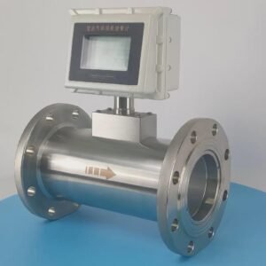
Тепловые массовые расходомеры (also called thermal dispersion meters) measure the thermal energy absorbed by the flowing gas — a value that is directly proportional to mass flow. A heated sensor loses heat to the flowing gas at a rate dependent on mass velocity. No pressure or temperature compensation is needed for the base mass flow reading, which is why thermal meters are the default choice for industrial gas measurement in applications where Coriolis would be cost-prohibitive.
Typical thermal mass meter accuracy is ±1–2% of full scale for standard models и ±0.5–1% of reading for laboratory-grade instruments — lower than Coriolis, but sufficient for compressed air, nitrogen purge, natural gas process feed, and combustion air monitoring applications. As documented by Fox Thermal’s technology comparison, thermal meters outperform differential pressure meters in gas applications on accuracy, turndown (10:1 to 100:1), and total installed cost.
Thermal meters are not suitable for liquid measurement and require calibration with the actual gas composition — a nitrogen-calibrated meter measuring a 70% methane/30% CO₂ blend will read incorrectly without a multi-gas calibration adjustment.
Differential Pressure: Lower Cost, Lower Accuracy
Differential pressure (DP) flow meters — including orifice plates, V-cone meters, and averaging pitot tubes — infer flow rate from the pressure drop across a restriction. The flow-squared relationship between pressure drop and flow rate limits turndown to 3:1 to 5:1, and permanent pressure loss consumes pump energy continuously. Accuracy of ±1–2% of reading is standard under ideal conditions, degrading to ±3–5% in installations with poor upstream conditioning or worn restriction elements.
DP meters remain appropriate for high-temperature steam applications (where no other technology handles the conditions cost-effectively), large-pipe-diameter gas measurement where Coriolis is impractical, and budget-constrained monitoring applications where ±2% accuracy is acceptable.
| Технологии измерительных приборов | Mass Flow Accuracy | Подготовка номера ко сну | Перепад давления | Best Application | Relative Cost |
|---|---|---|---|---|---|
| Кориолис | ±0.05–0.1% (liquid) | Up to 100:1 | Moderate–High | Custody transfer, dosing, batching | |
| Thermal Mass | ±0.5–2% of FS | 10:1–100:1 | Very Low | Industrial gas, compressed air | $$ |
| Электромагнитный | ±0.2–0.5% (volumetric) | 10:1–30:1 | Нет | Conductive liquid process monitoring | $$ |
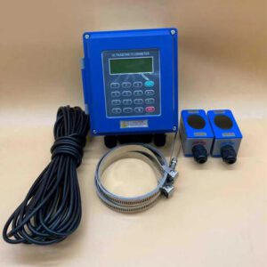
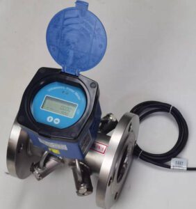
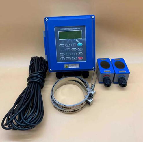
| Ultrasonic (Transit-Time) | ±0.5–1.0% (volumetric) | 10:1–50:1 | Нет | Clean liquid, large pipes, retrofit | $ |
| Турбина | ±0.25–0.5% (volumetric) | 10:1 | Низкий | Clean liquid, gas, custody transfer | $$ |
| Differential Pressure | ±1.0–2.0% (inferred) | 3:1–5:1 | High (permanent) | Steam, high-temp gas, large pipe | $ |
Source: Manufacturer specification data, Jade Ant Instruments Coriolis flow meter guide, Fox Thermal technology comparison.

Thermal mass flow meters are the preferred choice for industrial gas applications — direct mass reading without pressure or temperature compensation, and a turndown ratio that handles the wide flow range typical of compressed air and process gas systems.
Solution 3: Optimize Installation Design and Piping Configuration
You can specify the most accurate meter on the market and consistently underperform its calibrated accuracy by 3–5% through poor installation. This is not hypothetical — it is the most common cause of commissioning-stage accuracy failures in OEM skid systems.
Upstream and Downstream Straight Pipe
Flow profile disturbances — the asymmetric velocity patterns created when fluid passes through an elbow, valve, reducer, or tee — persist for significant distances downstream of the disturbance. A turbine meter or electromagnetic meter installed in that disturbed flow region sees a distorted velocity profile and produces a systematically biased reading.
The standard minimum requirements:
- Turbine meters: 15D upstream, 5D downstream (where D = pipe inner diameter)
- Electromagnetic meters: 5D upstream, 2–3D downstream
- Vortex meters: 15–20D upstream, 5D downstream
- Coriolis meters: No straight-run requirement — immune to flow profile disturbances
- Thermal mass (insertion): 20–30D upstream, 10D downstream (most sensitive technology)
For skid-mount OEM applications where the full straight-run is not achievable, two solutions maintain accuracy without changing the pipe layout: flow conditioners (perforated plates or tube bundle straighteners installed 5D upstream of the meter) reduce effective straight-run requirements to 5–10D; dual-path or multi-path meter designs with self-averaging measurement architectures reduce sensitivity to profile disturbances versus single-path designs.
The critical action point: specify straight-run requirements on the P&ID at the design stage, not after the skid frame is fabricated and the pipe layout is fixed. Retrofitting a flow conditioner into a completed skid is possible but expensive — preventing the problem costs one paragraph in the instrument specification.
Vibration Isolation
Vibration is the silent killer of Coriolis meter accuracy in OEM and industrial applications. Coriolis meters operate by measuring a shift in tube vibration frequency caused by the flowing mass. External vibration at or near the tube’s natural resonant frequency (typically 80–1,000 Hz depending on tube design and size) introduces noise that the transmitter cannot distinguish from the measurement signal, producing erratic readings or complete measurement failure.
The installation rules for vibration-sensitive meters:
- Mount on rigid, independently supported pipe — not cantilevered from the meter body
- Maintain physical distance from pumps, compressors, and centrifuges (minimum 1m of pipe with at least one flexible connection or vibration isolator between the vibration source and the meter)
- Do not mount vibrating equipment on the same structural frame as a Coriolis meter
- For high-vibration environments, specify a Coriolis model with enhanced vibration rejection (modern dual-frequency drive transmitters distinguish process signal from environmental noise through frequency discrimination)
Turbine meters are also affected by vibration — external vibration can cause the rotor to spin erratically at zero flow, producing false readings and accelerating bearing wear. Vibration isolation through flexible pipe connectors and isolated mounting brackets applies to turbine meter installations in pump and compressor environments as well.
Meter Orientation
Many meter technologies have preferred installation orientations that affect accuracy and long-term reliability. The руководство по установке расходомеров from Jade Ant Instruments covers orientation requirements across all major meter families. The most common orientation-related errors:
Horizontal installation of a Coriolis U-tube meter where the tube bends face downward creates a drainage problem — trapped fluid accumulates in the tube bends during shutdown, exposing the tubes to corrosion and creating a phase separation condition at startup. Specify straight-tube Coriolis designs for applications that require full drainability.
Vertical downward-flow installation of a thermal mass meter allows condensate to accumulate on the heated sensor element — altering the heat transfer characteristics and producing systematic low readings. Thermal meters should be installed in vertical upward-flow or horizontal configurations.
Installation of a magnetic flow meter in a section of pipe that is not consistently full will produce erratic or zero readings. Mag meters must be installed with the pipe full — which means installing in vertical upward-flow on applications that can drain, or in horizontal pipe runs with the meter at the lowest point in the system.
Solution 4: Leverage Smart Diagnostics and Real-Time Monitoring
The most accurate meter you have installed today is underperforming somewhere in your fleet right now. The challenge is not whether drift, coating, or wear is occurring — it is whether you know about it before it causes a problem.
Smart diagnostics — embedded firmware that continuously monitors meter health parameters and alerts when something changes — shift the maintenance model from reactive (respond when something fails or a discrepancy is reported) to predictive (schedule an intervention when the data indicates a developing condition).
What modern smart transmitters monitor in real time:
Для Кориолисовые расходомеры: tube vibration amplitude and drive gain (increasing drive gain indicates tube coating or partial blockage), zero stability (drift in the zero-flow reading indicates mounting stress changes or tube condition changes), fluid density (sudden density changes flag phase changes or fluid composition shifts), and signal noise metrics that distinguish external vibration from process measurement.
Для electromagnetic meters: electrode coating or fouling (detected through changes in electrode impedance), empty-pipe detection (critical for preventing false readings when pipe drains), power supply quality, and process ground continuity (ground faults produce EMF noise that corrupts the measurement).
Для turbine meters: pulse signal quality (irregular pulse spacing indicates bearing wear or rotor damage), low pulse amplitude (signals pickup sensor degradation or rotor fouling), and zero-flow drift (false pulse counts at zero flow indicate electrical interference or bearing debris).
IIoT integration pathways. A smart transmitter’s diagnostic data is only valuable if someone receives and acts on it. The integration pathway from field meter to maintenance team depends on the plant’s communication infrastructure:
HART 7 protocol carries up to 35 configurable process and diagnostic variables over the existing 4–20mA wiring. A HART multiplexer or asset management server (such as Emerson’s AMS Device Manager or Honeywell’s Field Device Manager) polls all HART-enabled meters on a scheduled basis and logs diagnostic values to a central database — where trending analysis identifies gradual degradation before it reaches an alarm threshold.
Modbus TCP or MQTT over Ethernet carries the same diagnostic data to SCADA systems and cloud platforms in real time, without the polling latency of HART. For EPC projects specifying new facilities with Ethernet-based field device networks (Ethernet APL), all meter diagnostics are available at the control room continuously.
A real-world payoff: A pipeline operator who deployed HART-enabled Coriolis transmitters across 18 measurement stations analyzed diagnostic trending data over 24 months. The data identified tube coating progression on 4 meters (increasing drive gain trend) and zero drift on 3 meters (mounting stress from thermal expansion). All 7 meters were cleaned or re-mounted during planned shutdowns. None required emergency response. The avoided emergency callout cost — estimated at USD 8,000–15,000 per event — represented a diagnostic ROI that paid for the HART multiplexer system within the first year.
Solution 5: Apply Advanced Compensation Algorithms for Temperature, Pressure, and Fluid Properties
Every flow meter is calibrated at specific reference conditions — typically a reference fluid (often water for liquid meters, dry air or nitrogen for gas meters), at a defined temperature and pressure. When the actual operating conditions differ from the calibration conditions, the reading carries systematic error unless the meter (or its associated flow computer) applies a correction.
Temperature compensation is the most universally applicable correction. Temperature affects fluid density and viscosity, both of which influence flow measurement. For a Coriolis meter measuring a petroleum product at 60°C rather than the calibration reference of 15°C, the fluid density has decreased by approximately 3–5% depending on the specific gravity of the product. Without temperature correction, the volumetric flow inferred from mass flow and density will be in error by the same proportion.
Modern Coriolis transmitters apply temperature compensation continuously using an integrated RTD (Resistance Temperature Detector) sensor that measures actual fluid temperature and adjusts the density calculation in real time. As documented in the 2024 Kutin et al. paper inMeasurement, temperature compensation algorithms in commercial Coriolis meters correct for thermal expansion and contraction of the vibrating tube itself, ensuring the measurement remains accurate across operating temperature ranges without manual recalibration.
Pressure compensation matters primarily for gas applications. Gas density is proportional to absolute pressure — a gas flowing at 10 bar absolute has 10 times the density (and mass per unit volume) of the same gas at 1 bar absolute. A gas turbine meter or thermal mass meter calibrated at atmospheric conditions will systematically underread by a factor proportional to the operating/calibration pressure ratio, unless PTZ (Pressure-Temperature-Compressibility) compensation is applied. The flow computer takes live pressure transmitter input, calculates the compressibility factor Z using the AGA-8 or GERG-2008 equation of state, and corrects the volumetric flow reading to standard conditions (typically 0°C, 1.01325 bar).
Viscosity correction extends the accurate operating range of turbine and rotary positive displacement meters into fluid services where viscosity varies significantly with temperature. The manufacturer provides a K-factor correction curve showing the meter’s actual K-factor (pulses per unit volume) as a function of Reynolds number, which is derived from actual fluid viscosity and flow velocity. A flow computer configured with this correction curve continuously adjusts the K-factor applied to the pulse count, maintaining accuracy across the full operating viscosity range.
Dynamic density compensation for Coriolis handles applications where fluid composition changes over time — a common scenario in batch processing, multi-product pipelines, and blending systems. Because the Coriolis meter simultaneously measures density, the transmitter can track real-time density changes and apply the appropriate mass flow correction without requiring any operator intervention or reconfiguration.
Firmware upgradeability is the practical future-proofing element of compensation algorithms. When a regulatory standard updates its gas compressibility calculation method (as the transition from AGA-8 1992 to GERG-2008 required), instruments with field-upgradeable firmware can be updated without hardware replacement. For OEM manufacturers whose equipment may be in service for 15–20 years, specifying instruments with a published firmware update policy — and a supplier who maintains it — is the difference between a product line that stays compliant and one that requires a costly instrumentation replacement project.

Coriolis Mass Flow Meter — Principle of Operation (Brooks Instrument): A clear, concise explanation of how Coriolis measurement works — including the phase shift principle, density measurement, and transmitter architecture. Useful for technical briefings with customers or commissioning teams.
Case Study Snapshot: How an OEM Skid Manufacturer Reduced Measurement Error by 68%
A manufacturer of chemical dosing and blending skids serving pharmaceutical and specialty chemical customers was experiencing a pattern that had become a significant business problem: approximately one in four skids shipped generated a customer complaint within 18 months related to dosing inaccuracy. The complaint profile was consistent — product batches were drifting out of spec, and the customer’s QC data pointed to flow measurement as the contributing factor.
The investigation revealed three concurrent problems.
First, the OEM was using standard turbine meters — specified because of their familiar price point and short lead time — on chemical lines where the process fluid viscosity ranged from 3 cSt at operating temperature to 45 cSt at startup temperature. The turbine meters had not been configured with viscosity correction curves, meaning that during startup (high viscosity, low Reynolds number), the meters were reading consistently 8–12% low. Batches initiated during warmup were systematically under-dosed.
Second, the skid piping design placed the turbine meters 80mm downstream of a 90° elbow — approximately 1.6D upstream straight run, against the recommended 15D. The resulting flow profile disturbance produced a consistent 3–5% over-read at normal operating flow rates.
Third, the turbine meters had not been recalibrated since factory acceptance — some units had been in storage for up to 14 months before shipment, and no pre-installation verification had been performed.
The intervention combined three of the five solutions:
The OEM replaced turbine meters on chemical service lines with Кориолисовые расходомеры — eliminating both the viscosity-dependency and the flow-profile-disturbance sensitivity in a single change. For water-based lines where Coriolis cost was difficult to justify, they added flow conditioners upstream of the turbine meters to reduce effective straight-run sensitivity. They implemented a pre-shipment verification protocol requiring each flow meter to be tested at actual operating conditions before the skid left the factory.
Results at 18-month post-change review:
- Batch dosing measurement error (compared to gravimetric reference): reduced from average 7.2% to average 2.3% — a 68% reduction in measurement error
- Customer complaints attributable to flow measurement: dropped from 26% of shipped skids to 6%
- Factory calibration time per skid: increased by 4 hours (verification step)
- Avoided warranty and service calls per year: estimated USD 140,000 based on previous service visit cost data
The incremental meter cost (Coriolis versus turbine on chemical lines) was approximately USD 2,800 per measurement point. At an average of 3.2 chemical service measurement points per skid and an estimated avoided service cost of USD 4,200 per avoided callback, the payback per measurement point was under 8 months.
Partnering for Precision: How Distributors and MRO Teams Support Long-Term Accuracy
Flow measurement accuracy is not a set-and-forget achievement. It degrades over time unless the right support infrastructure is in place to maintain it.
For instrument distributors, the accuracy lifecycle is where long-term customer relationships are built or lost. A distributor who sells a Coriolis meter and provides no follow-up calibration support has delivered a transaction. A distributor who sells the meter, provides the first calibration at 12 months, recommends a firmware update when the manufacturer releases one, and calls the customer at month 18 to schedule the next verification has built a service relationship that competes on value rather than price.
The practical support services that maintain accuracy over time:
Calibration services — either in-house ISO 17025-accredited flow calibration benches or partnerships with accredited third-party laboratories — allow distributors to offer traceable calibration certificates without requiring customers to ship meters to the factory. For customers managing dozens of measurement points, a regional calibration resource with quick turnaround is a meaningful service differentiator.
Genuine spare parts availability — particularly for wearing components like turbine bearings, thermal sensor elements, and Coriolis tube replacement kits — means that when a meter needs service, the customer is not waiting six weeks for an import shipment. For MRO teams managing maintenance schedules for continuous operations, parts availability is often a higher priority than the meter’s original price.
Technical training — application seminars, commissioning workshops, and troubleshooting webinars — gives distributor sales and service teams the competence to advise customers on calibration intervals, installation requirements, and diagnostic interpretation. A technically competent distributor team reduces the OEM manufacturer’s field support burden while increasing the distributor’s customer retention rate.
Firmware update management — tracking the firmware versions deployed across a customer’s installed meter base and proactively notifying when critical updates or accuracy improvements are available — is a service that smart instrument manufacturers increasingly make available through partner portals.
Инструменты "Нефритовый муравей supports its distributor and MRO partners with complete technical documentation packages, calibration certificate templates, application engineering consultations, and direct technical support channels for non-standard applications. For distributors building a flow measurement service capability, the Jade Ant contact page is the starting point for discussing partnership program terms.

Real-time diagnostic monitoring across multiple measurement points gives operations teams the ability to see accuracy degradation before it becomes a compliance problem — shifting the maintenance model from reactive to predictive.
Next Steps: Audit Your Current Flow Measurement Performance
The gap between your flow meters’ specification sheet accuracy and their actual in-service accuracy is almost always larger than you expect — and almost always fixable.
Before specifying new equipment or planning a measurement improvement project, use this checklist to assess where your current system stands:
Calibration Status
- Is every flow meter in your fleet on a documented calibration schedule with a defined interval?
- Are calibration certificates traceable to NIST or an equivalent national metrology institute?
- Has any meter exceeded its calibration interval without a verified extension justification?
- Do calibration conditions (fluid, temperature, pressure) match actual operating conditions?
Installation Condition
- Are straight-pipe run requirements met for all turbine, vortex, and thermal mass meter installations?
- Are Coriolis meters installed with proper vibration isolation from pumps, compressors, and VFDs?
- Are all meters installed in their manufacturer-recommended orientation?
- Are meter bodies properly supported — not cantilevered from the pipe?
Technology Match
- Is the specified meter technology capable of the accuracy level the application requires?
- Are meters with viscosity-sensitive response (turbine, PD) configured with viscosity correction curves?
- Are gas meters configured with pressure and temperature compensation inputs for PTZ correction?
Integration and Signal Verification
- Has every meter’s output scaling been verified against a known flow reference at commissioning?
- Are pulse output counters configured for the actual meter K-factor and maximum expected frequency?
- Have SCADA/PLC tag scaling factors been cross-checked against meter calibration data?
Diagnostic Monitoring
- Are smart meters’ diagnostic outputs being monitored and trended — not just alarmed on limit exceedance?
- Is there a process for responding to diagnostic alerts before they escalate to measurement failures?
If more than three items on this checklist are unchecked, your flow measurement accuracy is meaningfully lower than your specifications indicate — and the gap is costing you in product loss, energy waste, or compliance exposure.
For a structured assessment of your specific measurement points, the electromagnetic flow meter accuracy guide for EPC systems from Jade Ant Instruments provides a technology-specific evaluation framework, including installation condition scoring and recommended corrective actions by meter type.
Glossary of Key Technical Terms
Mass Flow: The quantity of matter passing through a pipe per unit time, expressed in kg/h or lb/min. Independent of temperature and pressure — the same mass of fluid has the same mass flow reading regardless of whether it is measured at 20°C or 80°C. Critical for custody transfer, dosing, and batching where actual quantity of material matters.
Volumetric Flow: The volume of fluid passing through a pipe per unit time, expressed in L/min or m³/h. Varies with temperature and pressure because fluids expand when heated and compress under pressure. Must be corrected to standard conditions for custody transfer comparison.
Coriolis Effect: The inertial force experienced by a moving mass in a rotating reference frame — in a Coriolis flow meter, the vibrating tube acts as the rotating reference frame. The flowing fluid generates a measurable phase shift in the tube vibration proportional to mass flow rate.
K-factor: The calibration constant of a turbine flow meter — expressed in pulses per unit volume (e.g., pulses per liter). Changes with bearing wear and fluid viscosity. Must be matched to actual operating conditions for accurate totalizing.
Sensor Drift: The gradual change in a meter’s output signal over time without a corresponding change in the actual process variable. Can result from bearing wear (mechanical), electrode coating (electromagnetic), or sensor element aging (thermal mass). Detected and corrected through periodic calibration.
PTZ Compensation: Pressure-Temperature-Compressibility correction for gas flow measurement. Converts actual volumetric flow (measured at operating pressure and temperature) to standard volumetric flow at reference conditions (typically 0°C, 1.01325 bar) using the real gas equation of state.
NIST Traceability: An unbroken documentation chain linking a meter’s calibration to the primary flow standards maintained by the US National Institute of Standards and Technology (NIST), or an equivalent national metrology institute. Required for legally defensible custody transfer measurement.
Drive Gain (Coriolis): The amount of energy the transmitter must supply to maintain the tube vibration at its set amplitude. Rising drive gain indicates increasing mass in or on the tube — typically from coating buildup or partial blockage. A key predictive maintenance indicator.
Reynolds Number: A dimensionless ratio of inertial to viscous forces in a flowing fluid. Determines whether flow is laminar or turbulent and governs the K-factor behavior of turbine meters in variable-viscosity service. Low Reynolds number = viscous regime, non-linear turbine response.
In-Situ Verification: A method for checking a Coriolis meter’s accuracy without removing it from the process. The transmitter runs an internal diagnostic sequence that checks tube integrity, zero stability, and drive circuit performance, and generates a verification report without interrupting the process.
Часто задаваемые вопросы (FAQ)
1. Why is mass flow accuracy more important than volumetric flow in industrial applications?
Volumetric flow tells you how much space the fluid is occupying at a specific temperature and pressure. Mass flow tells you how much material is actually there — regardless of temperature or pressure conditions. For billing, dosing, custody transfer, and process control, the quantity of material is what matters. A volumetric reading of 100 L/min at 80°C and at 20°C represent different amounts of liquid — the hot fluid has expanded. A mass flow reading is consistent across both temperatures because mass doesn’t change with temperature. In custody transfer, tax and invoicing are based on mass or standard volume. In pharmaceutical dosing, recipe compliance is based on mass of active ingredient. In combustion control, fuel efficiency is calculated from fuel mass, not volume. Wherever the material quantity — not the space it occupies — drives the decision, mass flow is the measurement that eliminates ambiguity.
2. How often should flow meters be calibrated in industrial OEM systems?
The interval depends on three factors: the application’s accuracy requirement, the operating environment’s aggressiveness, and the technology’s known drift rate. Custody transfer and fiscal billing applications require calibration every 6–12 months — some contracts specify semi-annual. Pharmaceutical dosing under GMP requires annual calibration as a minimum, with in-situ verification between events. General process monitoring where ±2% is acceptable can use 24–36 month intervals with condition-based extensions supported by diagnostic trending data. The worst approach is a fixed universal interval applied without considering actual drift data. A better approach: use the first two calibration cycles to measure actual drift rate, then set the interval at the point where drift would reach the application’s uncertainty limit — not before. This risk-based calibration management approach is detailed in the ISO 17025 calibration standard and is increasingly required by major industrial clients in their supplier quality programs.
3. What are the warning signs that a flow meter is losing accuracy?
The earliest warning sign is a trend, not a reading. A meter that reads 2% low on Monday and 2% low on Friday has a stable error that calibration can correct. A meter that reads 2% low on Monday and 3% low on Friday is drifting — and the drift will continue unless the cause is identified and addressed. Specific warning patterns: increasing discrepancy between this meter and a downstream meter on the same line; unexplained product yield variance that correlates with shift or operating temperature; the meter’s last “as-found” calibration deviation was larger than the previous event; drive gain trending upward in a Coriolis meter; irregular pulse output from a turbine meter that previously showed clean signals; reduced signal amplitude on an electromagnetic meter’s diagnostic output. Any of these patterns, if monitored and trended, provides weeks to months of advance warning before the meter’s accuracy falls below its specification limit.
4. Can environmental factors like vibration or temperature affect mass flow accuracy?
Yes — and the mechanism differs by technology. Coriolis meters vibrate their tubes at a precisely controlled frequency. External mechanical vibration at or near that frequency (80–1,000 Hz depending on the design) superimposes noise on the measurement signal that the transmitter may misinterpret as flow signal. The result ranges from noisy readings to completely erroneous output. The fix is mechanical vibration isolation — physical separation from vibration sources, flexible pipe connections, and rigid independent mounting. Temperature affects meter accuracy primarily through its effect on fluid properties (density, viscosity) and material dimensions. A Coriolis meter’s tube stiffness changes with temperature — modern transmitters compensate continuously using the integrated RTD, but an extremely rapid temperature change (thermal shock from steam-cleaning a pharmaceutical process line) can cause transient inaccuracy that persists until thermal equilibrium is restored. Electromagnetic meters experience thermal effects at their electrode connections and liner material. Proper material selection for the operating temperature range, as described in the flow meter material selection guide, prevents the majority of temperature-related accuracy problems.
5. Which flow meter technology offers the highest accuracy for mass flow measurement?
Coriolis flow meters, definitively. With liquid mass flow accuracy of ±0.05% to ±0.1% of reading under reference conditions — and stated uncertainties as low as ±0.05% for premium calibration-grade models — Coriolis meters are used as reference standards for verifying other flow meters. No other commercial flow meter technology comes close to this accuracy for direct mass measurement. For gas measurement, Coriolis achieves ±0.25–0.5% of reading — still better than thermal mass (±0.5–2% of FS) and significantly better than differential pressure (±1–2%). The accuracy advantage compounds over time because Coriolis meters exhibit minimal drift — the tube geometry that determines the measurement is mechanically stable, and the measurement principle is immune to fluid property variations that cause other technologies to drift. The practical implication: for any application where a measurement error has a direct financial consequence above USD 5,000/year, a Coriolis meter’s accuracy premium versus a turbine or DP meter pays for itself in reduced product giveaway and avoided custody transfer disputes within the first 12–18 months.
6. How do I ensure proper installation of a mass flow meter on a skid system?
Start with the manufacturer’s installation data sheet — not the abbreviated quick-start guide, but the full installation and operations manual that specifies orientation, straight-run requirements, grounding, vibration isolation, and process connection torque specifications. Apply these requirements at the P&ID design stage, before the skid frame is built. Verify during fabrication that the actual pipe layout matches the specification. Conduct a pre-commissioning walkdown using a meter installation checklist that covers: confirmed upstream/downstream pipe run lengths, verified meter orientation, vibration isolation confirmed (flexible connections or physical separation from vibration sources), grounding confirmed (for electromagnetic meters — a missing ground ring on an HDPE pipe causes measurement failure), and zero-flow verification completed with the pipe filled and isolated. Post-commissioning, verify the meter’s output against a reference measurement at two or three flow rates before logging the readings as operational data. This structured approach — specification, fabrication verification, commissioning checklist, and output verification — eliminates the majority of installation-related accuracy problems before any product flows.
7. Can smart flow meters reduce maintenance costs for MRO teams?
Yes — with documented results. The maintenance cost reduction comes from two mechanisms: earlier detection of developing problems (allowing planned rather than emergency interventions) and elimination of unnecessary scheduled maintenance on meters that diagnostic data confirms are operating within specification. An MRO team managing 150 measurement points on a calendar-based annual inspection schedule conducts 150 meter inspections per year regardless of which meters actually need attention. A team with smart meters using HART diagnostic trending identifies which 20–30 meters are showing degradation indicators and schedules those for inspection while deferring the remaining 120 meters to a longer verification interval. The reduction in total maintenance events is typically 30–50% in installations with good diagnostic monitoring practices. The avoided emergency callout value — typically 3–5× the cost of a planned maintenance event — adds a further economic benefit when developing faults are caught before they cause measurement failures.
8. What role do instrument distributors play in maintaining flow accuracy?
Distributors are the closest technical support resource for the majority of end users in industrial and municipal applications — closer than the manufacturer and more accessible than a major engineering consultancy. Their role in accuracy maintenance covers five practical areas: providing NIST-traceable calibration services or connecting customers with accredited calibration laboratories; stocking genuine spare parts (bearings, electrode assemblies, sensor elements) for rapid replacement when worn components are identified; delivering firmware updates and notifying customers when accuracy-related firmware improvements are released; providing technical training that helps customer maintenance teams interpret diagnostic outputs and conduct basic commissioning verification; and flagging installation problems during site visits that the customer’s internal team may not have the specialized knowledge to identify. For customers managing large meter populations, a distributor who offers a managed calibration program — tracking each meter’s calibration due date and scheduling service proactively — removes the administrative burden of calibration management from the customer’s maintenance team entirely.
9. How does fluid composition affect mass flow measurement?
Fluid composition changes affect different meter technologies differently. For Coriolis meters, a change in fluid density changes the tube vibration frequency — and the meter reports the actual density in real time. Mass flow measurement is unaffected by density changes because it is a direct inertial measurement, not density-dependent. For volumetric meters (turbine, electromagnetic, ultrasonic), a density change produces a mass flow error equal to the density change percentage if the meter’s density compensation is not updated. For thermal mass meters measuring gas, a composition change affects the gas’s heat capacity — the fundamental property the meter uses to infer mass flow. A thermal meter calibrated for methane will systematically over- or under-read when the gas composition shifts toward CO₂ or nitrogen. Multi-gas thermal meters address this through user-configurable composition correction tables or built-in gas libraries, but the correction requires the user to know the composition and input it correctly. For applications with variable or unknown gas composition, a Coriolis meter’s composition independence makes it a significantly more reliable choice despite the higher cost.
10. Are there industry standards for flow measurement accuracy in custody transfer?
Yes — and they are enforceable requirements, not guidelines, in most custody transfer contracts. The key standards by application:
API MPMS (Manual of Petroleum Measurement Standards): Governs petroleum liquid and natural gas custody transfer in North America. Chapter 5.3 covers turbine meters for liquid service (±0.25% accuracy requirement). Chapter 5.6 covers Coriolis meters for liquid service. Chapter 22 covers ultrasonic meters for liquid service.
ISO 10790: International standard for Coriolis meter measurement uncertainty, calibration, and application requirements — referenced in European and international custody transfer contracts.
OIML R117: International legal metrology recommendation for measuring systems for liquids other than water — defines accuracy classes (0.3%, 0.5%, 1.0%) for fiscal measurement of petroleum products and chemicals. Implemented through national legal metrology legislation in most countries.
ISO 4064 / OIML R49: Standards for water meters used in municipal billing — defines accuracy class requirements and calibration traceability for potable water custody measurement.
Compliance with these standards is not achieved at meter purchase — it requires ongoing calibration at specified intervals, documented calibration records, and in-service verification using approved proving methods. For OEM equipment sold into custody transfer applications, the compliance obligation follows the meter for its entire service life.
11. Can flow meter accuracy impact energy efficiency in utility systems?
Directly and significantly. A flow meter that reads 3% low on a steam supply line causes the boiler control system to add 3% more fuel than the process requires — because the control loop is trying to maintain a setpoint that the meter is underreporting. On a 10 MW steam system, a 3% fuel excess represents approximately USD 150,000 per year in wasted fuel at typical industrial gas prices. On a chilled water system, inaccurate flow data prevents the building management system from optimizing chiller staging — potentially running two chillers at 40% load each instead of one at 80%, consuming 15–25% more electricity for the same cooling output. Municipal water utilities with inaccurate district flow meters cannot identify which pressure zones are consuming disproportionate energy in pumping — the metering data they need to optimize pump scheduling doesn’t reflect reality. Every percentage point of flow measurement error that affects a control or optimization system translates to a proportional energy efficiency penalty.
12. What should EPCs consider when specifying flow meters for integrated systems?
EPC instrument engineers face a specification decision that affects every stakeholder downstream: the client who will operate the system, the commissioning team that will set it up, and the MRO team that will maintain it. The specification framework should cover eight elements: (1) accuracy requirement — what level of measurement uncertainty does the application actually need? (2) fluid properties — conductivity, viscosity, temperature, pressure, solids content, and whether composition is stable or variable; (3) flow range and turndown — minimum and maximum expected flow rates at all operating modes including startup; (4) installation constraints — available straight run, orientation, space for the meter body, and vibration environment; (5) communication protocol — must match the plant’s PLC/DCS platform without custom integration hardware; (6) certifications required — ATEX zone, SIL level, API/OIML standard, NSF contact approval; (7) calibration serviceability — is an accredited calibration facility accessible within the project’s operational region?; (8) long-term supplier support — will firmware updates, spare parts, and technical support be available for the expected 15–20 year service life? Skipping any of these elements creates a specification gap that becomes a project problem — typically at the commissioning stage when it is most expensive to correct.
13. How can OEMs future-proof their equipment for evolving accuracy demands?
The practical answer is to design for upgradeability rather than for current specifications only. Three decisions at the OEM product design stage create future flexibility: specify instruments with field-upgradeable firmware accessed via a digital interface (HART, Modbus, or Ethernet) — this allows accuracy improvements, new compensation algorithms, and updated gas property libraries to be deployed without hardware replacement; use modular transmitter designs that separate the sensor element from the transmitter electronics — transmitter technology evolves faster than sensor technology, and a modular design allows the transmitter to be upgraded without changing the process connection or recalibration the sensor; and select open communication protocols (HART 7, Modbus TCP, OPC UA) rather than proprietary interfaces — ensuring that the instrument remains compatible with future control system upgrades without vendor lock-in. OEMs who built systems in 2015 with HART-equipped instruments and Modbus TCP outputs found it straightforward to connect those systems to 2025 IIoT platforms. Those who specified proprietary protocols in 2015 are facing complete instrument replacement projects to achieve the same connectivity.
14. Is it possible to verify flow meter accuracy in the field without removal?
Yes — and for Coriolis meters, this capability is now a standard feature from major manufacturers. Проверка на месте (also called smart meter verification or Electronic Verification) runs a diagnostic sequence from the transmitter without interrupting the process. The transmitter checks tube mechanical integrity, zero stability, drive circuit performance, and signal quality, generating a verification report that documents whether the meter is operating within its original calibration specification. If the in-situ verification passes, the calibration interval can often be extended without a formal wet-flow calibration — reducing calibration cost and process disruption. ABB’s automatic in-situ verification technology for their Coriolis meters demonstrates tube integrity detection through tube thinning, coating, and corrosion assessment — without process shutdown. For turbine meters, a portable clamp-on ultrasonic reference meter provides a field verification method: compare the turbine meter’s reading against the clamp-on meter at the same flow conditions. A deviation within the combined uncertainty of both instruments confirms the turbine meter is performing to specification; a deviation outside that range triggers a formal calibration.
15. What are the cost implications of poor flow measurement accuracy?
The visible cost is the gap between what the meter says and what actually flowed. The invisible cost is everything the business does in response to that gap. Product giveaway — shipping more product than invoiced because the outbound meter reads low — is typically 0.5–2% of product volume in systems with unchecked meter drift. On a production line processing USD 5 million of product per year, a consistent 1.5% giveaway error costs USD 75,000 per year in lost revenue. Regulatory compliance fines for inaccurate emissions reporting range from $5,000 to $25,000 per violation (Sage Metering). Customer disputes triggered by metering discrepancies in custody transfer — where the seller’s meter and the buyer’s meter disagree — require independent proving runs, legal review, and sometimes contract renegotiation. Energy overconsumption from inaccurate control system inputs (over-pumping, over-heating, sub-optimal compressor staging) typically adds 3–8% to energy costs on systems where flow measurement is the primary control input. Taken together, the annual cost of poor flow measurement accuracy in a mid-sized process facility is almost always larger than the capital cost of replacing every poorly performing meter in the plant — which is the economic argument for proactive meter assessment and investment in higher-accuracy technology where it is justified.
For application-specific consultation on improving flow rate mass accuracy in your OEM equipment, skid systems, or process plant — including meter technology selection, calibration program design, and installation review — contact Инструменты "Нефритовый муравей for a free technical assessment.
Additional technical resources:
- Top Coriolis mass flow meters for industrial use — Jade Ant Instruments
- Coriolis flow meter pros, cons, and 2026 selection guide — Jade Ant Instruments
- Flow meter installation best practices guide — Jade Ant Instruments
- NIST fluid metrology and flow standards — National Institute of Standards and Technology
- Flowmeter calibration — 5 best practices — Fluke Corporation
- In-situ calibration validation methods for process meters — Processing Magazine
- Hidden costs of inaccurate gas flow measurement — Sage Metering