Introduction: Why Installation Type Is a Strategic Decision
Every flow measurement project involves two fundamentally different philosophies. Clamp-on technology mounts sensors on the outside of existing pipe — the process never stops, no pipe is cut, no fluid is touched. Inline installation integrates the sensor directly into the process line, delivering the signal right at the fluid boundary. The choice between them is not purely technical; it is an operational, financial, and risk management decision that reverberates across the entire lifecycle of your measurement system.
Consider a single concrete scenario: a chemical processing plant needs to add flow measurement to 14 points across three production lines. Line 1 runs 24/7 with zero scheduled downtime; Line 2 has an annual 96-hour maintenance window; Line 3 handles a mildly corrosive slurry at 160 °C. These three scenarios alone could rationally call for three different installation strategies — and applying one approach to all three is how facilities end up with measurement systems that either fail prematurely, cost twice the budgeted amount to maintain, or deliver data that process engineers distrust enough to ignore.
This guide is written specifically for flow instrumentation distributors, agents, and the plant managers they serve — professionals who need to evaluate technology not in the abstract but against real operational constraints: production schedules that cannot slip, CAPEX budgets that were approved six months ago, and maintenance teams that are already stretched thin. By the end, you will have a structured decision framework you can apply immediately to your facility’s specific challenges.

Figure 1: Inline flow measurement integrated into a high-pressure industrial process line — one of two fundamental installation philosophies covered in this guide.
1. Understanding Installation Types: Core Differences and Applications
Clamp-On Technology: Definition and Core Principles
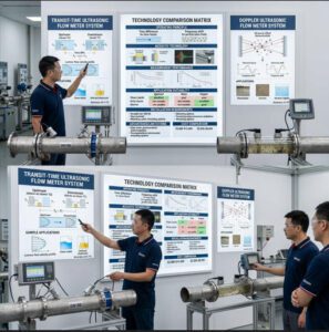
Clamp-on flow meters — almost universally ultrasonic in modern industrial deployments — use two piezoelectric transducers mounted on the outside of a pipe. The transducers alternate sending and receiving ultrasonic pulses diagonally through the pipe wall and the flowing fluid. Because the flowing liquid carries a downstream pulse fractionally faster than an upstream pulse, the meter’s processor measures this transit-time difference (Δt) and converts it into a flow velocity — then multiplies by the pipe’s cross-sectional area to derive volumetric flow.
The key phrase is non-invasive: at no point does any component of the meter touch the process fluid. This is not merely a convenience — in corrosive chemical service, high-purity pharmaceutical lines, or cryogenic applications, eliminating direct fluid contact removes entire categories of contamination risk, chemical compatibility concern, and leak potential.
Clamp-on ultrasonic meters cover pipe diameters from DN25 (1 inch) to DN6000 (236 inches) in standard configurations — a range no single inline sensor technology matches. This scalability makes them the default choice for large-diameter utility lines where inline alternatives would require custom flanged spool pieces costing $15,000–$50,000 before installation even begins.
Advantages of Clamp-On Installation
✅ Operational Advantages
- Zero process disruption: Installation and maintenance completed while the line runs at full pressure and flow — no production loss, no emergency permit, no draining.
- Portable & relocatable: A single clamp-on kit can audit 30 measurement points in one day — something no inline sensor can do.
- Retrof-it ready: Mounts on existing pipe with no pipe cutting, welding, or hot-work permits.
- Lower initial cost: Typical installation time is 30–90 minutes versus 2–5 days for inline systems.
✅ Financial Advantages
- Eliminates shutdown-related production losses (which average $22,000–$260,000 per hour in mid-to-large manufacturing facilities).
- No pipe modification costs — no welding crew, no scaffolding, no pressure testing after installation.
- One portable unit can replace 5–10 fixed monitoring points on non-critical lines.
- Couplant pads (solid-state elastomers) last 5+ years, minimizing consumable cost.
Limitations of Clamp-On Installation
The non-invasive advantage comes with a physics compromise: the ultrasonic signal must travel through the pipe wall before it enters the fluid. Every millimeter of wall material, every layer of scale, every air gap in the couplant, and every degree of pipe surface irregularity introduces acoustic uncertainty. On a clean, straight run of carbon steel pipe carrying treated water, a properly installed clamp-on meter delivers ±1.0% accuracy — adequate for the vast majority of process monitoring applications. On a heavily corroded cast iron line with 6 mm of internal scale, the same meter may drift to ±5–10% or lose signal entirely.
Accuracy also degrades below DN25 (where the acoustic path becomes too short for reliable signal resolution) and in two-phase flows where entrained air or gas bubbles scatter the ultrasonic beam. Applications requiring better than ±0.5% accuracy — fiscal metering, custody transfer, batch dosing at tight tolerances — generally require inline technology.
Inline Installation: Definition and Core Principles
Inline flow meters are integrated directly into the process piping as a spool piece — a dedicated pipe section containing the sensing element, flanged at both ends to connect into the line. The sensor is in direct contact (or near-direct contact, in the case of ultrasonic wetted-transducer designs) with the flowing fluid. Common inline technologies include electromagnetic (mag) meters, vortex meters, turbine meters, Coriolis meters, and inline ultrasonic meters with wetted transducers.
Direct fluid contact eliminates the acoustic path uncertainties that constrain clamp-on performance. The meter’s geometry is precisely machined and factory-calibrated on a traceable flow rig — the acoustic or mechanical path is fixed and known, not inferred from external pipe measurements. This is why inline multi-path ultrasonic and Coriolis meters dominate custody-transfer and fiscal metering applications governed by API MPMS Chapter 5.8 and similar standards.
Advantages of Inline Installation
Inline meters deliver superior measurement accuracy — typically ±0.2% to ±0.5% for electromagnetic and single-path ultrasonic designs, and ±0.1% to ±0.2% for multi-path ultrasonic and Coriolis in ideal conditions. This accuracy is stable over time because the sensing geometry is physically fixed; there is no couplant to degrade and no pipe wall variation to account for. They also handle wider operating envelopes: electromagnetic meters operate reliably at temperatures from −40 °C to +180 °C and pressures exceeding 40 bar, while Coriolis meters tolerate even more extreme conditions.
For process control applications where measurement data feeds into automated control loops — chemical dosing, proportional blending, custody-grade allocation metering — inline sensors provide the response time (as fast as 50 ms) and long-term calibration stability that clamp-on technology cannot match.
Limitations of Inline Installation
The primary limitation is installation-enforced downtime. To install an inline sensor, the pipe must be drained, depressurized, cut, and the spool piece flanged in. In a continuous-process chemical plant, the cost of that shutdown may easily exceed the cost of the meter itself. A mid-sized manufacturing facility paying $35,000 per hour in lost production that requires an 8-hour shutdown incurs $280,000 in opportunity cost — before a single dollar of installation labor is invoiced. Inline sensors also commit to a fixed pipe location permanently; if process requirements change, relocation means another round of pipe work.

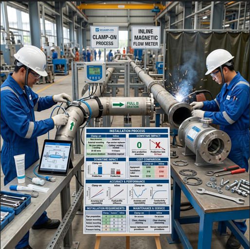
Figure 2: Clamp-on transducers mounted externally — no pipe cutting, no process shutdown, no fluid contact. Ideal for retrofit and continuous-operation environments.
2. Operational Downtime Tolerance: Making the Critical Assessment
Evaluating Your Production Schedule and Downtime Costs
Before any comparison of sensor specifications, the single most important question is: Can your facility absorb the downtime required to install an inline meter? The answer is not binary — it depends on when, for how long, and at what cost that downtime occurs.
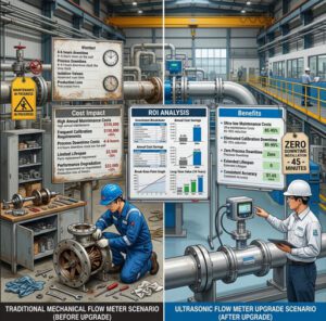
Industry data from AlphaCIS and MachineMetrics consistently shows that unplanned manufacturing downtime costs between $22,000 and $260,000 per hour depending on facility size and production value. Even planned downtime carries cost: overtime labor, expedited logistics for parts, production makeup schedules, and customer delivery penalties. When these costs are fully loaded into a TCO model, many facilities discover that a clamp-on meter costing $4,000 delivers a lower 5-year total cost than an inline sensor at $1,800 — because the clamp-on installation cost is zero in downtime terms.
24/7 Operations and Zero-Tolerance Environments
Continuous-process operations — petrochemical plants, power generation facilities, pharmaceutical production lines under GMP constraints — have processes that cannot tolerate unplanned interruption. In these environments, clamp-on technology is not a second-best alternative; it is the only viable installation method unless a bypass loop with isolation valves was deliberately engineered into the piping system.
Distributors and agents serving these markets should note that inline meters can still be specified for 24/7 operations — but only if bypass spools or hot-tap capability are included in the system design during the engineering phase. Retrofitting a bypass after the fact typically costs more than the inline meter itself.
Planned Maintenance Windows and Flexible Scheduling
Facilities with scheduled maintenance windows — annual plant turnarounds, seasonal shutdowns, weekend downtime windows in discrete manufacturing — have legitimate opportunities to install inline sensors without incurring unplanned production loss. The question becomes economic: does the accuracy improvement that inline technology provides over clamp-on justify the shutdown window, labor cost, and pipe modification expense?
For fiscal metering, safety interlock measurements, and custody-transfer points, the answer is almost always yes. For process monitoring, trend tracking, and energy sub-metering, the answer is increasingly no — especially as modern clamp-on meters from suppliers like Инструменты "Нефритовый муравей now deliver ±1.0% field accuracy with digital HART and Modbus output, fully adequate for control and reporting applications.
Hidden Downtime Costs Beyond Installation
Installation downtime is the visible cost. The hidden costs accumulate over the asset’s lifetime. Inline sensors require process isolation for maintenance — cleaning, calibration verification, and sensor replacement all demand the same pipe shutdown that the original installation required. Over a 10-year lifecycle, a meter requiring three maintenance shutdowns at 4 hours each, in a plant with $50,000/hour downtime cost, incurs $600,000 in maintenance-related shutdown costs — costs that a clamp-on meter, maintainable while the line runs, never generates.
Calculating Total Cost of Ownership (TCO) Models
| Cost Category | Ультразвуковой зажим | Inline Electromagnetic | Notes |
|---|---|---|---|
| Sensor Purchase Price | $2,500 – $5,000 | $1,800 – $4,500 | Inline often lower purchase cost at DN100 |
| Installation Labor | $150 – $400 (1 technician, 1–3 hrs) | $3,500 – $8,000 (crew, hot work, pressure test) | Largest variable for inline |
| Pipe Modification / Materials | $0 | $800 – $2,500 (flanges, gaskets, welding) | — |
| Installation Downtime Cost | $0 | $22,000 – $175,000 | 8 hrs × $22K–$22K+ /hr facility cost |
| Routine Calibration (10 yr) | $1,200 – $2,500 | $2,000 – $4,500 | Inline requires more formal verification |
| Maintenance Shutdowns (10 yr) | $0 | $0 – $50,000+ | Depends on number of required shutdowns |
| Couplant / Consumables (10 yr) | $200 – $500 | $50 – $150 (gaskets only) | — |
| Sensor Replacement (1× in 10 yr) | $2,500 – $5,000 | $1,800 – $4,500 + shutdown | Inline replacement adds downtime cost |
| 10-Year TCO Range (Low–High) | $6,550 – $13,400 | $31,950 – $248,650 | Assumes one installation downtime event |
| Sources: Installation cost ranges from contractor data; downtime cost midpoint from MachineMetrics & AlphaCIS industry reports (2025). TCO excludes pressure drop energy penalty for inline designs in high-volume flow applications. | |||
When presenting TCO to plant managers, always include the downtime cost row — it is consistently the line item that shifts the conversation from “which meter is cheaper to buy?” to “which installation approach saves us the most money?” For clients with high downtime costs (>$20,000/hr), a clamp-on system almost always wins the 10-year TCO comparison regardless of unit price differences.
Risk Assessment and Contingency Planning
Contingency planning is where experienced instrumentation distributors differentiate themselves. Every inline installation carries complication risk: unexpected pipe corrosion discovered when cutting, incorrect flange face dimensions, welding distortion that affects alignment, or pressure test failures that extend the shutdown window. A prudent project budget adds 15–25% contingency for inline installations specifically to absorb these unpredictables. Clamp-on projects have effectively zero structural installation risk — if the pipe surface is unsuitable, the response is relocating the transducers, not rescheduling a shutdown.
3. Budget Constraints: Aligning Investment with Financial Reality
Initial Capital Investment Comparison
Purchase price is the easiest cost to compare and the most misleading one to optimize in isolation. An inline electromagnetic flow meter for a DN80 water line may cost $1,500 — making it appear to be the budget-friendly choice compared to a $3,500 clamp-on ultrasonic unit. But add $5,500 in installation labor, $1,200 in pipe modification materials, and $44,000 in production downtime (2 shifts at $22,000/shift), and the “cheaper” meter has generated $52,200 in total project cost before it has measured its first cubic meter.
Note: Downtime cost uses industry median of $22,000/hr for mid-size manufacturing (Source: AlphaCIS, 2025). Actual facility cost may vary significantly.
Labor and Installation Costs
Clamp-on installation labor is straightforward: one technician, basic hand tools, and the meter’s configuration display. A properly trained technician installs and commissions a fixed clamp-on meter in 45–120 minutes. Inline installation involves a piping crew (typically 2–4 workers), specialized welding equipment or flanging tools, lockout/tagout procedures, and post-installation pressure testing — a minimum full-day commitment and often a 2–3 day project when safety permitting and drain-down are factored in.
Equipment and Material Expenses
Clamp-on ancillary costs are minimal: mounting straps or rails (~$50–$150), acoustic couplant or solid-state coupling pads (~$30–$80), and signal cable. Inline installation requires flanges (typically 2 × DN-matched raised-face flanges at $80–$400 each depending on pressure class), full-face gaskets, stud bolts, and potentially short pipe spools for alignment — totaling $800–$2,500 in materials before labor begins. For stainless steel or exotic alloy piping, these materials costs multiply by 3–8×.
Ongoing Operational and Maintenance Costs
Neither clamp-on nor inline ultrasonic technology has moving parts — no bearings to replace, no impellers to wear, no piston seals to fail. This is a significant lifecycle advantage over mechanical flow meters such as turbine or positive displacement designs, which typically require bearing replacement every 2–5 years in demanding service. The key maintenance cost driver for both technologies is calibration verification and, for clamp-on systems, periodic couplant condition checks.
Preventive Maintenance Scheduling
| Maintenance Activity | Ультразвуковой зажим | Inline Electromagnetic / Ultrasonic |
|---|---|---|
| Signal quality check & couplant inspection | Every 12 months — no shutdown, 30 min | Not applicable (wetted transducers) |
| Calibration verification | Annual comparison vs. portable reference — no shutdown | Annual, may require process isolation or in-situ verification tool |
| Sensor replacement | Unclamp old, mount new — 30 min, no shutdown | Requires process isolation, pipe access — 4–8 hrs + downtime cost |
| Transducer cleaning | External wipe-down — no shutdown | Internal cleaning if scaling — process shutdown required |
| Gasket / seal inspection | Not applicable | Every 2–5 years, during planned maintenance |
| Estimated annual maintenance cost | $200 – $600 | $400 – $1,200 (excl. downtime) |
▶ Video: Ultrasonic flow meter working principle — understanding transit-time technology helps clarify why clamp-on and inline configurations deliver different accuracy performance.
4. Pipe Material and System Compatibility: Technical Feasibility Assessment
Material-Specific Considerations for Clamp-On Systems
The single most important pre-installation check for clamp-on ultrasonic meters is pipe material acoustic compatibility. Ultrasonic signals must transit the pipe wall with acceptable attenuation — the signal loses energy at every material boundary it crosses. Carbon steel, stainless steel, and seamless copper pipe transmit ultrasonic energy efficiently and present no fundamental limitation for clamp-on measurement. PVC, HDPE, and polypropylene also work well — in fact, the lower acoustic impedance mismatch between plastic pipes and couplant sometimes produces cleaner signals than metal.
Challenges arise with: cast iron (graphite microstructure scatters ultrasonic signals, often limiting achievable accuracy to ±2–5%); concrete-lined pipe (thick liner attenuates signal severely); heavily corroded pipe with internal scale exceeding 5 mm; and composite pipes with air gaps between layers. In these cases, inline installation is not a preference — it is frequently the only path to reliable measurement.
Pipe Insulation and Coating Impact
Pipe insulation is one of the most common field complications for clamp-on installation. The standard approach is to create access windows in the insulation at the transducer mounting locations — remove insulation over a 300–400 mm length, mount transducers, apply new insulation around the transducer housings. On high-temperature lines (>80 °C surface temperature), specialized high-temperature couplant or solid-state coupling pads rated to the pipe surface temperature must be used; standard petroleum jelly or sonographic gel decomposes rapidly above 60 °C.
Extreme Material and Surface Conditions
Heavily scaled or corroded pipe interiors cause a specific measurement problem beyond simple signal attenuation: the scale layer changes the effective pipe inner diameter. If the meter’s configuration was entered with the pipe’s nominal inner diameter (as cast or rolled), but 4 mm of scale has reduced the actual flow area, the meter reads low by the ratio of the actual to configured cross-sectional areas. In a DN200 pipe (nominal ID 193 mm), 4 mm of scale on all walls reduces the ID to 185 mm — a cross-sectional area reduction of 8.2%. The meter will under-read by approximately 8% regardless of how well the ultrasonic signal performs.

Figure 3: Pipe material selection is a critical pre-installation check for clamp-on ultrasonic systems. Carbon steel and stainless are ideal; cast iron and heavily lined pipes present acoustic challenges.
Pipe Size and Diameter Constraints
Clamp-on meters perform best in the DN50 to DN1000 range. Below DN25, the short acoustic path makes signal resolution challenging; above DN1000, signal attenuation over the longer path can limit signal quality unless specialized low-frequency transducers designed for large-diameter applications are used. For reference, the Jade Ant Instruments ultrasonic flow meter platform covers DN32 to DN1000 in standard clamp-on configurations — a range that encompasses the vast majority of industrial process lines.
Small Diameter Piping Applications
For pipes below DN25, inline solutions generally provide better measurement performance. Inline ultrasonic meters designed for small-bore applications (DN15–DN40) use wetted transducers with short, precisely machined acoustic paths that maintain signal integrity where external clamp-on transducers would struggle. Coriolis meters also excel in small-diameter applications when mass flow and density measurement are required simultaneously.
Large Diameter Piping and Industrial Applications
For large-diameter lines (DN600 and above) — municipal water mains, cooling water headers, large chemical transfer lines — clamp-on technology becomes increasingly cost-effective relative to inline alternatives. A flanged inline electromagnetic meter for a DN800 pipe requires a custom spool piece that may cost $25,000–$60,000 before installation. A clamp-on ultrasonic system for the same pipe might cost $6,000–$12,000 installed, with no pipe cutting. For non-custody-transfer monitoring applications, this economics case is compelling.
5. Accuracy and Measurement Reliability: Performance Standards and Expectations
Accuracy Specifications and Real-World Performance
Accuracy specifications on data sheets represent performance under optimal laboratory conditions. Field performance depends on pipe condition, straight-run availability, fluid cleanliness, and installation quality. The table below presents both datasheet specifications and realistic field performance ranges based on industry field studies:
| Параметр | Clamp-On (Single-Path) | Clamp-On (Dual-Path) | Inline (Single-Path Ultrasonic / Mag) | Inline (Multi-Path Ultrasonic) |
|---|---|---|---|---|
| Datasheet Accuracy | ±1.0% – ±2.0% | ±0.5% – ±1.0% | ±0.2% – ±0.5% | ±0.15% – ±0.3% |
| Realistic Field Accuracy | ±1.0% – ±3.0% | ±0.5% – ±1.5% | ±0.3% – ±0.8% | ±0.2% – ±0.5% |
| Повторяемость | ±0.2% – ±0.5% | ±0.15% – ±0.3% | ±0.1% – ±0.2% | ±0.05% – ±0.15% |
| Коэффициент снижения | Up to 100:1 | Up to 150:1 | Up to 200:1 | Up to 400:1 |
| Время отклика | 0.5 – 2.0 seconds | 0.3 – 1.0 seconds | 0.1 – 0.5 seconds | 0.05 – 0.2 seconds |
| Suitable for Custody Transfer? | Ограниченный | With verification | Yes | Yes (API 5.8) |
| Sources: Manufacturer specifications aggregated from Badger Meter, Siemens SITRANS, and Jade Ant Instruments product data. Field performance ranges from independent instrumentation field studies (Measurement, Elsevier 2025). | ||||
*Clamp-on custody transfer requires dual-path configuration + in-situ calibration verification. Bar length represents typical field accuracy error magnitude — shorter is better.
Factors Affecting Clamp-On Accuracy
The five most common accuracy degradation factors for clamp-on systems — ranked by frequency in field troubleshooting reports — are: (1) couplant degradation reducing signal transmission through the pipe wall; (2) incorrect pipe wall thickness input causing systematic velocity calculation error; (3) insufficient upstream straight run generating profile distortion; (4) entrained air or gas bubbles scattering the ultrasonic beam; and (5) internal pipe scaling changing the effective inner diameter. All five are addressable through proper installation procedure and periodic verification.
Factors Affecting Inline Accuracy
Inline meters are far less sensitive to external conditions — their primary accuracy drivers are upstream flow profile disturbance (requiring minimum straight-run compliance), internal deposit buildup on transducer windows or electrode surfaces, and for electromagnetic meters, the requirement that the pipe remain completely fluid-filled. Partially filled pipe renders an electromagnetic meter inoperable; a clamp-on meter on the same line would still produce a reading — potentially inaccurate but still present.
6. Installation Complexity and Technical Requirements
Clamp-On Installation Process and Requirements
A properly executed clamp-on installation follows six sequential steps that, when completed correctly, routinely achieve ±1.0% field accuracy on suitable pipe. The process requires no special tools beyond basic hand tools, a pipe outer diameter tape measure, an ultrasonic wall thickness gauge (typically rented or available from the meter supplier), and the acoustic couplant included with the meter. Total installation time for a trained technician on a straightforward application: 45–90 minutes.
-
Pipe Survey & Parameter Entry
Measure the pipe outer diameter, wall thickness (3–4 readings around the circumference), and identify the pipe material. Enter these precisely into the meter’s configuration. A 1 mm wall thickness error on a DN100 steel pipe introduces a 2–3% systematic bias.
-
Measurement Location Selection
Identify a straight pipe section with at least 10 diameters upstream and 5 diameters downstream of the nearest fitting, valve, or pump. The pipe must be consistently full and have accessible surface for transducer mounting.
-
Surface Preparation
Clean the pipe surface at both transducer locations down to bare metal or a smooth, paint-free surface. Scale, rust, loose paint, and debris must be removed — air gaps as small as 0.1 mm attenuate ultrasonic signal by more than 20 dB.
-
Couplant Application
Apply acoustic coupling gel generously, or install a solid-state elastomer coupling pad rated for the pipe surface temperature. No air gaps permitted between transducer face and pipe wall.
-
Transducer Mounting at Calculated Spacing
Mount transducers at the meter-calculated spacing distance using the provided mounting rail or straps, at the correct V-path or Z-path configuration for the pipe diameter.
-
Signal Verification & Commissioning
Power on the meter and verify signal quality index (should exceed 60–80% for reliable measurement), check transit time readings, confirm flow direction, and establish baseline documentation.
Site Preparation and Environmental Factors
Clamp-on installation is relatively forgiving of environmental conditions — it can be performed in rain (with appropriate meter IP rating), at elevated temperatures (with high-temperature couplant), and in confined spaces where a welding crew could not operate. The primary site preparation concerns are electrical: ensure signal cables are routed away from variable-frequency drives (VFDs), high-voltage runs, and welding equipment — a minimum 300 mm separation from any power cable is the standard practice.
Inline Installation Process and Requirements
Inline installation is an engineering project, not a technician’s task. It begins with piping design — the spool piece must match the existing pipe’s nominal bore, pressure class, and connection standard (flanged, threaded, or wafer). For flanged connections, the new flanges must be welded (for steel pipe) or glued (for PVC) in precise alignment with the adjacent piping; misalignment of even 2° can affect the flow profile entering the sensor and degrade accuracy.
After mechanical installation — which requires the line to be drained, de-pressurized, and isolated — the system must be pressure-tested to the line’s design pressure before re-commissioning. For hot-work environments (refinery piping, flammable service), a hot-work permit and fire watch are typically required. Total elapsed time from shutdown to return-to-service: minimum 8 hours for a straightforward retrofit; 2–5 days for complex installations involving valve removal, bypass engineering, or scaffolding.
Design and Engineering Considerations
Every inline installation should include a pressure drop analysis. Unlike clamp-on sensors (zero additional pressure drop), inline spool pieces introduce a permanent pressure loss that must be compensated by system pumping capacity. Electromagnetic meters have negligible pressure drop (essentially a smooth bore pipe section). Turbine meters, Coriolis meters, and orifice-plate differential-pressure installations introduce measurable pressure loss — for a 200 mm Coriolis meter at high flow velocity, permanent pressure loss may exceed 0.5 bar, adding meaningful pump energy costs over a 10-year lifecycle.

Figure 4: Inline installation requires precise engineering — flanged spool pieces, pressure testing, and coordinated shutdown planning are essential elements of a successful project.
7. Maintenance, Repair, and Lifecycle Management
Clamp-On System Maintenance and Support
The maintenance case for clamp-on technology is one of its most compelling advantages for plants with limited maintenance resources. Routine inspection involves checking signal quality (Q-value) on the meter display and visually inspecting couplant condition and transducer mounting security. Neither activity requires process interruption, permits, or specialized tools. Signal quality below 50% triggers couplant inspection and possible reapplication — a 20-minute task.
Troubleshooting Common Clamp-On Issues
The most frequent service call for clamp-on meters is not a meter failure — it is gradual signal degradation from couplant drying or pipe surface oxidation. A field technician experienced with these meters typically resolves 80% of performance complaints by: (1) cleaning and re-applying couplant; (2) adjusting transducer spacing by ±2 mm to find the optimal signal position; or (3) moving the transducers 500 mm upstream or downstream to avoid a localized pipe anomaly. None of these interventions require process shutdown.
End-of-Life Management and Upgrade Pathways
Clamp-on ultrasonic transducers typically have an operational lifespan of 8–15 years in industrial environments — limited primarily by piezoelectric element degradation and housing seal integrity. End-of-life replacement is non-disruptive: unclamp old transducers, mount new ones, re-verify signal quality. Because the transmitter and transducers are separate components, upgrading to a newer transmitter platform with enhanced communication protocols (adding Modbus TCP-IP to a legacy 4–20 mA installation, for example) requires no pipe work — only cable replacement or addition.
Inline System Maintenance and Support
Inline sensor maintenance is defined by the need for process isolation. Electromagnetic meters in clean water service can operate for 10–15 years without any wetted-part maintenance. However, in scaling services (hard water, mineral-laden process fluids), electrode fouling can develop within 6–18 months, degrading measurement accuracy and requiring physical cleaning of the meter bore — which means process shutdown, meter removal from the line, cleaning, reinstallation, and pressure testing.
Emergency Repairs and System Reliability
When an inline sensor fails unexpectedly — whether from mechanical damage, electronic failure, or process ingress through a failed seal — restoration requires the same process isolation as the original installation. Facilities with critical measurement points where downtime is unacceptable should engineer inline installations with bypass spools and isolation valves from the outset. This adds $1,500–$4,000 to the initial installation cost but enables sensor replacement in 2–4 hours versus 8–24 hours for a direct-mount inline sensor without bypass capability.
For this reason, many sophisticated operations use industrial ultrasonic flow meters in a dual-deployment strategy: an inline meter as the primary fiscal measurement device, with a clamp-on meter installed as a continuous cross-check. If the inline meter drifts or fails, the clamp-on reading provides immediate operational continuity while the inline unit is repaired.
8. Integration with Existing Systems and Infrastructure
Compatibility with Process Control and Automation
Both clamp-on and inline flow meters support the full range of standard industrial communication protocols. Selection of protocol depends on your existing automation infrastructure, not on the meter installation type. The table below maps common integration scenarios:
| Протокол | Clamp-On | Inline | Primary Integration Target |
|---|---|---|---|
| 4–20 mA Analog | Standard | Standard | PLC, DCS, SCADA analog input cards |
| Pulse / Frequency | Standard | Standard | Flow totalizers, batch controllers |
| RS-485 Modbus RTU | Standard | Standard | SCADA, BMS, data loggers |
| HART (Highway Addressable) | Optional / Premium | Standard (most) | DCS asset management, calibration tools |
| Modbus TCP/IP (Ethernet) | Emerging | Available (select models) | IT/OT convergence, cloud SCADA |
| PROFIBUS / PROFINET | Rare | Available (select models) | Siemens-based DCS/SCADA environments |
Clamp-On System Integration Advantages
Clamp-on meters offer a distinct integration advantage for retrofit projects: because no pipe modification is required, the integration scope is limited to instrumentation and cabling — there is no need to coordinate with operations or maintenance for pipe isolation, and no risk of integration delay due to piping contractor scheduling. A clamp-on meter can be commissioned and delivering SCADA data within hours of the decision to install, compared to weeks for an inline installation project with all its coordination requirements.
Wireless clamp-on configurations using integrated LoRaWAN or 4G/LTE connectivity are increasingly available for remote monitoring applications where running signal cable to a distant SCADA system would be prohibitively expensive. For remote pipeline monitoring, tank farm applications, and agricultural water management, wireless clamp-on systems have become the de facto standard.
Inline System Integration Advantages
Inline meters, particularly electromagnetic designs, offer the most comprehensive digital diagnostic data — electrode impedance, coil resistance, noise levels, and process conductivity can all be transmitted via HART to an asset management system for predictive maintenance analysis. For facilities running advanced process control (APC) systems where measurement data quality directly influences optimizer performance, inline meters’ superior accuracy, response speed, and diagnostic depth justify the higher installation investment.
9. Industry-Specific Applications and Best Practices
- HVAC & Building Systems — 45%
- Municipal Water / Wastewater — 25%
- Chemical & General Process — 15%
- Oil & Gas / Pharma — 15%
Illustrative distribution of clamp-on technology adoption by sector. Inline remains dominant in O&G fiscal metering and pharma GMP applications. Source: Jade Ant Instruments market analysis, 2025.
HVAC and Building Systems Applications
In commercial HVAC and building automation, clamp-on meters dominate retrofit and energy management projects because they can be installed on operational chilled water, hot water, and condenser water loops without interrupting climate control systems. A distributor working with a property management company retrofitting 20-year-old HVAC systems with energy sub-metering can deploy clamp-on meters across an entire building in two to three days — a project that would take 3–6 weeks if inline installation were required due to scheduling tenant disruption and system shutdowns around occupied building constraints.
Water Treatment and Municipal Systems
Municipal water and wastewater applications present an interesting split: clamp-on meters are widely used for flow auditing, leak detection confirmation, and temporary monitoring during network maintenance, while inline electromagnetic meters are preferred for permanent billing-grade and SCADA-connected measurement points where ±0.2–0.5% accuracy and long-term data integrity are mandatory. Regulatory requirements under AWWA standards for water billing meters typically require inline electromagnetic designs with traceable calibration certification — an important compliance point that distributors serving municipal clients must communicate clearly. For more on selecting the right water flow meter, Jade Ant Instruments provides a detailed application guide.
Food and Beverage Processing
Sanitary requirements in food and beverage production create a specific application boundary for clamp-on technology. Where the clamp-on meter’s non-invasive nature is an advantage — no wetted parts means no contamination risk and no surface that needs CIP (Clean-in-Place) validation — it also means the meter cannot deliver the 3-A or EHEDG sanitary certification required for in-line measurement in direct food-contact applications. Clamp-on meters are appropriate for utility water, steam condensate, and glycol cooling circuits in food plants; inline sanitary meters (typically Coriolis or mag designs with electropolished stainless steel wetted surfaces and tri-clamp connections) are required for direct process fluid measurement. Understanding this boundary prevents costly specification errors.
Chemical and Petrochemical Operations
Chemical plants present the most nuanced decision environment. Corrosive fluids, extreme temperatures, and hazardous atmospheres simultaneously favor clamp-on (no wetted parts to corrode, no pipe penetration in hazardous service) and challenge it (signal attenuation through lined pipe, accuracy limitations at high temperatures). For monitoring non-critical utility streams — cooling water, demineralized water makeup, compressed air — clamp-on meters are the economical and operationally sensible choice. For custody-grade measurement of high-value chemical feedstocks or product streams, inline Coriolis or multi-path ultrasonic with ATEX/IECEx hazardous-area certification and traceable calibration documentation is the industry standard.
Oil and Gas Industry Applications
Custody transfer in oil and gas is the domain where inline multi-path ultrasonic meters are non-negotiable. API MPMS Chapter 5.8 specifies minimum path configurations, accuracy requirements, and verification protocols that current clamp-on technology cannot fully meet for fiscal-grade metering. However, clamp-on meters play a significant supporting role in oil and gas operations: production allocation monitoring, well testing, pipeline surveillance, and portable audit measurements all routinely use portable clamp-on units. In remote pipeline segments where running power and installing a spool piece would cost $50,000–$200,000, wireless clamp-on meters provide economically viable monitoring that would otherwise be absent.
Pharmaceutical and Life Sciences Applications
Pharmaceutical applications require that every measurement used in a GMP (Good Manufacturing Practice) batch record be traceable, validated, and documented through a formal IQ/OQ/PQ (Installation Qualification/Operational Qualification/Performance Qualification) process. Inline meters — particularly Coriolis designs with FDA 21 CFR Part 11 compliant data logging and electropolished wetted surfaces — dominate process fluid measurement in pharma. Clamp-on meters serve utility monitoring roles (purified water distribution headers, clean steam supply, HVAC glycol loops) where GMP validation requirements are less stringent but operational continuity is still critical.

Figure 5: Pharmaceutical and food & beverage applications impose strict sanitary and validation requirements — understanding which measurement points need inline sanitary meters versus utility-grade clamp-on systems is a critical distributor competency.
10. Interactive Decision Framework and Implementation Roadmap
The Decision Matrix: Clamp-On vs. Inline by Key Criteria
The decision matrix below summarizes the comparative position of each installation type across 10 key criteria. Use this as a structured conversation tool with plant managers and procurement decision-makers — it transforms a technically complex discussion into a transparent, objective comparison that stakeholders can evaluate and validate.
Downloadable Evaluation Tool: 5-Step Assessment Process
-
Step 1: Classify All Measurement Points by Criticality
Sort each measurement point into three categories: Fiscal/Regulatory (requires inline), Process Control (evaluate both), and Monitoring/Trend (clamp-on default). This immediately focuses effort on the 10–20% of points that genuinely require inline technology.
-
Step 2: Calculate Downtime Cost per Point
Multiply your facility’s hourly production value by the estimated installation hours. For any point where installation downtime cost exceeds the clamp-on purchase price, clamp-on is the economically rational default unless accuracy specifications override it.
-
Step 3: Assess Pipe Suitability for Clamp-On
Measure pipe OD, wall thickness, and surface condition. Identify pipe material. If signal quality simulation predicts Q-value above 60%, clamp-on is technically feasible. For Q-value below 40%, plan for inline.
-
Step 4: Match Accuracy Requirements to Application
Applications requiring better than ±0.5% should specify inline. For ±1.0–2.0% tolerance, clamp-on is both technically and economically appropriate.
-
Step 5: Model Total Cost of Ownership Over 10 Years
Use the TCO table format from Section 3 above, including installation downtime, maintenance shutdowns, and replacement costs. Present the full model to stakeholders — not just purchase price.
The most effective distributor conversations start with the facility’s operational constraint, not the product catalog. Ask: “What does an unplanned 8-hour shutdown cost your operation?” That single number — which plant managers know precisely — instantly reframes the entire technology selection discussion and positions you as a strategic advisor rather than a product vendor. Learn more about structured flow meter selection criteria from our engineering guides.
Implementation Planning and Project Management
For distributor-managed multi-point deployments, a phased implementation approach reduces operational risk and allows lessons from initial installations to inform subsequent ones. Phase 1 typically covers the highest-priority monitoring points using clamp-on technology — delivering immediate measurement data with minimal installation risk. Phase 2 addresses fiscal and process-critical points using planned maintenance windows for inline installation. Phase 3 optimizes the data infrastructure — integration with SCADA, commissioning reporting dashboards, and establishing calibration verification schedules.
Pre-Implementation Checklist
Every implementation should verify: pipe survey data collected and documented; P&ID reviewed for straight-run availability; electrical infrastructure confirmed (power supply, signal cable routing, grounding); communication protocol confirmed against PLC/DCS I/O card type; installation permits reviewed (hot-work, LOTO, confined space as applicable); and baseline performance target documented against which post-installation measurement will be validated.
Post-Implementation Validation and Optimization
Post-commissioning validation compares the new meter reading against an independent reference — a portable clamp-on meter, a volumetric test, or comparison against a correlated process variable — at two or three flow rates spanning the operating range. This establishes a documented performance baseline that enables future drift detection and demonstrates compliance with any applicable accuracy requirements. Documentation is delivered to the operations team with a recommended annual verification schedule.
Making Your Optimal Choice
The clamp-on versus inline decision is never about which technology is objectively better — it is about which technology is right for your specific measurement point, given your facility’s operational constraints, financial realities, and accuracy requirements. The single most consistent insight from field experience is this: facilities that make this decision purely on purchase price, without fully accounting for installation downtime and maintenance shutdown costs, consistently overspend on their measurement systems over a 10-year horizon.
For the majority of industrial monitoring, energy sub-metering, process trend tracking, and retrofit applications, clamp-on ultrasonic technology delivers adequate accuracy at a fraction of the total lifecycle cost — particularly when downtime costs are properly loaded into the TCO model. For fiscal metering, regulatory compliance measurement, and high-precision process control applications, inline technology’s superior accuracy and calibration stability are worth the higher total investment — but only when installed during planned maintenance windows with proper engineering design.
The confidence-building framework for stakeholder buy-in is the same as the engineering decision framework: start with the operational constraint, quantify the downtime cost, assess the accuracy requirement, evaluate pipe compatibility, and model the 10-year TCO. When this analysis is presented transparently, the right answer becomes self-evident — and your procurement decision earns the technical credibility that sustains long-term operational confidence.
For distributors and agents representing Инструменты "Нефритовый муравей‘ comprehensive flow meter portfolio — spanning electromagnetic, vortex, turbine, and ultrasonic technologies in both clamp-on and inline configurations — this structured decision framework is your most powerful sales and technical support tool. It transforms a product discussion into a strategic partnership conversation.
Key Terms Glossary
Часто задаваемые вопросы
A clamp-on ultrasonic flow meter can be fully installed and commissioned in 45–120 minutes by a single trained technician, with zero process interruption. The process involves surface preparation, transducer mounting, parameter configuration, and signal verification — all performed on a running, pressurized line. Inline installation, by contrast, is a multi-day project: pipe draining and isolation (2–8 hours), pipe cutting and spool piece welding or flanging (4–12 hours), pressure testing (2–4 hours), and system restart and commissioning (2–4 hours). Total elapsed time from process shutdown to return-to-service: minimum 8 hours for simple retrofits, up to 5 business days for complex installations in regulated environments. The duration difference is the primary driver of clamp-on technology’s dominance in retrofit applications where unplanned or extended shutdown is economically or operationally intolerable.
In favorable conditions — clean fluid, good pipe surface, adequate straight run, correct parameter configuration — a modern single-path clamp-on ultrasonic meter achieves ±1.0% accuracy. Dual-path clamp-on designs approach ±0.5% under optimal conditions. Inline electromagnetic meters achieve ±0.2–0.5% in field conditions, while inline multi-path ultrasonic meters achieve ±0.15–0.3% for fiscal-grade applications. The accuracy gap matters significantly for custody transfer (where 0.1% error on a 100,000-barrel/day pipeline represents $50,000+ per day in unaccounted product) but is operationally insignificant for process monitoring, energy sub-metering, and trend-tracking applications where ±1.5–2.0% is entirely adequate. The key question is not “which meter is more accurate?” but “does my application actually require accuracy better than ±1.0%?” For the majority of plant monitoring points, the answer is no.
Yes — with proper preparation. The standard approach creates access windows in the pipe insulation at the transducer mounting locations: insulation is cut and removed over a 300–400 mm length at each transducer position, transducers are mounted and commissioned, then new insulation is installed around the transducer housings. On hot surfaces above 80 °C, high-temperature acoustic couplant or solid-state coupling pads rated to the surface temperature must be used; standard petroleum-jelly couplant decomposes rapidly above 60 °C and will cause signal degradation within days. The cost of insulation modification — materials plus labor — typically ranges from $150–$400 per measurement point, still far below the cost of inline installation on most pipes. If the insulation contains asbestos (common in pre-1980 industrial installations), temporary removal requires certified abatement procedures that significantly increase project cost and timeline; in such cases, a thorough cost comparison is essential before committing to a clamp-on approach.
Clamp-on ultrasonic transducers have an operational lifespan of 8–15 years in standard industrial environments, primarily limited by piezoelectric element aging and housing seal integrity degradation. Inline ultrasonic meters with fixed wetted transducers typically last 10–20 years; inline electromagnetic meters with no moving or wearing components in the flow path routinely exceed 20 years in clean-water service. The key lifecycle difference is not longevity but replacement cost: clamp-on transducer replacement requires no pipe work, no process shutdown, and costs $500–$2,000 for the transducer set. Inline sensor replacement costs $1,800–$8,000 for the sensor itself plus shutdown costs that may far exceed the sensor price in high-value production environments. Proper preventive maintenance — annual signal quality verification for clamp-on, periodic electrode/transducer inspection for inline — achieves the upper end of these lifespan ranges.
A complete TCO model for flow meter installation includes seven cost categories: (1) sensor purchase price; (2) installation labor; (3) pipe modification and materials; (4) installation downtime — calculated as facility hourly downtime cost multiplied by installation hours; (5) calibration and verification over the asset’s life (typically annual, at $200–$800 per event depending on method); (6) maintenance shutdowns — for inline meters, each maintenance event requiring process isolation must be costed at the facility’s downtime rate; and (7) sensor replacement at end-of-life including associated downtime. For most industrial retrofit scenarios with moderate-to-high downtime costs (above $15,000/hr), this analysis consistently shows clamp-on systems delivering 3–10× lower 10-year TCO than inline alternatives — even when the clamp-on sensor costs more than the inline sensor. For comprehensive calculation support, Руководство по выбору расходомера Jade Ant Instruments provides a structured framework applicable to a wide range of facility types.
Yes — several regulatory frameworks effectively mandate inline installation for specific measurement applications. Fiscal metering and custody transfer in oil and gas must comply with API MPMS Chapter 5.8, which specifies inline multi-path ultrasonic configurations for allocation and custody measurement. Municipal water billing meters in the US must typically comply with AWWA standards (e.g., AWWA C751 for electromagnetic meters), which specify inline installation for permanent billing-grade measurement. Pharmaceutical batch record measurement under FDA 21 CFR Part 11 data integrity requirements effectively requires inline instrumentation with validated calibration traceability. Food contact fluid measurement under 3-A and EHEDG sanitary standards requires inline sanitary designs with specified surface finish and CIP cleanability. Outside these regulated applications, there are no broad regulatory barriers to clamp-on measurement — and for energy sub-metering under ASHRAE 90.1 and LEED green building standards, clamp-on accuracy is explicitly sufficient for building code compliance.
Switching from clamp-on to inline is straightforward from the measurement perspective but requires full inline installation work — pipe shutdown, cutting, spool piece installation, and pressure testing. The transition cost is effectively the same as a new inline installation. Switching from inline to clamp-on is simpler: the inline meter can remain in place (as a backup or check meter) and a clamp-on meter can be mounted on the pipe upstream or downstream, with no pipe work required. The most common technology transition scenario in practice is not full replacement but rather supplementation — adding a clamp-on meter to cross-check an aging inline meter’s accuracy and provide continuity if the inline meter requires removal for servicing. This hybrid approach is particularly common at custody-transfer points where continuous measurement availability is contractually required. When planning initial installations, designing in bypass loops with isolation valves for inline meters — at $1,500–$4,000 additional cost — preserves the option to remove and replace inline meters without process shutdown, significantly reducing future transition costs.
Clamp-on maintenance is non-intrusive and infrequent. Primary annual tasks include: signal quality verification (30 minutes, no shutdown); visual inspection of transducer mounting and cable condition (15 minutes); and comparison of meter reading against a portable reference unit at two flow rates (1–2 hours). Couplant replacement, when needed, adds 30–45 minutes and requires no process isolation. Total annual clamp-on maintenance labor: 2–4 hours. Inline meter maintenance depends on the technology and service conditions. In clean water service, an electromagnetic meter may require only annual electronic verification — a non-intrusive 4–20 mA output check — plus periodic electrode inspection. In scaling or fouling service, electrode cleaning or liner inspection may require 4–8 hours of process isolation annually. Over a 10-year asset life, the maintenance downtime accumulation for inline meters in demanding service can amount to 40–80 hours of process isolation — a cost that dwarfs the initial installation downtime for facilities with high production value per hour.
Pipe material is a binary feasibility gate for clamp-on technology. Carbon steel, stainless steel, seamless copper, PVC, HDPE, and polypropylene all support reliable clamp-on ultrasonic measurement. Cast iron (graphite microstructure scatters ultrasound), cement-lined pipe (thick liner severely attenuates signal), and multi-layer composite pipes with air gaps between layers are problematic for clamp-on and may necessitate inline installation. Pipe size affects both technologies differently: clamp-on performs best in DN50–DN1000; below DN25, inline alternatives are generally superior. Above DN1000, clamp-on becomes increasingly cost-advantageous because inline spool pieces for very large diameters are custom-engineered and extremely expensive — a DN1200 flanged electromagnetic meter may cost $40,000–$80,000 in materials alone, while a clamp-on system for the same pipe may cost $8,000–$15,000. For detailed guidance on pipe-material compatibility, see the Jade Ant Instruments clamp-on technology guide.
Three options are available. First — and most commonly the right answer — install a clamp-on ultrasonic meter immediately, which provides measurement capability with zero downtime and can serve the application indefinitely if accuracy requirements are ±1.0% or better. Second, if inline technology is ultimately required for accuracy or regulatory reasons, design a bypass spool with isolation valves into the piping during the next available maintenance window, then install the inline meter into the bypass without shutting down the main process — a hot-tap or bypass installation approach that many instrumentation contractors specialize in. Third, use a portable clamp-on meter as an interim measurement solution while planning a formal inline installation project during a future scheduled maintenance window. Hot-tap installation — drilling into a pressurized pipe under controlled conditions to install an insertion-style measurement point — is also available for some inline meter configurations, though it requires specialized equipment and carries higher risk than standard flanged installation. Consult with a qualified instrumentation contractor to evaluate which approach is technically and economically appropriate for each measurement point. For further guidance, explore the flow meter technology comparison resources on the Jade Ant Instruments platform.
A 2025 field study published in Measurement (Elsevier) tested seven different clamp-on transit-time ultrasonic flowmeters under laboratory and industrial conditions, finding that properly installed clamp-on devices achieve accuracy within ±1% of reading in favorable conditions — but performance can degrade to ±25% when pipe wall conditions, liner thickness, or installation geometry introduce uncertainties. In contrast, inline multi-path ultrasonic meters routinely maintain ±0.2–0.5% across the same range of conditions because their acoustic path geometry is physically fixed and factory-calibrated. The practical implication: on a clean, well-characterized pipe with adequate straight run, the real-world accuracy gap between a dual-path clamp-on and a single-path inline meter narrows to ±0.5% versus ±0.3% — a difference immaterial for most monitoring applications. On a challenged pipe (corroded, lined, or poorly conditioned), the gap widens dramatically. This is why pipe characterization before installation — not after commissioning — is the single most important action for ensuring clamp-on performance meets specifications.
Clamp-on installation is accessible to industrial maintenance technicians with 4–8 hours of product-specific training. The critical skills are pipe characterization (measuring wall thickness and OD accurately), surface preparation, couplant application, and interpreting the meter’s signal quality feedback. Most meter suppliers — including Инструменты "Нефритовый муравей — provide training documentation and remote technical support that enables in-house maintenance teams to install and commission clamp-on meters independently. Inline installation requires a piping crew with welding certification (for flanged steel pipe), process safety knowledge (LOTO, hot-work permits), and instrumentation commissioning competency. Complex inline installations in hazardous environments or regulated industries additionally require engineering review, process hazard analysis input, and documentation compliance. For facilities without in-house piping capability, inline installation projects are typically contracted to specialized instrumentation or mechanical contractors — adding project management overhead that clamp-on installations eliminate entirely.
Clamp-on technology is uniquely suited to temporary and portable measurement — it is the only flow meter technology that can be deployed, used, and relocated without any pipe modification or process interruption. A portable clamp-on kit — typically comprising a handheld transmitter, a set of transducers covering DN25–DN1000, couplant, mounting hardware, and a carrying case — enables a single technician to audit 10–20 measurement points in a single shift. Common portable application scenarios include: energy auditing to identify efficiency improvement opportunities before committing to permanent meters; flow verification of process lines where the installed meter’s accuracy is in question; troubleshooting process problems by measuring at multiple points along a line to identify where flow is being lost or diverted; and temporary measurement coverage while a permanent inline meter is removed for maintenance. For distributors, portable clamp-on units serve a dual commercial purpose: they generate immediate revenue as rental equipment and simultaneously demonstrate the technology’s capability to potential customers who then specify fixed clamp-on installations. The ultrasonic meter selection guide from Jade Ant Instruments covers portable and fixed clamp-on configuration options in detail.
Additional Resources
📊 Internal Tools & Guides
Ready to Make Your Optimal Flow Measurement Decision?
Jade Ant Instruments supports instrumentation distributors and their plant manager clients with a complete portfolio of clamp-on and inline flow meters — electromagnetic, vortex, turbine, and ultrasonic — engineered for industrial accuracy and backed by ISO-certified manufacturing. Our application engineers are available to review your specific pipe conditions, production schedule, and accuracy requirements and provide a personalized technology recommendation with full TCO modeling.
Explore Our Flow Meter Portfolio Read More Industry Guides