A Field-Proven Reference for OEM Equipment Manufacturers, EPC/System Integrators, Instrument Distributors, MRO Teams, and Municipal Utility Operators

A 2024 field-service analysis of 1,247 magnetic flowmeter service tickets found that 50% of all accuracy failures traced to improper grounding and another 20% to mismatched liner or electrode materials. Not defective sensors. Not manufacturing faults. Preventable specification and installation errors — most of which could have been caught before the meter was ever commissioned.
A single grounding ring, costing roughly $180, prevented at a food processing plant in the Netherlands — where three service calls totaling €4,200 in labor were spent investigating ±12% measurement fluctuations before a technician confirmed that the HDPE pipeline had no grounding rings installed. Tightening a stainless-steel grounding ring onto each flange reduced the reading fluctuation to below 0.3% within minutes.
This guide documents the full troubleshooting workflow for electromagnetic flowmeters — from signal interference and calibration drift to electrode fouling, installation errors, and smart diagnostics integration. Every section is written for the professional who has to solve these problems in the field, not the engineer who specified them from a catalog.
💡 Who this guide is written for: OEM skid-mount and equipment manufacturers, EPC and system integrators, instrument distributors and importers, MRO and industrial terminal teams, and municipal and utility operators. If you specify, install, maintain, or troubleshoot electromagnetic flowmeters across water, wastewater, chemical, food & beverage, or industrial process applications — this is your reference.
Why Proactive Troubleshooting Matters to Your Business
Electromagnetic flowmeter downtime has a direct financial signature. A billing meter on a municipal water main reading 1.5% high on 800 GPM continuous flow represents 4.2 million gallons per year of unrecovered revenue — roughly $14,600 annually at a standard residential rate of $3.50 per 1,000 gallons.
In a pharmaceutical batch reactor, a 2% flow error on a reagent-dosing line can push API (Active Pharmaceutical Ingredient) concentration outside the ±1.5% window required by FDA 21 CFR Part 211, triggering a batch rejection worth $50,000–$500,000.
For OEMs and system integrators, a meter failure on a delivered skid generates warranty callbacks that cost $1,500–$6,000 per visit — plus the reputational damage of a delivered system that doesn’t perform as specified.
Proactive troubleshooting isn’t a maintenance philosophy. It’s a P&L decision.
The root-cause breakdown below — based on Jade Ant Instruments’ field-service database of 824 meters reviewed across 2023–2025 — shows where failures actually originate:
| Основная причина | % of Field Failures | Typical Symptom | Prevention Cost |
|---|---|---|---|
| Grounding faults | 32% | Erratic readings, noise spikes | $50–$200 (grounding rings) |
| Electrode fouling | 26% | Drifting zero, low readings | Scheduled cleaning program |
| Zero-offset drift | 18% | Systematic bias, billing discrepancy | Annual calibration verification |
| Cable / wiring damage | 12% | Intermittent signal, signal loss | Cable route separation at install |
| Coil degradation | 7% | Coil drive alarm, zero instability | Environment protection, IP rating |
| Liner damage / transmitter fault | 5% | No signal, severe reading error | Correct liner selection upfront |
Source: Jade Ant Instruments field-service and calibration database, 2023–2025 (824 meters across water, chemical, pharmaceutical, and mining sectors).
1. Understanding Electromagnetic Flowmeter Operation
Before you can troubleshoot effectively, you need a working mental model of what the meter is actually measuring — and where in that measurement chain things can go wrong.
How Faraday’s Law Applies to Flow Measurement
An electromagnetic flowmeter works by applying Faraday’s law of electromagnetic induction: when a conductive fluid moves through a magnetic field, it generates a voltage proportional to its velocity. Two electromagnetic coils in the meter body produce a pulsed-DC magnetic field perpendicular to the flow direction. Two flush-mounted electrodes sense the tiny induced voltage — typically measured in millivolts — and the transmitter converts it to a flow rate.
The relationship is direct and elegant:
$$E = k \times B \times D \times V$$
Where E = induced voltage (mV), k = instrument constant, B = magnetic field strength, D = pipe diameter, V = fluid velocity.
💡 Key insight: The meter doesn’t measure flow directly. It measures a millivolt signal and infers flow velocity from it. Anything that corrupts, attenuates, or offsets that millivolt signal — grounding noise, electrode coating, coil degradation — produces a flow reading error. This is why so many problems trace to electrical and surface conditions rather than mechanical wear.
Key Components and Their Failure Modes
| Component | Функция | Primary Failure Mode |
|---|---|---|
| Electromagnetic coils | Generate pulsed-DC magnetic field | Insulation breakdown, coil-drive resistance increase |
| Electrodes (2 flush-mounted) | Sense induced voltage from fluid | Coating/fouling, pitting corrosion, short circuit |
| Liner (PTFE, rubber, ceramic, etc.) | Insulates pipe from signal, contacts fluid | Chemical attack, delamination, mechanical damage, vacuum collapse |
| Transmitter | Converts electrode signal to flow rate; outputs 4-20 mA / pulse / HART | Electronic zero drift, firmware error, moisture ingress |
| Grounding system | Provides stable electrical reference for the millivolt signal | Corrosion on rings, broken ground conductor, high resistance path |
| Signal cable (remote-mount only) | Carries electrode signal from sensor to transmitter | Moisture ingress, shield damage, proximity to power cables |
Grounding and Installation — The Silent Variables
Two meters from the same factory, same model, same calibration certificate, installed on the same process — can perform completely differently if one has correct grounding and the other doesn’t. The induced voltage the meter is trying to measure is in the millivolt range. Stray electrical currents from nearby motors, VFDs, or cathodic protection systems can exceed that signal by three to four orders of magnitude without a proper grounding reference.
For OEM skid designers and EPC contractors, grounding configuration must be designed into the layout — not discovered as a problem during commissioning. The electromagnetic flow meter selection and installation guide from Jade Ant Instruments includes grounding diagrams for metallic pipe, plastic pipe, FRP, and lined duct configurations.
2. Signal Interference and Electrical Noise: Root Causes and Fixes

Electromagnetic interference (EMI) — unwanted electrical noise that enters the measurement circuit — is the leading cause of erratic, spiking, or noisy readings in industrial flowmeter installations. It doesn’t damage the meter. It just makes the output untrustworthy.
Identifying EMI Sources in Your Installation
The most common EMI sources affecting electromagnetic flowmeters:
- Variable Frequency Drives (VFDs): Generate high-frequency switching noise (1–20 kHz) that couples into signal cables running parallel to motor power cables. A single VFD controlling a pump 3 meters from a flowmeter can corrupt the electrode signal if the signal cable isn’t shielded and routed correctly.
- High-voltage power cables: 415V or 480V three-phase cables running parallel to instrument cables create capacitive and inductive interference proportional to cable length, proximity, and load current.
- Welding operations: Arc welding generates broadband EMI that temporarily disrupts flowmeter readings and, in severe cases, can permanently damage transmitter electronics.
- Motor starts: The inrush current from large motor starts (5–8× nameplate current for 0.5–2 seconds) creates a transient magnetic field that can spike the flowmeter output.
- Radio-frequency equipment: Walkie-talkies, handheld scanners, and nearby radio antennae can inject RF noise into unshielded signal cables.
A Real EMI Failure — Chemical Processing Skid
An OEM manufacturer delivered a chemical dosing skid with three DN25 electromagnetic flowmeters monitoring reagent feed rates. Within 48 hours of commissioning, all three meters showed ±4–8% reading oscillations under steady-flow conditions. The dosing control loops became unstable.
The root cause: the skid designer had routed the flowmeter signal cables in the same cable tray as the 480V VFD power cables driving the chemical dosing pumps. The cables ran parallel for 1.8 meters. Despite using the correct signal cable type, the unshielded cable routing allowed VFD switching noise to induce false voltages in the electrode signal circuit.
Resolution (total cost: $220 in materials, 4 hours of labor):
- Re-routed signal cables to a dedicated instrument cable tray separated by 300mm from power cables
- Replaced with manufacturer-specified double-shielded twisted-pair cable
- Added ferrite chokes on signal cables within 150mm of the transmitter terminals
- Verified shield grounded at transmitter end only (not at sensor end)
All three meters returned to ±0.4% reading accuracy within one hour of the fix.
EMI Troubleshooting and Prevention Checklist
| Симптом | Likely EMI Source | Этап диагностики | Fix |
|---|---|---|---|
| Readings spike when pump starts | Motor inrush | Correlate spikes with pump start events on SCADA trend | Add surge suppressor on motor power feed; check grounding |
| Constant ±2–5% oscillation | VFD on same cable tray | Inspect cable routing; check separation | Re-route signal cables; add ferrite core; replace with shielded cable |
| Reading jumps during welding nearby | Arc welding interference | Stop welding, monitor if reading stabilizes | Complete signal cable shielding; temporary isolation of welder from instrument earth |
| High-frequency noise on SCADA trend | RF source nearby | Check for radio equipment; review cable routing | Install EMC filter on power supply input; improve cable shielding |
⚠️ Critical rule: Signal cable shields must be grounded at one end only — always at the transmitter end. Grounding at both ends creates a ground loop that can be worse than no shielding at all.
For the technical detail on how VFD-generated EMI propagates into instrument circuits and the suppression techniques that work, KEB America’s VFD EMI guide provides a thorough engineering reference.
3. Calibration Drift and Zero Instability: Diagnosing and Correcting Errors
Calibration drift is slow, quiet, and expensive. A pharmaceutical batch reactor billing meter that drifts +1.5% over 18 months — an entirely normal drift rate for an unchecked electromagnetic flowmeter — generates $4,800–$12,000 per year in invisible losses depending on fluid value and process sensitivity.
💡 Definition — Calibration Drift: A gradual, systematic shift in a meter’s reading relative to the true flow value, caused by electronic aging, electrode surface changes, or grounding degradation. Drift doesn’t trip alarms. It just makes your process data quietly wrong.
Wet Calibration vs. Dry Calibration — When Each Applies
Zero Calibration (Dry): Performed with the pipe completely full of stationary fluid, all block valves closed, confirmed zero flow. The transmitter should read 0.000 ±0.05% of full scale. If the zero reading is outside this band, perform a zero adjustment via the transmitter’s local display or HART communicator.
A false dry zero check is one of the most common calibration errors: the technician believes flow is zero, but a leaking isolation valve is passing fluid through the meter. Always confirm zero flow by verifying stable process pressure — not just by closing a valve and assuming.
Wet Calibration (Flow Reference): Verification of the meter’s reading against an independent reference at multiple flow points — typically 25%, 50%, 75%, and 100% of calibrated range. The reference can be a calibrated portable clamp-on ultrasonic meter (±1–2% accuracy), a timed tank fill/drawdown test (±0.5–1%), or a laboratory gravimetric flow rig (±0.02–0.1%). The 4:1 test accuracy ratio (TAR) applies: the reference must be at least 4× more accurate than the meter under test.
For the full step-by-step field calibration procedure including electrode impedance checks, coil drive verification, and five-point as-found/as-left data recording, the magnetic flow meter calibration practical tips guide covers every step with acceptance criteria.
Step-by-Step Recalibration Protocol
| Step | Action | Acceptance Criterion | If Failed |
|---|---|---|---|
| 1 | Record as-found zero with pipe full, valves closed | 0.000 ±0.05% FS | Perform zero adjustment → re-verify |
| 2 | Check coil drive current via HART | Within ±5% of nameplate specification | Investigate coil insulation, wiring resistance |
| 3 | Read electrode impedance via transmitter diagnostics | 1–50 kΩ (clean fluid contact) | Clean electrodes → re-verify; >100 kΩ indicates fouling |
| 4 | Verify grounding ring resistance to earth | <10 Ω | Clean/replace grounding rings; check ground conductor |
| 5 | Verify reading at 25%, 50%, 75%, 100% of range against reference | All points within ±0.5% of reading | Adjust K-factor or span → re-verify at all points |
| 6 | Record as-left data and attach calibration certificate | Complete documentation | Incomplete → do not return to service |
Impact of Temperature and Pipe Stress
Elevated process temperatures cause thermal expansion of the liner material, which can compress or distort the electrode seating and shift the meter’s internal geometry. On a PTFE-lined meter at 120°C, liner thermal expansion over 15 years of temperature cycling can gradually shift zero by 0.2–0.8%.
Pipe stress — when the meter is being used as a structural element rather than an instrument — distorts the flanges and compresses the liner in one axis, altering the magnetic field geometry and biasing the reading. Always verify that the meter is fully supported by the pipe and that no external loads (adjacent valves, heavy piping elbows) are transmitting mechanical stress through the meter flanges.
4. Fluid Conductivity Challenges and Measurement Limitations
Electromagnetic flowmeters require an electrically conductive fluid to function. The measurement principle — detecting a millivolt voltage induced in the moving fluid — produces no signal if the fluid has no charge carriers to generate it.
💡 Definition — Conductivity (μS/cm): A measure of a fluid’s ability to conduct electricity, expressed in microsiemens per centimeter. Pure water is extremely low (~0.055 μS/cm). Municipal tap water is typically 300–800 μS/cm. Seawater is approximately 50,000 μS/cm.
Conductivity Thresholds and Their Practical Consequences
| Fluid Type | Typical Conductivity | Standard Mag Meter Viable? | Примечания |
|---|---|---|---|
| Municipal tap water | 300–800 μS/cm | ✅ Yes | Ideal — strong signal |
| Wastewater / raw sewage | 500–2,000 μS/cm | ✅ Yes | Electrode fouling is the main concern |
| Seawater | 40,000–55,000 μS/cm | ✅ Yes | Very strong signal; electrode material selection critical |
| Food and dairy products | 500–5,000 μS/cm | ✅ Yes | FDA-compliant wetted materials required |
| Dilute chemical solutions | 200–50,000 μS/cm | ✅ Yes | Liner and electrode compatibility critical |
| Demineralized water | 1–10 μS/cm | ⚠️ Marginal | High-sensitivity models required; results unreliable with standard meters |
| Deionized / WFI-grade water | 0.055–1 μS/cm | ❌ No | Below threshold — use Coriolis or ultrasonic |
| Crude oil / hydrocarbons | < 0.1 μS/cm | ❌ No | Non-conductive — use Coriolis, turbine, or ultrasonic |
| Compressed gas / steam | Н/Д | ❌ No | Mag meters only work with liquids |
Diagnosing Conductivity-Related Problems in the Field
If a meter on a demineralized water line is generating erratic, low, or zero readings — and the pipe is confirmed full — conductivity is the first variable to check before assuming a sensor or electronics fault.
Field test: Use a handheld conductivity meter (TDS probe) to sample the fluid directly. If conductivity is below 5 μS/cm, a standard electromagnetic flowmeter will not produce reliable data.
Solutions for borderline applications:
- High-sensitivity transmitter models capable of operation down to 1–2 μS/cm — available from Endress+Hauser (Promag W 300), ABB, and Jade Ant Instruments on request
- Technology substitution: For consistently low-conductivity service, a Coriolis or ultrasonic inline meter avoids the fundamental limitation. The ultrasonic vs. magnetic flow meter comparison guide maps the crossover points where each technology is appropriate
- Process modification: In some dosing applications, a small amount of process salt or conductivity agent can be added upstream to raise conductivity above the 5 μS/cm threshold — confirm with process chemistry before implementing
5. Electrode Coating and Liner Fouling: Prevention and Maintenance

Electrode coating is the second most common cause of electromagnetic flowmeter field failures (26% of service calls), and it’s insidious because it develops gradually and produces symptoms — drifting zero, increasing noise, progressively low readings — that look identical to several other problems.
How Coating Attenuates the Signal
The electrodes must make direct electrical contact with the process fluid. The measurement depends on an unobstructed ionic connection between the fluid and the electrode metal surface. When a non-conductive layer builds up between the electrode face and the fluid — calcium carbonate scale, biological slime, wax, or chemical precipitate — it increases the contact impedance and attenuates the millivolt signal reaching the transmitter.
| Impedance Value | Electrode Condition | Action Required |
|---|---|---|
| 1–50 kΩ | Clean, normal contact | No action |
| 50–100 kΩ | Early-stage coating beginning | Schedule cleaning within 30 days |
| 100–500 kΩ | Significant coating; readings affected | Clean within 7 days; verify accuracy |
| >500 kΩ | Severe coating; meter unreliable | Immediate shutdown and clean |
| <0.5 kΩ | Short circuit — conductive deposit bridging electrodes or liner damage | Investigate and replace if necessary |
Source: Jade Ant Instruments calibration and field-service data.
Most modern electromagnetic flowmeter transmitters report electrode impedance in their diagnostic menus. If your transmitter doesn’t show impedance directly, you can measure it with a HART communicator or a digital multimeter with the meter powered down and the coil circuit open.
Common Coating Types and Cleaning Methods
Calcium carbonate scale (hard, white, crystalline): most common in hard water systems. Remove with dilute citric acid or descaling solution — confirm liner and electrode material compatibility before applying. Do not use hydrochloric acid on 316L stainless steel electrodes; use on PTFE or Hastelloy only.
Biological fouling / biofilm (grey, slimy, fibrous): common in raw water, wastewater, food processing, and irrigation systems. Remove with approved disinfectant or enzymatic cleaner. Prevent with UV treatment or chlorination upstream where process permits.
Wax / grease deposits: most common in food and beverage, pulp and paper. Remove with alkaline CIP (Clean-In-Place) solution during scheduled cleaning cycles.
Chemical precipitates: varies by chemistry. Consult the process chemist and liner/electrode compatibility chart before applying any cleaning agent. Wrong chemistry on a PTFE-lined meter will cause swelling; wrong chemistry on a rubber liner can cause rapid degradation.
Selecting the Right Liner to Prevent Premature Fouling
| Liner Material | Anti-Fouling Property | Лучшее приложение |
|---|---|---|
| Hard Rubber (Ebonite) | Smooth surface; moderate resistance to biological growth | Municipal water, mild wastewater |
| PTFE | Extremely smooth (Ra < 0.4 μm); most materials don’t adhere | Chemical dosing, pharmaceutical, food |
| PFA | Similar to PTFE; injection-molded without micro-crevices | Food, WFI, ultra-pure applications |
| Ceramic (Al₂O₃) | Hard surface resists abrasive deposits; biologically inert | Mining slurry, abrasive slurries |
| Polyurethane | Slightly tacky surface can attract certain soft deposits | Moderate abrasion; mining and dredging |
For wastewater applications with high biological growth risk, non-contact capacitive electrode designs — where the electrodes are behind the liner and couple capacitively with the fluid — eliminate the coating problem entirely at the cost of requiring slightly higher minimum conductivity.
6. Improper Grounding and Its Impact on Signal Integrity
Grounding is the single most common cause of electromagnetic flowmeter problems — responsible for 32% of field failures in Jade Ant Instruments’ 2023–2025 service data. It’s also the most frequently misunderstood aspect of installation.
💡 Definition — Grounding Ring: A conductive metal ring (316L stainless steel or Hastelloy C) installed between the meter flange and the pipe flange on both upstream and downstream sides. It makes direct electrical contact with the process fluid and provides the stable electrical reference the transmitter needs. Mandatory on all non-metallic pipes.
The Three Grounding Elements That Must All Be Correct
1. Process fluid reference (grounding rings or ground electrodes): The transmitter needs a stable electrical reference point in the process fluid. On metallic pipes (carbon steel, stainless steel), the pipe itself provides this reference through its contact with the flanges. On non-metallic pipes (HDPE, PVC, FRP, GRP, epoxy-lined carbon steel), the pipe wall is an insulator — the fluid floats electrically and the transmitter sees enormous noise. Grounding rings provide the reference directly at the measurement point.
2. Meter body to plant earth: A dedicated earth conductor — minimum 4mm² copper — must connect the meter body to the plant’s instrument earth bus. Shared earth conductors (e.g., daisy-chained through adjacent junction boxes) are acceptable only if the total earth resistance at the meter body remains below 10 Ω.
3. Shield termination: The signal cable shield must be grounded at the transmitter end only. If the shield is grounded at both ends — at the transmitter and at the sensor junction box — a ground loop is created between the two earth connection points. Any difference in earth potential between those two points drives current through the shield, inducing voltage that appears as signal noise.
Troubleshooting Ground Loop Issues
| Симптом | Test | Result That Confirms Ground Loop | Fix |
|---|---|---|---|
| Constant low-frequency oscillation on output | Measure AC voltage between meter body and plant earth bus | >100 mV AC indicates ground potential difference | Install isolating flange kit; use isolated signal cable |
| Reading changes when nearby pump starts/stops | Correlate SCADA trend with pump event log | Reading perturbation follows pump switching | Separate instrument earth from power earth; install equipotential bonding |
| Shield continuity broken during inspection | Multimeter continuity check on signal cable shield | Open circuit at one end | Replace cable; re-terminate shield at transmitter end only |
| Two-end shield grounding discovered | Inspect both termination points | Shield grounded at sensor AND transmitter | Remove earth from sensor end immediately |
Grounding Best Practices for Non-Conductive Pipes
Сайт руководство по установке расходомеров from Jade Ant Instruments documents the following requirements for plastic and lined pipe installations:
- Install grounding rings on both upstream and downstream flanges — never just one side
- Use grounding ring material compatible with the process fluid (316L for water and mild chemicals; Hastelloy C-276 for aggressive acids; titanium for chlorinated service)
- Connect grounding rings to the meter body with a 4mm² conductor
- Confirm fluid-to-earth resistance < 10 Ω at commissioning with a multimeter before starting process flow
Grounding ring installation costs approximately $50–$200 per measurement point. It is not optional on plastic or lined pipe. The cost of a service call to diagnose and resolve a grounding fault is $500–$3,000 — typically six to thirty times the preventive cost.
7. Installation Errors: How Poor Setup Causes Chronic Issues
Industry data consistently shows that over 60% of electromagnetic flowmeter problems originate during installation — not during operation. The meter was specified correctly, calibrated correctly, and shipped with a valid calibration certificate. It failed because of how it was installed.
Straight Pipe Run Requirements
Electromagnetic flowmeters need a stable, fully-developed flow profile — symmetric velocity distribution across the pipe cross-section — to measure accurately. Piping disturbances (elbows, tee junctions, control valves, reducers, pumps) create asymmetric, swirling flow profiles that can bias the electrode reading by 1–4% even at otherwise normal process conditions.
| Нарушение в верхнем течении | Minimum Upstream Straight Run (D = pipe diameter) | With Flow Conditioner |
|---|---|---|
| Single 90° elbow | 5D | 2D |
| Two elbows in same plane | 10D | 3D |
| Two elbows in perpendicular planes | 15–20D | 5D |
| Partially open gate valve | 20D | Not recommended |
| Pump discharge (within 5D) | 20D | 10D |
| Reducer (concentric) | 5D | 2D |
| Downstream (any disturbance) | 2–3D | 1–2D |
⚠️ Common mistake: Using the nominal pipe size as the “D” value when the meter bore is actually different. If you install a DN50 meter on a DN80 pipe using concentric reducers, the straight-run requirement is calculated using the meter bore (DN50), not the pipe bore (DN80).
Avoiding Air Pockets — Critical for Horizontal Installations
Air pockets at the top of a horizontal pipe are responsible for a predictable failure pattern: the meter reads correctly most of the time, but generates erratic high readings or noise bursts during low-flow periods when the gas pocket expands to touch the top of the measurement tube.
Prevention:
- Install the meter in a downward U-bend or at the low point of a pipe loop — never at a high point
- Orient electrodes at 3 o’clock and 9 o’clock positions (never 12 and 6 o’clock, where the top electrode is vulnerable to gas contact)
- For upward flow vertical installations, confirm flow direction arrow alignment — reverse installation generates no signal in most models
Mounting Orientation and Its Effect on Slurries
For slurry and high-solids applications (mining tailings, wastewater sludge, starch slurries), horizontal installation with electrodes at the 3 and 9 o’clock positions ensures that settled solids don’t accumulate on the lower electrode while gas pockets don’t accumulate on the upper electrode. Both conditions degrade signal quality — one through resistive coating, the other through partial gas contact.
Vertical installation with upward flow is preferred for slurry service because it ensures uniform solids distribution across the flow cross-section and prevents differential settling that biases the velocity measurement.
8. Diagnostics Using Smart Transmitter Features and HART Communication
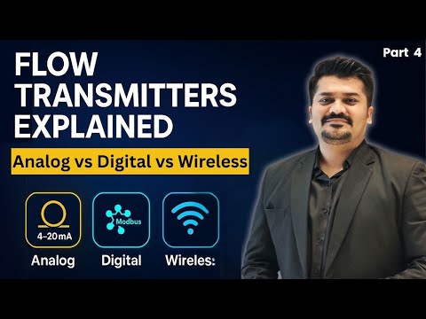
Modern electromagnetic flowmeter transmitters don’t just output a flow reading. They continuously monitor their own health and generate diagnostic alarms that — when read and acted upon — can prevent 80% of field failures before they affect measurement accuracy.
The problem is that most diagnostic alarms go unread. The HART port on the transmitter is connected but no one has a HART communicator. The Modbus register for electrode impedance exists but isn’t mapped to the SCADA historian. The empty-pipe detection alarm triggered six months ago and was acknowledged by the DCS operator but never investigated.
Interpreting Common Diagnostic Alarms
| Alarm Code | What It Means | Typical Cause | Immediate Action |
|---|---|---|---|
| Empty pipe / low-fill | Sensor detects the pipe is not full | Low process level, pump cavitation, improper installation at high point | Check process level; confirm installation orientation |
| Electrode fault | Electrode impedance out of normal range | Coating (high impedance) or short (low impedance) | Read actual impedance value; schedule cleaning if >100 kΩ |
| Coil fault | Coil drive circuit out of specification | Coil insulation degradation, wiring resistance | Measure coil resistance against datasheet; escalate to manufacturer |
| Low excitation | Magnetic field strength reduced | Power supply issue, coil problem | Check power supply voltage at transmitter; check coil resistance |
| Ground fault | Grounding resistance exceeds threshold | Corroded grounding ring, broken ground conductor | Measure fluid-to-earth resistance; inspect and clean/replace grounding hardware |
| Signal overflow | Induced voltage exceeds measurement range | Excessive flow velocity (over-range) | Check actual flow rate; confirm meter sizing is correct |
| Configuration error | Parameter outside valid range | Transmitter reconfigured incorrectly | Compare current configuration against commissioning baseline |
Using HART and Modbus for Remote Health Monitoring
HART (Highway Addressable Remote Transducer): Superimposes digital data on the standard 4-20 mA signal. Even without replacing existing wiring, a HART-capable host or handheld communicator can access electrode impedance, coil drive current, zero stability, and diagnostic alarm status — all from the control room or field device management software.
For EPC projects and utility operators managing large meter populations, HART multiplexers allow continuous monitoring of diagnostic data from hundreds of meters simultaneously, with automated alerts when any parameter exceeds defined thresholds.
Modbus RTU/TCP: Direct digital communication where the meter transmits all measured variables and diagnostics to a PLC or SCADA system on request. For new plant designs and DCS integration projects, Modbus (or PROFIBUS for legacy DCS platforms) provides the richest diagnostic data stream.
For the full communication protocol reference and SCADA integration guidance, the analog vs. digital flow meter comparison guide maps every output type — 4-20 mA, HART, Modbus, PROFIBUS — against their integration requirements and limitations.
Integrating Flowmeter Diagnostics Into SCADA and DCS Platforms
The value of diagnostic data is zero if it stays in the transmitter. The practical implementation steps for EPC and system integrators:
- Map diagnostic registers in the I/O list during design — electrode impedance, coil status, empty-pipe flag, ground fault status — before the control system is configured
- Set alarm thresholds in the DCS for each critical parameter: electrode impedance > 80 kΩ = maintenance alert; empty pipe detection = process alarm
- Configure trending for key diagnostics — electrode impedance trended over 12 months shows coating buildup rate, allowing maintenance planning before accuracy is affected
- Create maintenance reports that display diagnostic trends alongside calibration records, enabling data-driven calibration interval decisions
Сайт intelligent electromagnetic flow meter from Jade Ant Instruments supports simultaneous 4-20 mA, pulse, HART, and Modbus RS-485 output with built-in self-diagnostics including empty-pipe detection, electrode impedance monitoring, and coil drive status — documented to integrate with Siemens S7, Allen-Bradley ControlLogix, ABB 800xA, and Honeywell Experion DCS platforms.
9. Calibration Frequency by Application — Practical Reference
The following table is the practical calibration scheduling reference for MRO teams and utility operators managing electromagnetic flowmeter populations across different service types:
| Заявка | Fluid | Проверка на месте | Bench Calibration | Key Driver |
|---|---|---|---|---|
| Municipal water billing | Clean potable water | Every 12–24 months | Каждые 3–5 лет | Revenue protection, regulatory (OIML R49) |
| Wastewater treatment | Raw / treated sewage | Every 6–12 months | Каждые 2–3 года | Biological fouling rate |
| Chemical process dosing | Acids, bases, solvents | Every 6–12 months | Every 1–2 years | Batch accuracy, liner/electrode corrosion |
| Pharmaceutical process | WFI, purified water, CIP | Every 3–6 months | Every 12 months | FDA GMP compliance (21 CFR Part 211) |
| Mining / mineral slurry | Tailings, concentrate | Every 3–6 months | Every 6–12 months | Severe abrasion; rapid electrode wear |
| Food & beverage production | Milk, juice, beer | Каждые 6 месяцев | Every 1–2 years | Biological fouling; hygienic compliance |
| HVAC / chilled water | Treated glycol / water | Every 24 months | Every 5 years | Low fouling; non-critical monitoring |
| Irrigation / agriculture | Canal water, effluent | Every 12–24 months | Каждые 3–5 лет | Moderate fouling; seasonal operation |
💡 Interval adjustment rule: Shorten the calibration interval if three consecutive verifications show as-found errors above 0.3%, or if transmitter diagnostics show a trending increase in electrode impedance between verifications. Lengthen the interval if three consecutive calibrations show as-found errors within 0.15% and diagnostics show stable parameters.
10. When to Repair, Replace, or Upgrade: A Decision Framework
At some point, every electromagnetic flowmeter faces a decision: invest in repair, replace with a comparable unit, or upgrade to a better-specification instrument. Making that decision on purchase price alone is almost always wrong.
Assessing Lifespan and Wear Indicators
Electromagnetic flowmeters don’t have a fixed service life — but they do have wear indicators that signal when end-of-life is approaching:
| Wear Indicator | Threshold Requiring Action | Typical Service Life Under Normal Conditions |
|---|---|---|
| Liner condition | Cracking, delamination, swelling | 15–20 years (PTFE); 8–12 years (rubber, aggressive service) |
| Electrode corrosion | Pitting visible; impedance permanently > 200 kΩ after cleaning | 10–20 years depending on fluid chemistry |
| Coil insulation resistance | < 20 MΩ at 500V megohm test | 15–25 years in enclosed, dry installations |
| Transmitter electronics | Repeated board failures; firmware no longer supported | 10–15 years; obsolescence risk increases after year 10 |
The Repair vs. Replace Decision — The 50% Rule Applied to Flowmeters
The general industry guideline: if the cost of repair exceeds 50% of the cost of a comparable replacement unit, replacement is almost always the better financial decision. But the comparison must be against like-for-like replacement — the same measurement performance and service life expectation.
| Сценарий | Recommended Action | Reasoning |
|---|---|---|
| Electrode fouling, liner intact, transmitter healthy | Clean and recalibrate | Low cost; meter has years of life remaining |
| Electrode pitting beyond cleaning, liner intact | Replace sensor only | Liner replacement more expensive than electrode swap |
| Liner failure (delamination, cracking) | Full meter replacement | Liner replacement cost approaches new meter cost |
| Transmitter failure, sensor healthy, model obsolete | Upgrade transmitter to digital/HART-capable model | Sensor remains; new transmitter adds SCADA integration capability |
| Chronic grounding problems on plastic pipe | Add grounding rings; recalibrate | $200 fix that resolves $3,000/year in service calls |
| Age > 15 years; repeated failures; poor diagnostics | Full replacement with modern diagnostic-capable meter | TCO favors replacement; upgrade enables predictive maintenance |
Upgrading Legacy Analog Systems to Digital Communication
A large population of electromagnetic flowmeters in service today — particularly in municipal water and wastewater networks installed before 2010 — output only a standard 4-20 mA analog signal with no HART or Modbus capability. These meters cannot report diagnostic data, electrode status, or empty-pipe conditions. They can only report flow rate, and only when someone reads the 4-20 mA value.
For MRO teams and utility operators managing aging infrastructure, the upgrade path is typically to retain the sensor body (if liner and electrodes are in good condition) and replace only the transmitter with a modern digital-output model. This provides SCADA integration, real-time diagnostics, and data logging at typically 40–60% of the cost of full meter replacement.
For the complete financial comparison of repair vs. replacement with documented TCO calculations, the flow meter decision tree guide for non-engineers from Jade Ant Instruments includes a worked example showing why a “more expensive” meter is often $3,400 cheaper over a 10-year service life.
Installation Quality vs. Measurement Accuracy — Field Data Summary
The following table summarizes the measurement accuracy impact of the most common installation and maintenance errors, based on field service data:
| Error Type | Typical Accuracy Impact | Time to Detect | Typical Repair Cost |
|---|---|---|---|
| Missing grounding rings (plastic pipe) | ±4–12% reading error | Days to months | $50–$200 (rings + installation) |
| Signal cable routed with VFD power cable | ±2–8% oscillation | Immediate | $100–$400 (rerouting + shielded cable) |
| Electrode coating (early stage, 50–100 kΩ) | ±0.5–2% low reading | Weeks to months | $200–$800 (cleaning + recalibration) |
| Недостаточная длина прямого участка перед сужением | ±1–3% systematic bias | Immediate; often blamed on meter | $500–$5,000 (flow conditioner or relocation) |
| Air pocket at measurement point | ±2–10% erratic high readings | Condition-dependent | $300–$2,000 (relocation) |
| Zero not recalibrated after installation | ±0.1–0.5% systematic bias | Months to years | $150–$400 (recalibration) |
| Electrodes at 12/6 o’clock horizontal | Gas bubble interference | Condition-dependent | $500–$2,000 (meter rotation or relocation) |
11. Empowering Your Operations With Expert Troubleshooting Knowledge

For OEM manufacturers, system integrators, and maintenance teams, electromagnetic flowmeter troubleshooting mastery means two things: solving problems faster when they occur, and preventing most of them from occurring at all.
The data in this guide points clearly: 58% of all field failures originate in grounding and electrode fouling — both entirely preventable with correct installation and scheduled maintenance. The remaining failures divide between wiring damage (correctable with proper cable management), zero-offset drift (caught by annual calibration), coil degradation (detected by transmitter diagnostics), and liner or transmitter faults (addressed by TCO-based replacement decisions).
The professionals who apply this framework — systematic grounding verification at commissioning, electrode impedance monitoring as part of routine maintenance, calibration intervals justified by actual drift history rather than arbitrary schedules, and SCADA integration of diagnostic data — reduce service callbacks by 60–80% and extend meter service life by 5–10 years in documented field programs.
Your three immediate action items:
1. Verify grounding on every electromagnetic flowmeter installed on a non-metallic pipe. Use a multimeter. Check fluid-to-earth resistance. If it’s above 10 Ω, install grounding rings before the next calibration event.
2. Enable and map diagnostic data from every HART-capable transmitter to your SCADA historian. Electrode impedance trending costs nothing to configure and gives early warning of the two most common failure modes.
3. Review calibration intervals against this guide’s application matrix. If your current schedule is driven by calendar rather than risk, three calibrations at the correct interval will show whether that interval is appropriate — and give you documented evidence to adjust it in either direction.
For technical consultation on specific installation problems, calibration planning, or OEM customization requirements for electromagnetic flowmeters, visit Инструменты "Нефритовый муравей or review the magnetic flow meter maintenance best practices guide for the full preventive maintenance workflow.
Frequently Asked Questions About Electromagnetic Flowmeter Troubleshooting
Written for engineers, MRO buyers, EPC project teams, and utility procurement specialists — concrete answers, no filler.
Q1: Why is my electromagnetic flowmeter showing fluctuating readings in an otherwise stable process?
Start with grounding and EMI — they account for the majority of this symptom. Confirm grounding ring installation and measure fluid-to-earth resistance (target < 10 Ω). Check that signal cables are routed separately from power cables and VFD wiring. If grounding and EMI are confirmed correct, check electrode impedance via the transmitter diagnostics — values above 100 kΩ indicate coating that’s attenuating the signal. Empty pipe is also a possibility: confirm the pipe is full at the measurement point by checking the transmitter’s empty-pipe detection alarm status.
Q2: Can I use an electromagnetic flowmeter for deionized water?
Standard electromagnetic flowmeters require a minimum conductivity of approximately 5 μS/cm. Deionized water typically falls below 1 μS/cm — well below this threshold. The transmitter will produce erratic or zero readings, not because it’s defective but because the fluid cannot carry enough electrical charge to generate a detectable induced voltage. For deionized water, ultra-pure water, and WFI (Water for Injection) pharmaceutical applications, the appropriate alternatives are Coriolis meters (which measure mass flow independent of fluid electrical properties) or specialized high-sensitivity electromagnetic meters rated for operation below 5 μS/cm — confirm the exact model specification before procurement.
Q3: How often should I calibrate my electromagnetic flowmeter in a continuous process?
For most continuous industrial applications, in-situ verification every 12 months and bench calibration every 2–3 years is the starting baseline. Accelerate to every 6 months for wastewater, pharmaceutical, or high-fouling applications. Extend to every 3–5 years only for clean utility water in non-critical monitoring service, and only when three consecutive calibrations have confirmed as-found errors within 0.15%. Never extend calibration intervals without documented historical performance data — the interval should reflect actual meter behavior, not budget convenience.
Q4: What are the signs of electrode coating, and how do I fix it?
The early warning signs are: zero drift when the pipe is full and confirmed stationary (zero should read 0.000 ±0.05% FS); increasing noise or oscillation during steady-flow periods; and a systematic low-reading bias that grows over weeks or months. Confirm by reading electrode impedance from the transmitter diagnostics — values above 50 kΩ indicate early coating; above 100 kΩ the reading is likely affected. Clean with the appropriate agent for the deposit type (citric acid for calcium scale, alkaline cleaner for biofilm, neutral detergent for wax) after confirming compatibility with the liner and electrode materials. For recurrent coating in municipal wastewater or scaling water service, specify self-cleaning electrode designs or capacitive non-contact electrodes for the next meter purchase.
Q5: Do I need grounding rings in plastic or lined pipes?
Yes — without exception. Plastic pipes (HDPE, PVC, GRP), FRP pipes, and epoxy-lined steel pipes are electrical insulators. The process fluid floating electrically inside an insulating pipe has no electrical reference point for the transmitter. The result is measurement noise that appears identical to EMI interference but cannot be resolved by any amount of cable shielding or transmitter configuration. Install 316L stainless steel grounding rings on both flanges (upstream and downstream) and connect them to the meter body with a 4mm² conductor tied to the plant earth bus. Confirm fluid-to-earth resistance below 10 Ω at commissioning.
Q6: Why does my flowmeter read zero even when fluid is flowing?
Check these in sequence: (1) Is the empty-pipe detection active? If the conductivity or fill level is below threshold, many transmitters output zero rather than an erratic reading as a safety feature — check if the empty-pipe alarm is latched in the transmitter. (2) Is the power supply correct? Confirm 24VDC or 85-264VAC at the terminals. (3) Is the 4-20 mA loop complete? A broken loop (open circuit at the control system input) will read 0 regardless of the transmitter output. (4) Are the electrodes shorted? An electrode impedance below 0.5 kΩ suggests a conductive deposit bridging the electrodes or a damaged liner. (5) Has the transmitter been configured with a low-flow cutoff that’s set too high? Some transmitters cut output to zero below a configurable velocity threshold — check this setting against your actual minimum flow.
Q7: Can VFDs affect my electromagnetic flowmeter’s performance?
Yes — VFDs are one of the most common sources of flowmeter signal noise in industrial plants. They generate high-frequency switching noise (typically 1–20 kHz) from their PWM output stages that couples into nearby instrument cables capacitively and inductively. The effect is reading oscillations that correlate with motor load changes and pump speed variation. Mitigation in order of effectiveness: (1) Re-route signal cables to a dedicated instrument cable tray with 300mm minimum separation from VFD power cables; (2) Replace with manufacturer-specified double-shielded twisted-pair cable; (3) Add ferrite chokes on signal cables within 150mm of the transmitter terminal box; (4) Verify shield is grounded at transmitter end only; (5) If all else fails, install an EMC filter on the VFD power supply input. All five measures are documented with worked installation examples in Control Engineering’s EMI guide for drive users.
Q8: What is the minimum straight pipe length required upstream of an electromagnetic flowmeter?
The minimum upstream straight run is typically 5D (five times the pipe inner diameter) after a single 90° elbow, increasing to 10D after two elbows in the same plane and 15–20D after two elbows in perpendicular planes. After a partially open control valve, allow at least 20D — and ideally avoid installing downstream of a partially open valve entirely. Downstream requirements are 2–3D after the meter. These are manufacturer minimums — installing at exactly minimum leaves no safety margin for installation deviations. In constrained spaces, flow conditioners (perforated plate, tube bundle, or vane-type) can reduce upstream requirements by 40–60%.
Q9: How do I verify if my electromagnetic flowmeter is properly grounded?
Use a calibrated multimeter with the process running (pipe full). Measure resistance between the grounding ring (or meter body flange) and the plant instrument earth bus. The reading must be below 10 Ω for adequate grounding. A reading above 100 Ω indicates a corroded or broken earth connection. A reading in the megohm range confirms the grounding ring is not making electrical contact with the fluid — typically because the grounding ring gasket is non-conductive, the ring is installed with the wrong orientation, or the pipe material is preventing contact. Also measure AC voltage between the meter body and plant earth: above 100 mV AC suggests a ground potential difference that will cause noise.
Q10: Can I troubleshoot an electromagnetic flowmeter without shutting down the process?
Yes — modern transmitters with HART, Modbus, or PROFIBUS communication allow full diagnostic access without process interruption. Using a HART communicator or AMS Device Manager, you can read electrode impedance, coil drive current, zero stability, ground fault status, and empty-pipe detection — all while the process continues running. Zero verification requires closing block valves (a brief shutdown of that measurement point), but this can often be planned to coincide with normal process hold periods. Physical inspection of grounding rings and cable entry points can be performed during normal operation. Reserve full process isolation for electrode cleaning or sensor removal — both of which require the measurement point to be bypassed or the process to be stopped.
Q11: What liner material is best for abrasive slurries?
Ceramic (aluminium oxide, Al₂O₃) is the correct choice for high-abrasion applications where the slurry contains hard particles — mining tailings, coarse mineral concentrates, titanium dioxide, cement slurry. Its Vickers hardness of approximately 1,700 HV is more than 10 times harder than rubber (35 Shore A equivalent). In documented copper concentrator service, ceramic-lined meters achieved 11-year liner life against 18–24 months for the rubber-lined meters they replaced. Polyurethane is the cost-effective alternative for moderate abrasion — effective in dredging, wastewater screening, and mineral processing where solids content is moderate and particle hardness is lower than hard rock mineral service.
Q12: Why is my electromagnetic flowmeter failing prematurely in a wastewater treatment plant?
Wastewater environments are uniquely aggressive for electromagnetic flowmeters because they combine biological fouling on electrodes, chemical attack from chlorination and dosing chemicals, abrasion from grit and fiber, and the moisture-rich environment that accelerates corrosion on grounding connections and cable entries. The three most common root causes of premature failure in wastewater service are: (1) Rubber liner attacked by chlorination chemistry above 300 ppm — specify PTFE or PFA instead; (2) 316L stainless electrodes corroded by sulfides or chlorides — specify Hastelloy C-276; (3) Biological slime on electrodes causing gradual impedance increase and reading drift — implement quarterly electrode inspection and cleaning as a scheduled maintenance item, not a reactive one.
Q13: Can I integrate an older analog-only electromagnetic flowmeter with a modern SCADA system?
Yes — via a HART modem or protocol converter. If the existing meter outputs only 4-20 mA, two integration paths are available: (1) For meters with a HART communication layer (even if the HART port has never been used), a HART multiplexer or HART modem converts the HART digital data to Modbus or OPC-UA for SCADA integration without replacing any hardware; (2) For genuinely analog-only meters with no HART capability, a 4-20 mA to Modbus converter ($150–$400) bridges the analog signal to a digital SCADA network. Neither approach recovers diagnostic data that the transmitter isn’t generating — only a transmitter upgrade provides access to electrode status, coil health, and empty-pipe alarms.
Q14: Is it necessary to recalibrate an electromagnetic flowmeter after relocating it?
Yes. Relocation changes the following conditions that directly affect calibration: installation orientation (vertical vs. horizontal; upward vs. downward flow) alters how gravity affects the fluid profile across the electrodes; pipe size and material at the new location may be different, changing the grounding configuration; upstream piping geometry at the new location differs from the previous installation, affecting flow profile; and the process fluid at the new location may have different conductivity, temperature, or chemistry. Perform a complete zero check and multi-point flow verification at the new installation before putting the meter back in service.
Q15: How do temperature changes affect electromagnetic flowmeter accuracy?
Temperature affects electromagnetic flowmeters through three mechanisms: (1) Liner thermal expansion — PTFE expands approximately 12× more than steel at temperature. On a PTFE-lined meter that cycles between 20°C and 120°C repeatedly, progressive dimensional change at the electrode seal face can shift zero offset by 0.1–0.5% over years; (2) Electronic drift — transmitter analog circuits drift with temperature cycling; high-quality transmitters compensate this electronically, but budget transmitters may not; (3) Fluid conductivity changes — conductivity increases approximately 2% per °C for most ionic solutions. If the transmitter is not temperature-compensating the conductivity, a fluid that just meets the 5 μS/cm threshold at 20°C may fall below it at cold startup in winter conditions. For installations with large temperature swings (>50°C), specify meters with temperature compensation in the transmitter and confirm the liner thermal expansion rating against your actual temperature cycle.
Glossary of Key Technical Terms
Calibration Drift: A gradual, systematic shift in a flowmeter’s reading relative to true flow value, caused by electrode coating, electronic aging, or grounding degradation. Invisible without scheduled verification.
Coil Drive Current: The electrical current supplied to the electromagnetic coils that generate the magnetic field inside the meter. Specified in milliamps; a reading outside ±5% of specification indicates coil or wiring problems.
Electrode Impedance: The electrical resistance at the interface between the electrode face and the process fluid. Measured in kilohms (kΩ). Normal: 1–50 kΩ. Above 100 kΩ indicates coating.
EMI (Electromagnetic Interference): Unwanted electrical noise from motors, VFDs, welding equipment, or power cables that corrupts the millivolt-level signal from the electrodes.
HART (Highway Addressable Remote Transducer): A digital communication protocol superimposed on a 4-20 mA analog signal. Enables remote diagnostic data, configuration, and secondary variable transmission without additional wiring.
Grounding Ring: A conductive ring installed between the meter and pipe flanges on both sides, providing direct electrical contact between the process fluid and the plant earth bus. Mandatory on non-metallic pipes.
In-Situ Verification: Checking meter accuracy while it remains installed in the process pipe, using built-in transmitter diagnostics and/or an independent reference flow measurement.
IP Rating: Ingress Protection rating for electronic enclosures. IP67 = dust-tight and submersible to 1 meter for 30 minutes. IP68 = rated for continuous submersion.
Liner: The inner surface of the electromagnetic flowmeter tube that contacts the process fluid. Must be chemically compatible, temperature-rated, and mechanically suitable for the service.
Pulsed-DC Excitation: The modern standard for generating the magnetic field in an electromagnetic flowmeter — uses a low-frequency alternating square wave rather than AC power, reducing electrode polarization and power consumption.
TAR (Test Accuracy Ratio): The ratio of calibration reference accuracy to meter accuracy. Standard requirement: 4:1. For a 0.5% meter, the reference must be at least 0.125% accurate.
TCO (Total Cost of Ownership): All costs over a meter’s service life — purchase, installation, calibration, maintenance, spare parts, and downtime risk. The number that matters for capital justification.
VFD (Variable Frequency Drive): An electronic drive that controls motor speed by varying the power supply frequency. A major source of EMI in industrial plants, particularly affecting nearby instrument signal cables.
Zero Offset: A non-zero reading from the transmitter when the pipe is full of stationary fluid and true flow is confirmed at zero. Should be 0.000 ±0.05% FS; values outside this range require zero adjustment.
For application-specific troubleshooting support, electromagnetic flowmeter calibration services, and OEM integration consultation, visit Инструменты "Нефритовый муравей or review the top magnetic flowmeter applications guide for field performance data across water, chemical, wastewater, pharmaceutical, and mining sectors.
Technical References:
- Soaring Instrument — What Causes Errors in a Magnetic Flow Meter (2024 Field Analysis)
- Endress+Hauser — Best Practices for Flow Calibration Management
- KEB America — VFD EMI: Causes, Effects and Practical Solutions
- Faraday’s Law of Electromagnetic Induction — Wikipedia
- ATEX Equipment Directive — European Commission
- Flow Measurement Compliance — U.S. EPA