Executive Insight: Why Flow Measurement Matters in Skid-Based Systems

Skid-mounted systems — pre-assembled, self-contained process packages built in a controlled shop environment and then shipped to site — have become the dominant delivery model for OEM equipment builders worldwide. From chemical injection skids on offshore platforms to packaged water treatment systems serving municipal utilities, the pressure to deliver commissioning-ready, fully tested packages has never been higher.
Inside every one of those skids sits at least one flow meter. In many cases, there are four, six, or more. The choice of meter technology directly affects three things that keep project managers awake at night: commissioning schedule, ongoing maintenance cost, and system accuracy. Choose the wrong technology, and a $500 meter selection error can cascade into a $50,000 warranty call six months after installation.
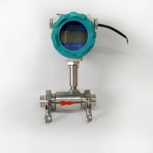
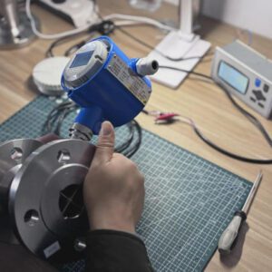
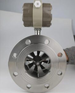
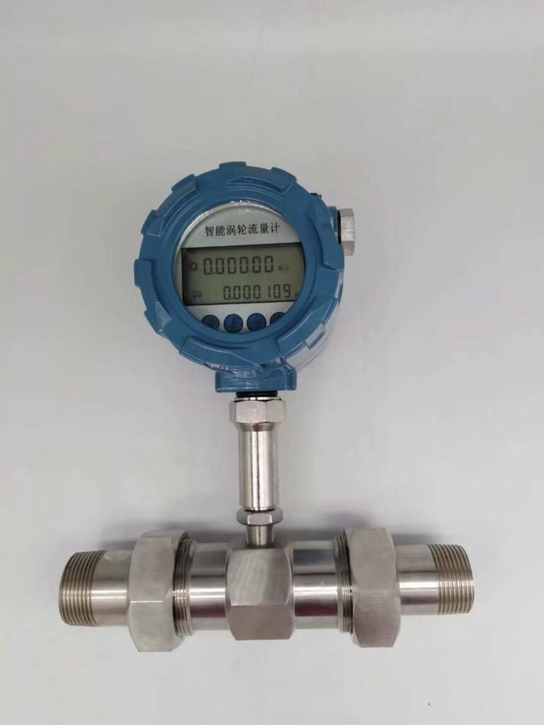
Turbine flow meters — devices that measure volumetric flow by counting the rotations of a precision-machined rotor spinning in the fluid stream — have served OEM skid builders, instrument distributors, EPC integrators, and industrial end users for decades. The global flow meter market is projected to grow from USD 12.14 billion in 2026 to USD 19.46 billion by 2034, driven by expanding automation, tightening process accuracy requirements, and the continued construction of packaged process systems across water treatment, oil and gas, chemical processing, and food & beverage industries (Fortune Business Insights).
Within that market, turbine meters occupy a unique position: they deliver laboratory-grade accuracy at a fraction of the cost of Coriolis or multi-path ultrasonic technology, install into standard piping without extensive straight-run requirements, and produce clean digital pulse signals that PLCs and SCADA systems read natively. This guide examines the five specific performance benefits that make turbine flow meters a rational, defensible choice for the engineering teams and procurement managers who specify flow instrumentation in skid-based systems.
Benefit #1: Superior Accuracy for Consistent Process Control

What “Accuracy” Actually Means in a Skid Context
When an instrument data sheet lists ±0.5%の読み取り値 accuracy, it means the meter’s output will stay within half a percent of the actual flow value across the entire calibrated flow range. That is a meaningfully different — and better — specification than ±0.5% of full scale, a figure that many differential-pressure (DP) meters and rotameters quote. At 20% of full scale flow, a ±0.5% of full-scale error translates to a real-world ±2.5% of the actual reading. For a skid dosing a corrosion inhibitor at low flow rates, that difference is the gap between protecting the asset and wasting expensive chemical.
Premium turbine meters achieve ±0.1% to ±0.25% of reading, which puts them within the accuracy band required for custody transfer and aerospace fuel metering — applications where product value and regulatory compliance demand the tightest measurement possible. For the vast majority of OEM skid applications — fuel blending, chemical injection, water treatment dosing, hydraulic testing — ±0.5%の読み取り値 provides more than adequate accuracy without the premium price of Coriolis or ultrasonic multi-path instruments.
Turndown Ratio: The Number Most Specifiers Underweight
Turndown ratio (also written as rangeability) describes how wide a flow range the meter measures accurately. A meter with a 10:1 turndown ratio that is calibrated for 100 GPM maximum accurately measures flow from 10 GPM to 100 GPM. Below 10 GPM, accuracy degrades. Turbine meters routinely achieve 20:1 to 50:1 turndown on clean liquids, with specialized low-flow designs reaching 100:1.
This matters for skid builders because process conditions are rarely static. A chemical injection skid operating at full capacity runs very different flow rates than the same skid running at 15% during startup or standby. An orifice plate — the lowest-cost DP meter — typically offers only 3:1 to 5:1 turndown. Specifying an orifice plate on a skid where flow varies by 20:1 during normal operation is a specification error that creates a support problem the first time a customer calls to report inaccurate dosing at low load.
What This Looks Like in Practice
A Midwest chemical blending OEM building corrosion inhibitor dosing packages for refinery clients replaced differential-pressure gauges with turbine flow meters on twelve injection skids. The result: batch-to-batch chemical concentration variance dropped from ±4.2% to ±0.6%. That 3.6 percentage point improvement meant 18% less inhibitor consumption per batch — a saving the customer quantified at approximately $23,000 per year across three refineries. The turbine meters paid for themselves in the first month of operation.
For distributors representing a turbine meter product line, this is the kind of outcome data that closes deals: not “the meter is accurate” but “the customer saved $23,000 in the first year and we can show the before-and-after data.”
Accuracy vs. Technology Comparison
| テクノロジー | 標準精度 | ターンダウン率 | 最適 |
|---|---|---|---|
| Turbine Flow Meter | ±0.1% – ±0.5% of reading | 20:1 – 100:1 | Clean liquids, gases, precision batching |
| Coriolis Flow Meter | ±0.1% – ±0.2% of reading | 100:1+ | Mass flow, mixed-phase, custody transfer |
| Electromagnetic (Mag Meter) | ±0.2% – ±0.5% of reading | 30:1 – 100:1 | Conductive liquids, slurries, zero moving parts |
| オリフィスプレート (DP) | ±0.5% – ±2% of full scale | 3:1 – 5:1 | Steam, high-temp gas, low-cost water |
| Variable Area (Rotameter) | ±2% – ±5% of full scale | 10:1 | Visual indication, very low flow |
| 渦流量計 | ±0.5% – ±1% of reading | 20:1 – 40:1 | Steam, gas, clean liquids above minimum velocity |
Data compiled from manufacturer datasheets and KOBOLD USA Turbine Flow Meter Guide.
Benefit #2: High Flow Rate Capability with Minimal Pressure Drop

Why Pressure Drop Is a Skid Engineering Problem, Not Just a Meter Spec
Every flow meter installed in a pipeline creates resistance to flow, which engineers call pressure drop (also written ΔP or pressure differential). Pressure drop is paid for twice: once during system design, when engineers must specify larger pumps to overcome it, and once every hour the system operates, as higher pump energy consumption adds up on the electricity bill.
In a compact skid layout — where ten to thirty flow measurement points may be packed into a manifold spanning only a few meters — the cumulative pressure drop from multiple instruments can force a costly pump upgrade or, worse, reveal itself only during site commissioning when the system fails to reach design flow rate.
Turbine flow meters create significantly lower pressure drop than the alternatives most commonly compared against them. An orifice plate running at design velocity creates a permanent pressure loss of 0.3 to 1.0 bar depending on the beta ratio. A well-designed turbine meter body at the same flow conditions creates 0.05 to 0.15 bar — roughly one-fifth to one-tenth the loss. For a skid with eight measurement points, that difference can reduce total instrument pressure drop from 4–8 bar to under 1 bar.
The Energy Cost of Pressure Drop Over Ten Years
Consider a DN50 (2-inch) injection skid line running 15 m³/hr continuously. The permanent pressure drop through an orifice plate at this condition is approximately 0.35 bar. Through a turbine meter of equivalent size, it is 0.07 bar — a difference of 0.28 bar. Using the standard pump power formula:
where Q is volumetric flow rate (m³/s), ΔP is pressure differential (Pa), and η is pump efficiency (approximately 0.70), the excess power consumption from the orifice plate versus the turbine meter works out to approximately 250 watts at this condition. Running continuously at an industrial electricity tariff of $0.09/kWh, that is:
Across eight measurement points on one skid running for ten years, the pressure-drop energy penalty of orifice plates versus turbine meters exceeds $15,800. For an EPC firm specifying instrumentation across a project with fifty skids, that figure scales to hundreds of thousands of dollars — costs that will appear in the end user’s utility bills and eventually in a conversation about why the package was “not designed efficiently.”
Relevance for EPC Project Engineers
EPC system integrators who specify flow instruments carry professional responsibility for the hydraulic design of the packages they deliver. Turbine meters give EPC engineers a defensible, documented path to lower system ΔP while maintaining the accuracy required for process guarantees. When a licensor requires ±1.0% or better accuracy on a chemical injection system, the turbine meter delivers that accuracy at one-third the pressure drop of the alternative DP technology. That is a win that shows up in the hydraulic calculation, the energy balance, and the client’s long-term operating cost — all of which EPC firms are increasingly held accountable for under performance-guarantee contracts.
Benefit #3: Fast Response Time for Dynamic Process Environments
Response Time Defined
Response time in flow measurement refers to the time it takes the meter’s output signal to reflect an actual change in flow. It is typically expressed as T90 (the time to reach 90% of the new reading after a step change in flow) or T99 (99% of the new reading). A meter with a T90 of 500 milliseconds will report a new flow value within half a second of an actual change occurring in the pipe.
Turbine meters respond in under 50 milliseconds to flow changes, because the physics are direct: the rotor spins faster within milliseconds of flow acceleration, and the magnetic pickup sensor reports that change as an immediate increase in pulse frequency. There is no averaging, no signal integration delay, and no thermal lag. The rotor is the sensor.
Why This Matters in Automated Skid Control Loops
Modern OEM skids are not just passive measurement packages — they are actively controlled systems. A fuel blending skid uses flow measurement feedback to trim a proportional control valve in real time, maintaining a target ratio between two fuel streams. A chemical dosing system uses flow totalization to trigger a batch close-off valve when a preset volume has been dispensed. In both cases, the speed at which the flow meter reports a change directly determines how precisely the control loop can perform.
A control loop running on a 500-millisecond scan cycle can only benefit from a flow meter that reports accurate values within that window. A meter with a 2-second averaging filter — common in some ultrasonic and Coriolis implementations — feeds the PLC stale data that causes the loop to overshoot or undershoot. The result is measurable: wider batch volume variance, more off-spec product, more trim adjustments, and ultimately more waste.
Turbine meters’ sub-50ms response time means that for most PLC scan rates (100ms to 1000ms), the meter is never the limiting factor in control loop performance. The loop is limited by the valve actuator, the pump response, or the PLC program — not by the sensor.
Solving the Transient Condition Problem
Skid systems frequently experience transient flow conditions — rapid changes in demand during startup sequences, pump changeovers, emergency shutdowns, or batch initiation events. These transients can last only a few seconds but cause significant measurement errors in technologies with slow response or high signal damping.
A water injection skid on an oil platform, for example, may experience a 0–100% flow ramp-up during pump start in under 3 seconds. A slow-responding meter will under-report total injected volume during that ramp, creating a cumulative measurement error that compounds over hundreds of pump start cycles per year. Turbine meters track that ramp accurately from the first rotation, ensuring totalizer accuracy even during high-rate transient events.
Benefit #4: Compact and Modular Design for Seamless Skid Integration

The Physical Reality of Skid Design
OEM skid builders work within a hard physical constraint: the skid frame dimensions are often set by the customer’s available footprint, the shipping container dimensions, or the maximum crane-lift weight. Inside those dimensions, the designer must fit pumps, vessels, control valves, instrumentation, wiring panels, and piping — all while maintaining maintenance access, satisfying code-required spacing, and ensuring the package looks professional enough to reflect well on the OEM’s brand.
Flow meters are installed on the piping, and piping takes space. The critical dimensions are the face-to-face length of the meter body and the upstream straight-run requirement — the length of unobstructed straight pipe required before the meter inlet to ensure a fully developed, non-swirling flow profile reaches the sensing element.
A turbine flow meter in a standard flanged body covers face-to-face lengths from 100mm to 400mm for pipe sizes ½” through 6″. The upstream straight-run requirement is typically 10 to 15 pipe diameters (D), with 5D downstream. For a DN50 (2-inch) line, that is 500–750mm upstream and 250mm downstream — a total piping envelope of approximately 850mm to 1,150mm per measurement point.
Compare that to an electromagnetic flow meter, which requires 5D upstream and 2D downstream (a tighter requirement), or to an ultrasonic clamp-on meter, which requires 10D upstream but adds no face-to-face length since it mounts externally. For skid applications where the fluid is clean and the process requires custody-transfer-grade accuracy, the turbine meter’s compact body and moderate straight-run requirement make it the practical choice.
Standardization Across OEM Product Lines
For OEM skid manufacturers that build the same package design in high volumes — fifty chemical injection skids per year, for example — standardization is the single most powerful cost-reduction lever available. Every time an engineer has to make a new instrument selection decision, evaluate a new vendor, write a new calibration procedure, or source a new spare part, it costs time and money that erodes margin.
Turbine meters enable standardization because they are available in consistent form factors across a wide range of flow rates and pipe sizes from multiple manufacturers including ジェイド・アント・インストゥルメンツ, who support OEM/ODM customization with consistent dimensional interfaces, configurable output signals (pulse, 4–20 mA, Modbus), and volume pricing that rewards repeat orders. A skid OEM that standardizes on a single turbine meter model for all 1″ to 2″ skid piping can simplify procurement to a single part number, reduce spares inventory, and train technicians once rather than repeatedly.
For instrument distributors, the implication is equally direct: stocking a turbine meter range that covers ½” through 6″ in one product family simplifies quoting, reduces warehouse SKU count, and allows the distributor to offer volume-based pricing to OEM accounts without carrying excessive inventory risk.
Value for Distributors: Faster Deployment, Simpler Logistics
Turbine meters ship as a self-contained, calibrated unit with a NIST-traceable calibration certificate included. There is no separate transmitter box to configure, no secondary wiring harness to source, and no site-specific calibration required — the meter arrives ready to install. For distributors serving EPC and OEM clients on project schedules where a missed delivery delays commissioning, the turbine meter’s “install and run” simplicity is a genuine differentiator against technologies that require on-site setup, signal configuration, or process-fluid verification before they will produce a reading.
Benefit #5: Low Maintenance and Long Service Life for Reduced TCO

What “Low Maintenance” Means in Real Operating Cost Terms
Every maintenance event on a process skid has a cost that goes far beyond the spare part. When a flow meter fails or requires scheduled service, the actual expense includes technician labor time (typically $85–$150/hour for an instrument technician), the cost of process shutdown or bypass, the calibration service (if required), the spare part itself, and the documentation time for the work order. A single service event on a packaged skid typically costs $800 to $2,500 in total when all these components are counted.
The question is not whether a turbine meter requires maintenance — it does, periodically — but how often, and whether that maintenance can be performed by in-house staff without specialized tools or a manufacturer service contract.
The Mechanical Reality: Why Turbine Meters Last
A turbine flow meter has one moving part: the rotor. The rotor spins on bearings — typically made from tungsten carbide, ceramic, or in premium models, synthetic sapphire (aluminum oxide single crystal, Vickers hardness approximately 2,200 HV). Sapphire bearings are functionally immune to wear from clean liquids at normal flow velocities. Field data from manufacturers supports service intervals of 3 to 5 years between bearing inspections on well-filtered clean-liquid service, with overall instrument life typically reaching 10年から20年 before any major repair is required.
That 15-year service life, amortized over the purchase price, produces a striking cost-per-year figure. A quality turbine meter purchased for $4,000 and operating for 15 years costs approximately $267 per year of service — a figure cited by Turbines Incorporated. A Coriolis meter costing $12,000 with annual calibration costs of $400 and a realistic service life of 12 years carries an amortized cost closer to $1,033 per year — nearly four times higher for applications where the additional accuracy of Coriolis adds no measurable process benefit.
10-Year Total Cost of Ownership Comparison
The table below models the 10-year TCO for three representative flow meter technologies in a typical 2-inch clean-liquid skid application, using conservatively estimated data from publicly available sources.
| 費用区分 | Turbine Flow Meter | Coriolis Flow Meter | オリフィスプレート (DP) |
|---|---|---|---|
| Initial purchase price | $2,500 | $9,500 | $800 |
| Installation labor | $600 | $900 | $700 |
| Calibration (2 events / 10 yr) | $700 | $1,600 | $400 |
| Bearing/rotor inspection (2×) | $350 | $0 | $0 |
| Transmitter/electronics repair | $400 | $1,200 | $600 |
| Downtime incidents (est. 1×) | $1,200 | $800 | $2,500 |
| 10-Year Total TCO | $5,750 | $14,000 | $5,000 |
| Annualized cost/year | $575 | $1,400 | $500 |
| Accuracy (of reading) | ±0.5% | ±0.2% | ±1–2% FS |
Note: Orifice plate TCO appears lowest but does not account for energy costs from pressure drop (adds $150–$500/yr per point at typical industrial electricity rates) or the accuracy degradation below 30% of full scale flow — both of which are significant in variable-load skid applications.
A Real-World MRO & Utility Case: $37,000 Saved in Year One
A municipal water authority operating a regional distribution network replaced nineteen aging turbine meters — original steel-bodied units from the mid-1990s — with modern sapphire-bearing turbine meters featuring onboard Modbus communication. The previous generation of meters had required an average of 2.3 service events per meter per year due to bearing wear, impeller fouling from unfiltered distribution water, and transmitter failures.
After installation of the new generation meters with upstream strainer baskets (added at $180 each) to protect the bearings, the authority recorded zero unscheduled maintenance events in the first twelve months across all nineteen meters. At a conservatively estimated $1,950 per service event (labor + parts + documentation), the elimination of the previous year’s 44 service events saved $85,800 in maintenance labor alone. Subtracting the cost of the new meters and strainers yielded a first-year net saving of approximately $37,000, with the meters expected to run for 12 to 15 years before the next major service.
Application Spotlight: Real-World Use Cases Across Industries
Fuel Blending and Custody Transfer Skids
Petroleum product blending — mixing base stocks, additives, and oxygenates to produce finished fuels — requires flow measurement accurate enough to guarantee product specifications while minimizing valuable component waste. Turbine meters certified to API MPMS 第5章 (the standard governing turbine meters for hydrocarbon measurement) provide the accuracy and repeatability that major oil companies require for custody transfer on product receipt and dispatch skids.
A Gulf Coast skid OEM building packaged additive injection systems for three major oil majors standardized on 1″ and 2″ turbine meters for all liquid additive streams. The standardization reduced the number of calibration service providers they were required to manage from six to two, cut spare parts inventory value by 31%, and allowed the shop to build and test skids 18% faster through familiar installation procedures.
Chemical Injection Packages for Offshore Platforms
Chemical injection on offshore platforms — injecting corrosion inhibitors, scale inhibitors, demulsifiers, and biocides at precise dosing rates into production flowlines — is one of the most technically demanding OEM skid applications. Flow rates are low (often 1 to 50 LPH), pressures are high (up to 700 bar on some platforms), and the cost of a measurement error is a failed corrosion-inhibitor treatment that allows a production flowline to corrode internally — a remediation that can cost $10–$50 million.
Precision turbine meters in PEEK or 316 stainless steel bodies with sapphire bearings are the industry standard for high-pressure chemical injection metering. Their ±0.5% of reading accuracy at 5:1 turndown provides sufficient measurement quality for dosing verification, and their compact body fits into the dense piping manifolds typical of offshore injection packages. Manufacturers like ジェイド・アント・インストゥルメンツ offer turbine meters configured with high-pressure body options and intrinsically safe transmitters for Zone 1 hazardous area certification — a combination that eliminates the need to source body and electronics from two different vendors.
Packaged Water Treatment Systems for Municipal Utilities
Municipal water treatment utilities purchasing pre-packaged chemical dosing systems for chlorination, fluoridation, pH correction, and coagulant addition specify turbine meters to measure chemical feed rates with the accuracy required for regulatory compliance. The EPA’s National Primary Drinking Water Regulations set maximum contaminant levels for disinfection byproducts that are directly tied to chlorine dosing accuracy — a real-world compliance driver that makes meter accuracy a regulatory issue, not just an operational preference.
For instrument distributors selling into the municipal water market, turbine meters offer a clear value proposition: they are widely understood by plant operators and maintenance staff, they carry NIST-traceable calibration certificates that satisfy state regulatory audit requirements, and they are available in materials (PVC, PVDF, 316SS) compatible with the aggressive chemicals used in water treatment.
Hydraulic Test Benches and OEM Test Skids
Turbine meters are the instrument of choice for hydraulic test benches because the application requires high accuracy, fast response, and broad flow range simultaneously. A test bench qualifying hydraulic actuators or control valves must measure flow accurately enough to detect a 2% performance deviation, respond quickly enough to capture transient events during opening and closing cycles, and cover the full flow range of the device under test in a single meter range.
A single DN25 (1-inch) turbine meter with a 30:1 turndown covers a flow range from approximately 1 LPM to 30 LPM — wide enough to test most hydraulic actuators without range switching. The sub-50ms response time captures transient events that slower technologies would average out, ensuring that a valve with a sluggish opening profile is identified during factory acceptance testing rather than after installation on the customer’s equipment.
Selection and Integration Guidance for Engineers and Specifiers
Fluid Compatibility: The First Filter
Turbine meters are optimized for clean, low-viscosity liquids and gases. The rotor bearings require adequate lubrication from the flowing fluid — which means fluids with viscosity below approximately 10 centistokes (cSt) work well, while heavier oils, glycols, and viscous polymers require a viscosity correction factor or a different meter technology entirely. For fluids above 40 cSt, consult the meter manufacturer’s viscosity curves and expect accuracy degradation at higher viscosity.
Fluids containing solid particles — scale, pipe debris, fibrous materials — will accelerate bearing wear. The standard mitigation is to install a 40-mesh (400 micron) strainer upstream of the meter. The strainer costs $50–$200 and protects a $2,500+ meter from premature bearing failure. This is a detail that instrument distributors should communicate proactively to every customer who purchases a turbine meter for a water or process fluid application — it is the single most effective way to prevent the warranty calls that damage distributor reputation.
Straight-Run Requirements
Turbine meters require a developed, non-swirling velocity profile at the meter inlet. The standard requirement is 10 pipe diameters (10D) of straight run upstream そして 5D下流 from the nearest flow disturbance (elbow, valve, reducer, or pump outlet). For installations immediately downstream of a double-elbow-out-of-plane configuration, increase upstream straight run to 20D or install a flow conditioner.
For compact skid layouts where 10D is not physically achievable, dual-rotor turbine meters (where the second rotor acts as both a flow conditioner and a verification reference) can reduce the straight-run requirement to 5D upstream while maintaining accuracy. This is worth discussing with the meter manufacturer during the early design stage, before the piping layout is frozen.
Output Signal Selection for PLC and SCADA Integration
The turbine meter’s native output is a frequency pulse signal — each pulse represents a discrete volume of fluid passing through the meter. The pulse K-factor (pulses per unit volume) is determined during factory calibration and is unique to each meter. This pulse output connects directly to a PLC high-speed counter input with no signal conditioning required, making it the simplest possible integration for basic flow totalization and rate display.
For installations requiring 4–20 mA analog output (for compatibility with legacy DCS systems or analog panel meters), a flow transmitter or signal conditioner converts the pulse frequency to a proportional current. For SCADA integration requiring digital communication, turbine meters paired with smart transmitters support Modbus RTU, HART, and Ethernet/IP protocols — options that transmit not just flow rate but also totalizer value, alarm status, and diagnostic information across a single cable pair.
The table below summarizes the available output options and their typical applications:
| 出力タイプ | Signal Format | Best Used For | Integration Complexity |
|---|---|---|---|
| Pulse (Frequency) | Digital pulses, 1–10,000 Hz | PLC high-speed counter, batch control | 極めて低い |
| 4–20 mA Analog | 4 mA = 0 flow, 20 mA = max flow | Legacy DCS, analog indicators | 低 |
| HART (overlay) | Digital over 4–20 mA loop | Asset management, diagnostics | 中 |
| Modbus RTU | RS-485 serial, 2-wire | PLC/SCADA digital integration | 中 |
| Modbus TCP | Ethernet, 4-wire | Plant historian, IIoT platforms | Medium–High |
For a detailed explanation of flow meter output signals and PLC integration architecture, see the technical resource at Turbines Incorporated: Turbine Flow Meters & PLC Integration.
Calibration Best Practices
Each turbine meter leaves the factory with a NIST-traceable calibration certificate documenting the K-factor at multiple flow points across the calibrated range. This certificate is the instrument’s “birth record” and should be filed with the skid documentation package. For custody transfer and regulated applications, plan for recalibration every 12 to 24 months depending on fluid cleanliness and service criticality. For less critical general process applications, a 3 to 5-year calibration interval is defensible with supporting process performance data.
In-situ calibration verification — comparing the turbine meter’s reading against a portable master meter clamped onto the same line — eliminates the need to remove the instrument from service for bench calibration, significantly reducing maintenance cost and process downtime.
Compliance and Certification: Meeting Industry Standards

Certification is not a paperwork exercise — it is the documented proof that the instrument has been designed, tested, and manufactured to meet the performance and safety requirements of specific regulatory frameworks. For OEM skid builders, EPC integrators, and distributors selling into regulated industries, a meter without the right certification is simply not available for use on the project.
Key Certifications for Turbine Flow Meters
ATEX and IECEx (Explosive Atmosphere Certification): Required for installations in Zone 1 and Zone 2 (IEC classification) or Class I Division 1 and 2 (NEC/North American classification) hazardous areas. ATEX (EU) and IECEx (international) certifications confirm the meter housing and electronics are designed to prevent ignition of flammable gases or vapors. This certification is mandatory for oil and gas skids, chemical plants handling flammable solvents, and any fuel blending system.
NIST-Traceable Calibration: The National Institute of Standards and Technology (NIST) maintains primary flow standards that define the reference against which commercial flow meters are calibrated. NIST-traceable calibration means the meter’s calibration can be traced through an unbroken chain of documented comparisons back to NIST’s primary standard. This is required for custody transfer meters in most US jurisdictions and is increasingly specified by major industrial clients for process meters as part of their ISO 9001 measurement control requirements.
NSF/ANSI 61: Required for flow meters contacting potable water in the United States. NSF 61 certification confirms that the wetted materials of the meter do not leach contaminants into drinking water above established health-risk thresholds. Municipal water utilities purchasing metering skids for water treatment or distribution will not accept meters without NSF 61 certification for wetted-part materials.
3-A Sanitary Standards / EHEDG: For turbine meters installed in food, beverage, dairy, and pharmaceutical applications where the meter contacts the product, 3-A (North America) and EHEDG (Europe) certification confirms the meter design meets hygienic design principles — smooth internal surfaces, no crevices or dead legs, full drainability, and compatibility with CIP/SIP cleaning protocols.
API MPMS 第5章: The American Petroleum Institute’s Manual of Petroleum Measurement Standards Chapter 5 defines the performance requirements for turbine meters used in hydrocarbon custody transfer. API Chapter 5 meters are the standard for petroleum product metering at terminals, pipelines, and refineries. Specifiers in the oil and gas industry will typically require API Chapter 5 compliance on any meter used for product transfer.
Strategic Partnership: How Jade Ant Instruments Supports Your Success
Finding a flow meter supplier who can deliver the right product, on time, with the right documentation is a baseline expectation. What differentiates a strategic supplier from a catalogue vendor is the ability to solve engineering problems before they become site problems, to support OEM customers through the specification and approval process, and to scale service alongside the customer’s growth.
ジェイド・アント・インストゥルメンツ is an ISO-certified manufacturer specializing in turbine, electromagnetic, vortex, and ultrasonic flow meters, serving OEM skid builders, instrument distributors, EPC integrators, and industrial end users across more than ten industry segments. Their engineering and commercial support model is designed specifically for the B2B customers who build, specify, and distribute flow instrumentation:
For OEM Skid Builders: Jade Ant supports OEM/ODM customization — custom body materials (316SS, Hastelloy, PVDF, PVC), flange standards (ANSI, DIN, JIS), output configurations (pulse only, pulse + 4–20 mA, Modbus), and private-label transmitter panels. Volume pricing is available for repeat orders of fifty or more units per model, with lead times typically 3–5 weeks from order confirmation for standard configurations.
For Instrument Distributors and Importers: Jade Ant provides technical specification support, comparative datasheets for common competitive replacement scenarios, and pre-configured demo units for customer presentations. Their turbine meter range covers ½” to 6″ in a single product family with consistent connection interfaces — a one-family stocking strategy that minimizes inventory complexity while covering the majority of distributor customer applications.
For EPC System Integrators: Jade Ant’s engineering team reviews process datasheets and P&IDs to provide instrument selection recommendations, IOM (Installation, Operation, Maintenance) documentation, and 3D CAD models for skid layout. ATEX, IECEx, and NSF-certified models are available for regulated-sector projects.
For MRO and Industrial End Users: Direct-replacement programs match legacy meter dimensions for zero-piping-change upgrades. Cross-reference guides cover the most common brands in North American, European, and Asian industrial installations.
To discuss how turbine flow meters can be optimized for your specific skid application, visit the Jade Ant Instruments flow meter selection guide or contact the engineering team directly.
Watch: How Turbine Flow Meters Work — Inside the Engineering

▶ Watch on YouTube: Turbine Flow Meter Working Principle, Calibration & PLC Integration — a technical walk-through of rotor mechanics, K-factor calibration, pulse signal output, and SCADA integration for industrial applications.
Turbine Flow Meter vs. Alternatives: At-a-Glance Decision Matrix
The table below is designed as a quick-reference tool for engineers and distributors working through a meter selection decision. It does not replace a full application engineering review, but it covers the factors that drive 80% of real-world selection decisions.
| Requirement | タービン | Mag Meter | コリオリ | Ultrasonic (Clamp-On) | オリフィスプレート |
|---|---|---|---|---|---|
| Accuracy (clean liquid) | ±0.5% reading | ±0.5% reading | ±0.1% reading | ±1.0% reading | ±1–2% FS |
| 可動部品 | Yes (rotor) | なし | はい(チューブ) | なし | なし |
| Pressure drop | 低 | ゼロ | 中程度 | ゼロ | 高 |
| Response time | <50 ms | 100–500 ms | 100–200 ms | 200–500 ms | 100 ms |
| Works on slurries/dirty fluids | いいえ | はい | 限定 | 限定 | いいえ |
| Gas measurement capable | はい | いいえ | はい | Yes (limited) | はい |
| Relative purchase cost (1″ line) | $ | $$ | $ | $ | |
| 10-yr TCO (typical) | $$ | $$ | $ | $$ | |
| Custody transfer capable | Yes (API Chap 5) | 限定 | はい | いいえ | Yes (ISO 5167) |
| Compact skid fit | ✅ Excellent | ✅ Good | ⚠️ Bulky | ✅ Excellent | ✅ Excellent |
| Recommended for clean-liquid skids | ✅ Primary choice | When conductive | When mass flow needed | When no pipe cut | Low-cost DP only |
For a detailed side-by-side technology comparison, see Jade Ant Instruments: Ultrasonic vs Magnetic vs Turbine Flow Meter Guide.
よくある質問 (FAQ)
1. What makes turbine flow meters more accurate than other flow measurement technologies in skid applications?
Turbine meters measure flow through a direct mechanical relationship: the rotor spins at a speed exactly proportional to fluid velocity, and each blade rotation generates one electrical pulse. This linear, one-to-one physical relationship produces a signal that is inherently more accurate and repeatable than inferential methods (like differential pressure, which derives flow from a square-root pressure relationship) or acoustic methods (which can be affected by temperature gradients and pipe wall conditions). High-quality turbine meters achieve ±0.1% to ±0.25% of reading — accuracy that holds across a 20:1 to 50:1 turndown range, making them reliable at both high and low flow conditions within a single installation.
2. Can turbine flow meters handle viscous or dirty fluids commonly found in industrial skids?
Turbine meters are optimized for clean, low-viscosity liquids — ideally below 10 centistokes (cSt) at operating temperature. For dirty fluids carrying particles above 400 microns, a 40-mesh upstream strainer protects the rotor bearings from accelerated wear. For fluids above 10 cSt, viscosity correction factors apply and accuracy may degrade at low flow rates. For highly viscous fluids (gear oils, polymers, glycols above 40 cSt) or abrasive slurries (mining, pulp/paper), a positive displacement meter or electromagnetic flow meter is the more appropriate technology. The Jade Ant Instruments technology comparison guide provides a practical decision framework for matching meter technology to fluid type.
3. How do turbine flow meters compare to ultrasonic or Coriolis meters in cost and performance?
Turbine meters offer a well-balanced cost-performance position. They cost 60–75% less than Coriolis meters of equivalent size while delivering accuracy (±0.5% of reading) that meets all but the most demanding mass-flow or custody-transfer requirements. Compared to ultrasonic clamp-on meters, turbine meters offer better accuracy on clean liquids but require pipe penetration for installation. For OEM skid applications where the fluid is clean, the accuracy requirement is ±1% or better, and mass flow measurement is not needed, the turbine meter delivers equivalent or better performance than ultrasonic clamp-on technology at lower cost, with NIST-traceable factory calibration included. See the detailed analysis at Jade Ant Instruments: Turbine vs Ultrasonic Flow Meters for Chemical Plants.
4. Are turbine flow meters suitable for custody transfer applications?
Yes, provided they are correctly specified and certified. Turbine meters certified to API MPMS 第5章 (for liquid hydrocarbons) are the industry-standard custody transfer technology at petroleum product pipelines, terminals, and refineries. NIST-traceable calibration and regular recalibration (typically every 12 months in custody transfer service) are required. For non-fiscal applications — internal batch transfer, chemical dosing verification, process performance monitoring — turbine meters are widely accepted as suitable for custody transfer purposes under most OEM and utility contracts.
5. What pipe sizing and flow ranges do turbine meters support?
Standard commercial turbine meters cover ½” (DN15) to 6″ (DN150) pipe sizes, with flow ranges from approximately 0.5 GPM (2 LPM) to over 1,000 GPM (3,800 LPM) depending on the model and pipe size. Specialized micro-turbine meters extend coverage down to 0.05 LPM for precision laboratory and pharmaceutical dosing applications. For pipe sizes above 6″ (DN150), insertion turbine meters — probe-style units that are hot-tapped into the pipe — cover DN200 through DN1200 at significantly lower cost than full-bore meters of equivalent size.
6. Do you offer sanitary versions for food, beverage, or pharmaceutical skids?
Yes. Sanitary turbine meters for food, beverage, dairy, and pharmaceutical applications are available with 3-A and EHEDG certification, tri-clamp (TC) or DIN 11851 hygienic connections, electropolished 316L stainless steel bodies, FDA-approved wetted materials, and full CIP/SIP compatibility. Surface finish Ra ≤ 0.8 µm (32 µ-inch) is standard for pharmaceutical-grade models. ジェイド・アント・インストゥルメンツ supports OEM distributors sourcing sanitary turbine meters for packaged food processing and biopharma skid applications.
7. Can turbine meters be integrated with PLCs, SCADA, or IIoT platforms?
Yes. Turbine meters produce a frequency pulse output that connects directly to a PLC high-speed counter input — the simplest possible digital integration. When paired with a smart flow transmitter, they also support 4–20 mA analog, HART, Modbus RTU, and Modbus TCP outputs for integration with DCS systems, SCADA platforms, plant historians, and IIoT data collection systems. The K-factor (pulses per unit volume) determined during factory calibration is programmed into the PLC for accurate volumetric calculation. For a step-by-step integration guide covering PLC programming, K-factor scaling, and communication protocol selection, see Turbines Incorporated: Turbine Flow Meters & PLC Integration.
8. What materials are available for wetted parts to ensure chemical compatibility?
Standard turbine meter wetted parts use 316 stainless steel for the body and rotor, with tungsten carbide bearings — suitable for water, light oils, fuels, and most non-aggressive process chemicals. For more aggressive services, options include ハステロイ C-276 bodies for hydrochloric acid and chloride-rich streams, PVDF or polypropylene bodies for highly corrosive chemicals at lower temperatures, PEEK rotors for pharmaceutical and high-purity applications, and titanium for seawater and chloride environments. Always verify chemical compatibility against the manufacturer’s resistance table before specifying — compatibility at ambient temperature may not hold at elevated process temperatures.
9. How often should turbine flow meters be recalibrated in continuous operation?
In clean-liquid service with upstream filtration, calibration verification every 2 to 3 years is sufficient for most industrial process applications. For custody transfer service under API MPMS or ISO 17089 requirements, annual calibration is standard. After any event that may have caused bearing wear — pump cavitation, solids ingress, or severe flow surge — an immediate calibration check is good practice. In-situ calibration using a portable master meter eliminates the need to remove the instrument from service, reducing calibration cost and downtime by 60–70% compared to bench calibration at an external laboratory.
10. Do turbine flow meters come with NIST-traceable calibration certificates?
Yes — NIST-traceable calibration certificates are standard with every turbine flow meter from reputable manufacturers including Jade Ant Instruments. The certificate documents the meter’s K-factor at a minimum of five flow points across the calibrated range, the uncertainty of each calibration point, the reference standard used, and the ISO 17025-accredited laboratory that performed the calibration. Custom multi-point calibration reports at specific process conditions (temperature, fluid, pressure) are available on request for custody transfer and high-precision applications.
11. Are turbine meters suitable for hazardous or explosive environments?
Yes. Turbine meters with ATEX, IECEx, and FM/CSA (Class I Division 1 and 2) certifications are available for installation in classified hazardous areas. The certification covers both the sensor body and the transmitter electronics. Key parameters to verify for a hazardous area installation include the gas group (IIA, IIB, IIC), the temperature class (T1–T6), and the protection concept (Ex d flameproof, Ex ia intrinsic safety, Ex nA non-sparking). For oil and gas skids, refineries, and chemical plants, always confirm the site hazardous area classification before specifying meter certifications — an under-specified certification is a safety issue; an over-specified one is an unnecessary cost.
12. Can turbine flow meters be customized for OEM volume production or private labeling?
Yes. OEM and private-label programs are available for volume buyers typically ordering 50 or more units per model per year. Customization options include body material and connection configuration, output signal types, transmitter panel integration, nameplate and labeling to the OEM’s brand, application-specific factory calibration (calibrated at your specified fluid, temperature, and flow range rather than the standard water calibration), and co-engineered modifications for special pressure ratings or non-standard pipe interfaces. To discuss OEM volume pricing and customization options with the Jade Ant Instruments team, visit jadeantinstruments.com or request a technical consultation directly.
主要用語集
Turndown Ratio (Rangeability): The ratio of the maximum to the minimum flow rate at which a meter meets its accuracy specification. A 20:1 turndown means the meter measures accurately from 5% to 100% of its maximum rated flow.
K-Factor: The number of electrical pulses generated per unit volume of fluid passing through a turbine meter. Determined during factory calibration; used by PLCs and flow computers to convert pulse counts into volumetric flow readings.
NIST-Traceable Calibration: A calibration whose accuracy can be traced through a documented, unbroken chain of comparisons to the primary measurement standards maintained by the U.S. National Institute of Standards and Technology.
Pressure Drop (ΔP): The reduction in fluid pressure from the inlet to the outlet of a flow meter caused by friction and flow restriction. Measured in bar, PSI, or kPa; directly proportional to pumping energy cost.
T90 Response Time: The time required for a flow meter’s output to reach 90% of a new steady-state value after a step change in actual flow rate. Lower T90 values indicate faster dynamic response.
API MPMS Chapter 5: The American Petroleum Institute Manual of Petroleum Measurement Standards Chapter 5 — the governing standard for turbine meter design, performance, and calibration in hydrocarbon custody transfer applications.
TCO (Total Cost of Ownership): The complete lifecycle cost of an instrument, including purchase price, installation, calibration, maintenance, spare parts, downtime costs, and energy consumption, expressed over a defined period (typically 5 or 10 years).
CIP/SIP (Clean-in-Place / Sterilize-in-Place): Automated cleaning and sterilization procedures used in food, beverage, dairy, and pharmaceutical production that flush cleaning agents through process equipment without disassembly. Flow meters in these systems must withstand repeated exposure to hot caustic and acid cleaning solutions.
ATEX / IECEx: European (ATEX) and international (IECEx) certification frameworks for electrical equipment intended for use in potentially explosive atmospheres. Required for instrumentation installed in areas where flammable gas, vapor, or dust may be present.
For further technical reading, explore the following resources:
- Jade Ant Instruments: Flow Meter Installation Best Practices Guide — covers straight-run requirements, grounding, and commissioning for OEM skid builders
- Jade Ant Instruments: How to Choose a Flow Meter — 5 Factors Engineers Use — practical selection framework for instrument distributors and specifiers
- Jade Ant Instruments: Leading Flow Meter Manufacturers Comparison — side-by-side supplier evaluation guide
- Jade Ant Instruments: ½-Inch Flow Meter Showdown: Electromagnetic vs Turbine vs DP — head-to-head comparison for small-line OEM applications
- KOBOLD USA: A Guide to Turbine Flow Meters — independent technical overview of turbine meter operating principles and applications
- EPA Flow Measurement Compliance — regulatory guidance for municipalities and industrial dischargers