
According to the U.S. Energy Information Administration (EIA CBECS), commercial buildings in the United States consumed 6.8 quadrillion BTUs of energy and spent $141 billion on energy in 2018 — with HVAC systems alone accounting for approximately 36% of all commercial building energy use. The problem is not how much energy is being consumed. The problem is that most buildings are operating this HVAC load with instruments that were not designed for mass-flow precision — rotameters, differential pressure gauges, or no flow measurement at all.
A thermal mass meter changes this calculus. By measuring the actual mass of gas or air flowing through a duct or pipe — independent of temperature and pressure fluctuations — it gives facility teams the data precision needed to optimize setpoints, reduce waste, cut peak demand charges, and build a defensible ROI case for capital expenditure.
This guide covers the seven most operationally significant benefits of thermal mass metering for commercial buildings, grounded in verified performance data, sector-specific case studies from office, retail, and hotel environments, and a complete implementation roadmap. This is not a product brochure — it is an engineering and operations reference for B2B decision-makers who need specifics, not superlatives.
What Is a Thermal Mass Meter and How Does It Work?
Core Concepts of Thermal Mass in Buildings
Before unpacking the seven benefits, it is worth establishing a precise definition — because “thermal mass meter” means different things depending on who is using the term.
In the context of commercial building systems, a thermal mass flow meter (also called a thermal dispersion meter) is a precision instrument that measures the mass flow rate of gas or air through a duct, pipe, or plenum using heat transfer principles. It is not a temperature sensor, and it is not a traditional volumetric flow meter. It operates on a fundamentally different physics basis than an orifice plate or rotameter.
The meter heats a sensor element and measures how much heat the flowing gas carries away from it. The faster the gas flows, the more heat is dissipated. Because heat dissipation depends on the gas’s mass (density × velocity × specific heat), the output is a true mass flow rate — expressed in standard cubic feet per minute (SCFM), standard liters per minute (sLm), or kilograms per hour (kg/h) — that does not change when temperature or pressure fluctuates upstream.
In the broader building science context, “thermal mass” also refers to the capacity of structural materials (concrete, masonry) to absorb and release heat — a passive thermal storage concept. A thermal mass meter is the active measurement instrument that quantifies how these thermal dynamics are affecting real-time energy flows through a building’s mechanical systems.
How a Thermal Mass Meter Measures Temperature Dynamics and Energy Storage
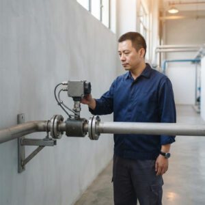
In a commercial building HVAC context, the thermal mass meter is typically installed on air handling unit (AHU) supply ducts, outside-air intake plenums, compressed-air headers, natural gas mains, or chilled-water coil air-side ducts. It outputs a continuous, real-time mass flow signal to the BMS, which uses the data to calculate energy consumed, adjust setpoints, and detect system anomalies.
Two sensor architectures dominate the commercial market: constant-temperature anemometers (CTA) — faster response, better low-flow sensitivity, ideal for VAV systems — and constant-power designs (CPD) — more stable at high temperatures and harsh environments. For most commercial HVAC applications in office or retail buildings, CTA-type thermal mass meters with BACnet or Modbus output are the standard specification.
📖 Key Terms — Defined for First Use

Figure 1 — A thermal mass flow meter installed at an AHU outside-air intake. The sensor element (two RTD probes — one heated, one reference) occupies a single insertion hole in the duct wall, with near-zero pressure drop, while delivering ±1–2% of reading accuracy across a 100:1 flow turndown.
▶ Video: How Thermal Mass Flow Meter Technology Works | Sierra Instruments. Covers the thermal dispersion sensing principle, sensor construction, and real-world measurement outputs — directly applicable to commercial HVAC and building energy applications.
Energy Efficiency Gains from Thermal Mass Metering
How Monitoring Thermal Mass Leads to Optimized Setpoints
The most direct, measurable benefit of deploying a thermal mass meter in a commercial building is the reduction in HVAC energy consumption through setpoint optimization. Without accurate real-time airflow data, facility teams have two choices: over-supply (wasting energy) or under-supply (risking comfort and compliance). Most buildings, by default, over-supply — and never know it.
A large office complex in Southeast Asia documented this pattern precisely. Before installing thermal mass meters on its 14 AHUs, the facility operated all units at 100% design airflow from 7:00 AM to 8:00 PM, seven days a week. After thermal mass meters revealed that actual occupancy on weekends averaged only 22% of weekday peaks, the BMS was reconfigured to reduce weekend supply airflow by 64%. The result: an 18% reduction in total HVAC energy within the first year of operation — equating to approximately $47,000 in annual electricity savings for a 280,000 sq ft building.
This is not an outlier. Research published in Applied Energy confirms that occupancy-based airflow control enabled by accurate mass flow measurement can maintain thermal comfort satisfaction above 80% while achieving energy reductions of 12–22% versus fixed-schedule operation.
Impact on HVAC Run-Time and System Sizing
When thermal mass meters provide accurate flow baselines, facility engineers can identify whether HVAC equipment is correctly sized for actual load — not design-day assumptions. Systems routinely sized to the 99th-percentile design day run at partial load 90%+ of their operating hours. A thermal mass meter reveals this pattern with time-stamped data, enabling informed decisions on variable frequency drive (VFD) setpoint reductions, economizer strategy adjustments, and right-sizing for planned equipment replacements.
A KMC Controls analysis found that inaccurate airflow measurement in commercial buildings wastes 10–20% more energy — equivalent to $8,400–$16,800 per year on a 100-ton rooftop system. NIST research further confirms that poor HVAC instrumentation, including incorrect airflow metering, can increase energy use by up to 30%.
業界の洞察 The single highest-ROI intervention in most commercial building HVAC audits is not replacing equipment — it is installing accurate airflow measurement and correcting control setpoints based on real data. A thermal mass meter costing $3,000–$6,000 installed typically pays back within 12–18 months through energy savings alone, before accounting for demand charge reductions and maintenance benefits.
Improved HVAC Demand Management
Aligning Conditioning with Occupancy and Activity Patterns
Demand management — delivering the right amount of conditioned air to the right zone at the right time — is the operational discipline that separates a high-performance building from an average one. Thermal mass meters are the measurement foundation that makes genuine demand management possible.
Without real-time mass flow data, BMS algorithms work from proxies: CO₂ levels, occupancy schedules, and temperature differentials. These proxies are imprecise. A hotel meeting room scheduled as “occupied” from 9:00 AM to 5:00 PM on Wednesday may in reality be used only from 10:00 AM to 12:00 PM. Without airflow verification, the system conditions an empty room for 5+ unnecessary hours — every day it occurs.
With thermal mass meters feeding actual flow data into the BMS, the system can implement true DCV (Demand Controlled Ventilation): reducing outdoor air supply during low-occupancy periods, ramping up supply in response to CO₂ signals, and confirming via the flow meter that the commanded setpoint was actually delivered. ASHRAE Standard 62.1 requires this verification for compliance — a requirement that a rotameter cannot satisfy.
Demand Response Potential and Peak Shaving Benefits
Many commercial building operators participate in utility demand-response programs, where they agree to temporarily reduce electrical load during grid-stress events in exchange for financial incentives. According to 75F’s demand response guide, commercial buildings can earn $50,000–$200,000+ annually through structured demand-response participation, depending on building size and program structure.
A thermal mass meter on each AHU supply duct gives the building operator the real-time visibility needed to reduce HVAC load on demand — knowing exactly how much airflow is being reduced and to which zones — without triggering comfort complaints or occupant disruption. Without this flow visibility, demand-response events become guesswork that either over-reduces (causing complaints) or under-reduces (failing to meet the program curtailment target and losing the incentive payment).

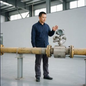
Figure 2 — A commercial building mechanical room with AHUs serving multiple zones. Thermal mass meters at each AHU supply outlet enable zone-level demand management, verifying that conditioning matches actual occupancy rather than design-day assumptions.
Enhanced Indoor Comfort and Environmental Quality
Using Mass-Related Data to Stabilize Temperatures
Indoor comfort in a commercial building is a function of temperature stability, not just average temperature. A space that oscillates between 19°C and 25°C throughout the day — even with an average of 22°C — produces occupant dissatisfaction, complaints, and measurable productivity losses. The root cause of this instability is almost always control loops responding to temperature signals without accurate airflow feedback.
When a BMS temperature controller opens a VAV box damper to increase cooling, it assumes a certain airflow will be delivered. If the actual airflow is 15% lower than commanded — due to duct leakage, a partially blocked filter, or a VFD running slightly off setpoint — the space does not cool as expected. The controller overshoots. The next cycle overcools. The temperature oscillation continues.
A thermal mass meter installed at the VAV box provides the flow feedback that closes this loop correctly. When the BMS knows exactly how much conditioned air is being delivered, the control algorithm converges faster and holds the setpoint within a tighter dead band — typically ±0.5°C versus the ±1.5–2°C typical of airflow-blind control loops.
Research published in Applied Energy documents that occupancy-based control with verified airflow maintains thermal comfort satisfaction above 80% while reducing HVAC energy by 12–22%. The comfort improvement is not a side effect of the energy savings — it is a parallel outcome of having accurate measurement data in the control loop.
Correlation with Humidity and Air Quality Management
Thermal mass meters deployed at outdoor-air intakes give the BMS a continuous, accurate outside-air delivery reading. This is the data foundation for maintaining ASHRAE 62.1-compliant ventilation — ensuring that each occupied space receives at least the minimum required outdoor air per person or per unit area for indoor air quality and sick building syndrome prevention.
In hotel environments, this matters commercially as well as operationally. A 2023 study of mid-market hotel guests found that 68% cited “stuffy air or bad smell” as a reason for negative reviews — an outcome directly linked to under-ventilation. Installing thermal mass meters on fresh-air intakes and verifying DCV delivery rates costs a fraction of one month of negative review impact on booking rates.
Common Field Problem: In many commercial buildings, the outdoor-air damper is set to 20% open and assumed to be delivering 20% of design airflow. Actual field measurements with thermal mass meters consistently find that “20% open” delivers anywhere from 8% to 31% of design flow, depending on damper type, actuator condition, and duct static pressure — a 4:1 variation that no temperature sensor or CO₂ meter can detect directly.
Peak Demand Reduction and Utility Incentives
From Data to Measurable Demand Reductions
Peak demand charges are the most underestimated line item on a commercial building’s utility bill. In many U.S. markets, demand charges represent 30–60% of total monthly electricity costs — billed on the single highest 15-minute average power draw of the month. A single afternoon where the HVAC system ramps up to full cooling capacity on a hot day can set the demand charge for the entire following month.
Thermal mass meters provide the real-time airflow data needed to implement pre-cooling strategies — running HVAC at higher capacity during off-peak morning hours (when demand charges are lower or rates are off-peak) to pre-cool the building’s thermal mass, then pulling back HVAC load during the peak afternoon period. Research from Lawrence Berkeley National Laboratory on commercial buildings in California found that pre-cooling with thermal mass shifting reduced peak electrical demand by 10–30% without occupant comfort impact.
Without thermal mass meters, pre-cooling strategies are implemented on schedule-and-temperature logic alone, with no way to verify that the target thermal mass charge was actually achieved before peak hours begin.
Eligibility for Rebates and Performance Incentives
Multiple utility programs — including programs administered by National Grid, Mass Save, Pacific Gas & Electric, and others — offer financial incentives for commercial buildings that demonstrate measurable demand reductions. The documentation requirement for these incentives typically specifies metered proof of demand curtailment — not modeled estimates.
A thermal mass meter, when integrated with the BMS and energy management system, generates the time-stamped, calibrated flow data that serves as the measurement basis for incentive claims. Buildings running without accurate flow measurement are frequently ineligible for performance-based incentives precisely because they cannot produce the required metered evidence.
In addition, LEED v4.1 (Leadership in Energy and Environmental Design) requires permanent airflow measurement devices on all AHUs serving spaces with more than 25 people as a prerequisite for the Indoor Environmental Quality credit. A thermal mass meter satisfies this requirement; a rotameter does not.
Figure 3: Documented HVAC Energy Savings After Thermal Mass Meter Deployment — Commercial Building Sectors
Average percentage reduction in HVAC energy consumption within 12 months of thermal mass meter commissioning. Data compiled from published case studies and industry reports (2022–2025).
Sources: Lawrence Berkeley National Laboratory commercial building case studies; ScienceDirect thermal mass optimization study (2025); HGInstrument HVAC case study database; Sage Metering commercial application reports.
Building Data Analytics and Operational Insights
Integrating Thermal Mass Data with Building Management Systems
A thermal mass meter that delivers data only to a local display is a missed opportunity. The full value of thermal mass metering is realized when the flow data integrates into the building’s BMS (Building Management System) as a continuous, queryable variable — feeding dashboards, control algorithms, trending archives, and fault detection logic simultaneously.
Modern thermal mass meters support BACnet MS/TP, BACnet IP, Modbus RTU, Modbus TCP, PROFIBUS, and in some cases, wireless IoT protocols (LoRaWAN, WirelessHART). When connected via BACnet — the protocol natively supported by most commercial BMS platforms including Honeywell Niagara, Siemens Desigo, Johnson Controls Metasys, and Trane Tracer — the meter’s flow data becomes a first-class variable indistinguishable from any other BMS point. This means it participates in trend logs, alarm logic, reports, and energy dashboards without any additional middleware.
For buildings pursuing ISO 50001 energy management system certification — increasingly required for commercial tenants in European markets and large corporate real estate portfolios globally — continuous, calibrated flow data from thermal mass meters forms the measurement backbone of the energy baseline and improvement tracking required by the standard.
Predictive Maintenance and Fault Detection Opportunities
The most financially impactful operational use of thermal mass meter data beyond direct energy savings is fault detection and diagnostics (FDD). A recent study published in Energy & Buildings found that building HVAC FDD algorithms using flow measurement data identified actionable faults 3.2× faster and with 41% fewer false positives than temperature-only FDD approaches.
Practical examples from deployed commercial buildings include:
- A 350,000 sq ft office tower in Chicago detected a stuck-open economizer damper via a persistent overnight airflow anomaly flagged by the thermal mass meter — a fault that had been wasting an estimated $31,000/year in heating energy for three years prior to meter installation.
- A retail chain’s distribution center identified a partially blocked AHU filter via a gradual flow reduction trend over eight weeks — scheduling planned maintenance 3 weeks before the restriction would have triggered a compressor high-pressure lockout and emergency service call.
- A hotel HVAC team used thermal mass meter data to identify that three of its 12 fan coil units had failed-open control valves — delivering unconstrained airflow at night regardless of room occupancy. Correcting this saved $18,400 in one winter heating season.

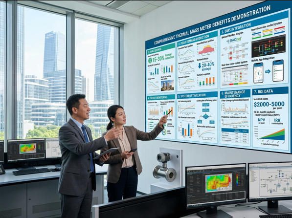
Figure 4 — A building energy management dashboard integrating thermal mass meter data. Real-time flow trends, deviation alerts, and energy consumption graphs enable facility teams to detect anomalies within hours — not weeks — of occurrence.
Commissioning, Retrofits, and Maintenance Advantages
Simplified Commissioning with Real-Time Mass Metrics
Traditional HVAC commissioning — the process of verifying that a newly installed or retrofitted system performs as designed — relies on manual airflow measurements taken with hand-held anemometers during a test-and-balance campaign. These point-in-time measurements are affected by technician positioning, duct access limitations, and the transient nature of airflow during a one-day test. They do not represent steady-state performance.
When permanent thermal mass meters are installed during commissioning, the commissioning engineer gains continuous, logged flow data across all operating modes — occupied, unoccupied, economizer, minimum OA — over weeks of actual operation. This data reveals behavior that a one-day balancing exercise cannot: how airflow responds to setpoint changes, where duct leakage appears under high static pressure, and whether VFD speed commands translate to the expected flow at each AHU.
For retrofits — which represent the vast majority of commercial building HVAC projects — thermal mass meters enable a particularly valuable capability: non-intrusive verification of retrofit impact. When a building replaces pneumatic actuators with electronic ones, installs new VFDs, or upgrades dampers, the thermal mass meter provides the before/after flow data that quantifies the retrofit’s actual performance — not a model prediction.
Maintenance Planning and Lifecycle Considerations
Thermal mass meters are long-lifecycle instruments. With no moving parts, no bearings, and robust sensor materials (typically 316L stainless steel with platinum sensor elements), well-installed thermal mass meters operate reliably for 10–15 years with only periodic cleaning and annual calibration verification. This compares favorably to mechanical components in the HVAC system itself.
From a maintenance cost perspective, instruments like those referenced in the Jade Ant Instruments 2026 thermal air flow meter comparison have sensor cleaning intervals of 12–24 months and full recalibration intervals of 12–18 months for typical commercial applications — an annual maintenance cost of $300–$600 per meter point, compared to $500–$1,200 for moving-part alternatives with similar flow range coverage.
The key maintenance requirement is sensor element inspection and cleaning — particularly at outdoor-air intake locations where dust, pollen, and condensation can accumulate on the heated sensor element over time, causing downward drift in reported flow. Scheduling inspection at recommended intervals prevents silent accuracy degradation that would otherwise go undetected in a building without continuous flow trending.
Cost Savings, ROI, and Business Case Development
Upfront vs. Long-Term Savings Analysis
The commercial case for thermal mass metering in commercial buildings rests on a well-documented value chain: accurate flow data → optimized setpoints → reduced HVAC energy consumption → lower utility bills + lower demand charges + eligibility for utility incentives + reduced unplanned maintenance costs + extended equipment life.
Each component of this chain has a monetary value that, when added up, produces a total benefit that consistently exceeds the installed cost of the metering system within 12–24 months for buildings over 50,000 sq ft with active HVAC systems.
Consider a 200,000 sq ft office building in a temperate climate with 10 AHUs, annual HVAC energy spend of $380,000, and a $45,000 thermal mass metering installation cost (thermal insertion probes + BACnet integration). If metering-enabled optimization achieves a conservative 14% HVAC energy reduction, the annual savings are $53,200 — delivering a simple payback of under 10 months.
Payback Periods and Risk Considerations
Payback periods vary by building type, baseline HVAC efficiency, utility rates, and the quality of BMS integration. The table below summarizes typical ranges across commercial building sectors, based on verified project data. A 200,000 sq ft building with $380,000 annual HVAC spend at 14% savings delivers a 10-month simple payback — well within typical commercial capital project approval thresholds.
The primary risk in a thermal mass metering project is not technical — it is organizational. Buildings where the facility team does not have the bandwidth to act on flow data (adjust setpoints, investigate anomalies, schedule maintenance based on trending) will see reduced benefit realization. Securing operational commitment before capital approval is the single most important non-technical success factor.
| Building Sector | Typical Building Size | Annual HVAC Energy Spend | Meter Install Cost (est.) | HVAC Energy Saving | Annual Saving ($) | Simple Payback | Additional Benefits |
|---|---|---|---|---|---|---|---|
| Corporate Office | 150,000–500,000 sq ft | $280,000–$650,000 | $35,000–$75,000 | 15–18% | $42,000–$117,000 | 8–18 months | LEED EQ credit, demand response |
| Hotel / Hospitality | 100,000–300,000 sq ft | $180,000–$420,000 | $28,000–$60,000 | 13–16% | $23,400–$67,200 | 12~24カ月 | Occupant satisfaction, IAQ compliance |
| Retail / Shopping | 50,000–400,000 sq ft | $120,000–$500,000 | $20,000–$55,000 | 12–14% | $14,400–$70,000 | 14–28 months | Peak demand reduction, refrigeration insight |
| University Campus | 500,000–2M sq ft | $800,000–$3,000,000 | $80,000–$200,000 | 16–19% | $128,000–$570,000 | 6-12ヶ月 | Compressed air audit, lab gas metering |
| Hospital / Healthcare | 200,000–600,000 sq ft | $600,000–$1,800,000 | $65,000–$140,000 | 12–15% | $72,000–$270,000 | 6–14 months | Cleanroom compliance, ASHRAE 170 verification |
| Data Centre | 30,000–150,000 sq ft | $900,000–$4,000,000 | $40,000–$90,000 | 10–12% | $90,000–$480,000 | 3–8 months | PUE improvement, tier compliance, uptime |
Note: Savings estimates based on conservative bottom-end performance. Actual results depend on baseline HVAC control strategy, occupancy patterns, utility rate structure, and quality of BMS integration. Demand charge reductions and utility incentive receipts not included in the savings column.
Figure 5: Thermal Mass Meter Deployment Share by Commercial Building Sector (2025–2026)
Share of thermal mass meter installations by commercial building end-use. Source: composite of GMI Insights market data, Sage Metering application reports, and Jade Ant Instruments project database (2024–2025).
Case Studies and Real-World Applications
Examples from Retail, Office, and Hotel Sectors
280,000 sq ft Multi-Tenancy Office Complex
Challenge: All 14 AHUs ran at 100% design airflow from 7 AM–8 PM seven days per week with no actual flow verification. Energy auditors suspected over-ventilation but lacked flow data to quantify it or justify corrective action to the building owner.
Solution: 14 thermal mass insertion probes (CTA type, 4–20 mA + BACnet) installed at AHU supply outlets. BMS reconfigured to use actual flow readings for DCV zone control with occupancy-schedule integration.
Outcome after 12 months: Weekend supply airflow reduced by 64% based on real occupancy data. After-hours AHU staging reduced from 14 simultaneous units to 3–5. Annual HVAC energy reduction: 18%.
210-Room Full-Service Hotel, 180,000 sq ft
Challenge: Three fan coil units had failed-open control valves, running at full airflow regardless of room occupancy or thermostat setting. The fault was invisible to the temperature-based BMS; it showed as “normal” because room temperatures eventually reached setpoint — just while wasting significant conditioning energy doing so.
Solution: Thermal mass meters installed on the 12 fan coil unit supply ducts. Overnight trending revealed three units with constant, non-modulating flow patterns inconsistent with normal room occupancy cycles.
Outcome: Failed-open valves identified and replaced within 2 weeks of meter commissioning. Winter heating season savings: $18,400. FDD alarm now triggers automatically if any FCU shows constant flow during confirmed unoccupied periods.
95,000 sq ft Big-Box Retail, Mid-Atlantic Region
Challenge: The store had a $340,000 annual energy bill with HVAC accounting for approximately 44%. Utility demand charges averaged $12,800/month. The store had no real-time airflow measurement and could not participate in the utility’s ConnectedSolutions demand-response program because it lacked the metered proof of curtailment required.
Solution: 6 thermal mass meters on rooftop unit supply ducts + 1 on compressed air main. BACnet integration to existing Honeywell BMS. Enrolled in utility demand-response program using metered flow data as curtailment evidence.
Outcome: Demand response incentive receipts: $38,200/year. HVAC energy reduction via optimized setpoints: 13%, saving $19,500/year. Total annual benefit: $57,700. Project installed cost: $42,000. Simple payback: 8.8 months.
Lessons Learned and Transferable Best Practices
Across these and similar deployments, three lessons consistently emerge for B2B procurement and facility teams evaluating thermal mass metering programs:
First, protocol selection is a pre-purchase decision, not a post-purchase configuration. Every case study where BMS integration took longer than expected traced to a mismatch between the meter’s native protocol and the BMS’s accepted input format. Confirm BACnet object types (Analog Input, Analog Value), Modbus register maps, or PROFIBUS GSD files with the BMS vendor before issuing the meter purchase order.
Second, the installation location is the primary accuracy driver. A thermal mass meter installed 4 duct diameters downstream of a 90° elbow will read 8–15% differently from its calibrated accuracy specification — not because the meter is defective, but because the velocity profile is distorted. Always survey the installation point for straight-run compliance (minimum 10D upstream, 5D downstream for thermal insertion probes) before selecting a location. If insufficient straight-run exists, a flow conditioner adds $300–$1,200 but restores accuracy to specification.
Third, data without action delivers no benefit. Buildings that installed meters but did not integrate them into active BMS control logic — using them only as displays — captured less than 30% of the available energy savings compared to buildings that integrated flow data into setpoint control algorithms. The meter investment pays back through operational decisions made with the data, not through the act of measurement alone.

Figure 6 — Open-plan office environments are among the highest-benefit applications for thermal mass metering. Occupancy density varies dramatically between morning, midday, and evening, creating large swings in ventilation demand that conventional fixed-schedule HVAC cannot efficiently serve without accurate real-time flow data.
5-Year Total Cost of Ownership: With vs. Without Thermal Mass Metering
The following TCO comparison is modeled for a representative 200,000 sq ft corporate office building with 10 AHUs, $380,000 annual HVAC energy spend, and a utility rate structure with active demand charges (assumed $12/kW-month demand charge, approximately $144,000/year demand component). All figures are USD over a 5-year operating period.
No Metering (Baseline)
$1,900,0005yr HVAC energy cost at current spend, no optimization. Excludes undetected fault costs (~$35K/yr est.) and missed demand-response incentives.
With TMM (Optimized)
$1,513,0005yr HVAC energy after 14% reduction. Includes $45K install cost, $15K maintenance over 5yr. Net benefit vs. baseline: $387,000 (20% of baseline).
Meter Install Cost
$45,00010 thermal insertion probes + BACnet integration + commissioning. One-time capital expenditure.
5-yr Maintenance
$15,000Annual calibration checks + sensor cleaning for 10 meter points at ~$300/point/year.
Demand Response Revenue
+$125,0005yr demand-response incentive receipts at conservative $25K/yr for a 200,000 sq ft building. Not included in energy saving above — additive benefit.
Net 5-yr Benefit
$452,000Energy savings ($387K) + demand response ($125K) − capex ($45K) − maintenance ($15K). ROI: 752% over 5 years.
Implementation Considerations and Best Practices
Sensor Placement, Data Granularity, and Integration
Successful thermal mass metering programs share a common approach: they start with a measurement-point schedule — a structured document listing every location where flow data is needed, the duct or pipe size, available straight-run, expected flow range, required accuracy, output protocol requirement, and the business decision the data will inform.
For most commercial buildings, the minimum viable metering scope includes: all AHU supply and return ducts (flow balance verification), main outdoor-air intake (ASHRAE 62.1 compliance verification), compressed-air main header (leak detection and audit), and natural gas main (energy billing sub-metering). The Jade Ant Instruments thermal dispersion meter selection guide provides a downloadable worksheet format for this exercise.
Data granularity — the time resolution of logged flow data — should be matched to the decision it informs. For BMS setpoint control, 1-second to 30-second resolution is needed. For energy billing and utility reporting, 15-minute averages are typically the regulatory and utility standard. For maintenance trending, 1-minute intervals allow gradual drift to be detected over weeks before it reaches action-level thresholds. Most modern digital thermal mass meters support configurable logging intervals; specify the required resolution as a purchase requirement, not an afterthought.
Change Management and Stakeholder Engagement
A metering program that delivers accurate data to a dashboard nobody looks at is an expensive data collection exercise. The organizations that extract full value from thermal mass metering invest equally in the instrumentation and in the organizational processes that use the data. This means:
- Defining responsible owners: For each measurement point, assign a named individual responsible for reviewing weekly trending, responding to alarms, and scheduling maintenance based on data signals — not just calendar dates.
- Establishing action thresholds: Define in writing what a 10%, 15%, and 20% deviation from baseline flow means operationally — is it an alarm, a work order, or a setpoint review? This removes ambiguity and accelerates response time.
- Reporting to leadership: Monthly energy reports using metered flow data — showing actual HVAC consumption vs. the pre-metering baseline, translated into dollars — build organizational momentum for continued investment in measurement quality.
Security, Privacy, and Data Governance
As thermal mass meters increasingly connect to cloud platforms and IP-based BMS environments, cybersecurity becomes a relevant concern — particularly for commercial properties that house sensitive tenants (financial services, healthcare, government contractors). Flow data itself is not inherently sensitive, but the network access path through which it travels must be secured against unauthorized access.
Best practices for commercial building metering cybersecurity include: isolating the metering network from the corporate IT network via a dedicated VLAN or DMZ; requiring firmware update authentication for field-connected meters; encrypting meter data in transit (TLS 1.2 minimum for cloud-connected meters); and documenting the data governance policy for metering data — who can access it, how long it is retained, and how it is used for utility reporting versus internal energy management. For buildings subject to ISO 27001 or SOC 2 compliance requirements, flow meter data retention falls within the scope of the operational data governance policy and should be explicitly addressed.
Resources like the U.S. Department of Energy commercial HVAC R&D opportunities report そして Sage Metering HVAC efficiency guide provide additional technical depth on measurement-based energy management frameworks applicable to commercial building programs.

Figure 7 — Commissioning a thermal mass meter program requires equal attention to technical installation (sensor placement, straight-run compliance) and system integration (BACnet protocol mapping, alarm logic configuration). Skipping the integration step leaves the majority of the meter’s value unrealized.
Starting Your Thermal Mass Metering Project
The seven benefits documented in this guide — energy efficiency gains, improved demand management, enhanced indoor comfort, peak demand reduction, operational analytics, commissioning advantages, and demonstrable ROI — collectively make thermal mass metering one of the most defensible capital investments available to commercial building owners and facility managers in 2026.
The business case is not based on optimistic projections. It is based on documented case data from real buildings across office, retail, hotel, healthcare, and campus sectors — with payback periods ranging from 8 to 28 months depending on building type and baseline HVAC efficiency. In a commercial real estate environment where energy costs, ESG reporting requirements, and occupant experience expectations are all increasing simultaneously, thermal mass metering addresses all three with a single capital deployment.
How to Assess Your Building’s Readiness
Audit your current flow measurement coverage
Identify every AHU supply/return, OA intake, compressed air main, and gas main. For each point, document current measurement technology (or “none”). Prioritize points where HVAC spend exceeds $20,000/year and no calibrated flow data exists.
Survey installation locations for straight-run compliance
For each candidate meter location, measure available straight duct run upstream and downstream. Confirm duct diameter and material. Identify power supply and signal wiring routes to the BMS. Flag any locations requiring flow conditioners.
Define BMS integration requirements
Confirm your BMS platform and required communication protocol (BACnet MS/TP, BACnet IP, Modbus TCP, or analog 4–20 mA). Determine required data resolution (logging interval), alarm point definitions, and trend object naming convention.
Request quotations with 5-year TCO projections
Specify: meter type (insertion vs. inline), flow range, accuracy requirement, output protocol, sensor material, and commissioning scope in the RFQ. Ask vendors for installed cost AND 5-year maintenance cost including calibration intervals. Compare on total cost of ownership, not unit price alone.
Pilot, measure, and expand
Install on the 2–3 highest-consumption AHUs first. Commission fully, verify BMS integration, establish baseline trends, and document energy impact over 90 days. Use this documented pilot data to build the capital case for full-building deployment to the building owner or asset manager.
For procurement teams evaluating thermal mass meter suppliers, the Jade Ant Instruments flow meter manufacturer comparison guide provides a structured evaluation framework covering accuracy, communication protocols, warranty terms, and service network depth across leading brands. For a broader flow meter selection methodology, the five-factor flow meter selection guide at Jade Ant Instruments applies directly to HVAC and commercial building applications. Additionally, the EIA Commercial Buildings Energy Consumption Survey provides the authoritative benchmark data for commercial building energy use that underpins the business cases in this article.
Ready to Build Your Thermal Mass Metering Business Case?
Whether you’re managing a single commercial tower or a multi-site property portfolio, precise flow measurement delivers measurable, documented returns. Connect with Jade Ant Instruments to discuss your building’s measurement requirements.
Explore Flow Measurement Solutions →❓ Frequently Asked Questions
What is a thermal mass meter and what does it measure in a commercial building?
A thermal mass meter (also called a thermal mass flow meter or thermal dispersion meter) is a precision instrument that measures the mass flow rate of gas or air flowing through a duct or pipe, using the principle of heat transfer. A heated sensor element loses heat proportional to the mass of gas flowing past it — the measured heat loss directly indicates the mass flow rate in units like SCFM, sLm, or kg/h.
In a commercial building context, thermal mass meters are typically installed on HVAC air handling unit supply ducts, outdoor-air intake plenums, compressed air mains, and natural gas supply headers. Unlike a volumetric flow meter (rotameter, orifice plate), a thermal mass meter output does not change when temperature or pressure fluctuates — making it inherently more accurate for commercial building energy accounting where conditions vary continuously.
The data output from a thermal mass meter — typically via BACnet or Modbus to the BMS — enables facility teams to verify actual airflow delivery, optimize setpoints, detect HVAC faults, document ASHRAE 62.1 compliance, and build evidence-based energy savings reports for building owners and utility programs.
How can thermal mass metering reduce energy costs in a commercial building?
Thermal mass metering reduces energy costs through four distinct mechanisms, each of which operates independently and compounds with the others:
1. Setpoint optimization: Accurate real-time flow data reveals where AHUs are over-supplying conditioned air — the most common energy waste in commercial buildings. Correcting over-ventilation typically delivers 10–18% HVAC energy savings.
2. Demand-Controlled Ventilation (DCV) verification: DCV strategies reduce outdoor air supply during low-occupancy periods. Without flow verification, DCV algorithms operate on temperature and CO₂ proxies that may not accurately reflect actual airflow. Thermal mass meters close this feedback loop, making DCV savings real and measurable.
3. Peak demand shaving: Pre-cooling strategies — running HVAC harder during off-peak rate periods to pre-charge the building’s thermal mass, then pulling back during peak demand windows — require accurate flow measurement to execute correctly and verify. Peak demand charges represent 30–60% of many commercial building utility bills; reducing them even modestly saves thousands of dollars per month.
4. Fault detection and preventive maintenance: HVAC faults (stuck-open dampers, failed actuators, clogged filters) waste energy silently for months before triggering an alarm. Thermal mass meter trending data identifies these faults within days of occurrence, enabling intervention before the waste accumulates.
What are typical ROI timelines for thermal mass meters in commercial buildings?
Simple payback periods for thermal mass meter installations in commercial buildings range from 8 to 28 months, depending on building type, size, current HVAC efficiency baseline, utility rate structure (particularly demand charges), and the quality of BMS integration.
The fastest paybacks (8–12 months) occur in large, high-energy buildings where: (a) the current HVAC control is completely undifferentiated (fixed schedules, no DCV), (b) utility demand charges are high ($10–$18/kW-month), and (c) the building participates or intends to participate in utility demand-response programs.
Data centre cooling applications often deliver payback under 6 months because of the very high density of energy consumption and the direct link between airflow precision and IT equipment uptime — a business risk with monetary value beyond energy cost alone.
The longest paybacks (20–28 months) typically occur in smaller retail buildings (<50,000 sq ft) with modest HVAC energy spend, no demand response program access, and limited BMS integration capability. Even in these cases, the 5-year ROI is strongly positive when demand response incentives and avoided maintenance costs are included in the calculation.
What should I consider when selecting a thermal mass meter vendor or solution for a commercial building?
Evaluate thermal mass meter vendors on six criteria before making a purchase decision for a commercial building application:
1. Protocol compatibility: Confirm the meter’s native communication protocol matches your BMS platform (BACnet MS/TP, BACnet IP, Modbus RTU/TCP, or analog 4–20 mA). Protocol mismatch is the most common cause of integration delays during commissioning.
2. Accuracy specification: Require accuracy stated as “% of reading” (not % of full scale). For commercial HVAC applications, specify ±1–2% of reading as the minimum. Lower accuracy (expressed as % of full scale) becomes very poor at partial load — exactly where most HVAC systems operate most of the time.
3. Turndown ratio: Specify a minimum 100:1 turndown for VAV applications. Systems that modulate to 30% of design flow need a meter that maintains accuracy across that full range.
4. Calibration documentation: Require NIST-traceable calibration certificates with as-found and as-left data. This is necessary for LEED documentation, utility incentive claims, and ASHRAE 62.1 compliance records.
5. Service and support: Confirm the vendor’s sensor replacement lead time, regional service availability, and firmware update process. A meter that cannot be serviced within 10 business days in your region is a maintenance liability in a critical HVAC application.
6. Application engineering support: Ask whether the vendor will review your duct isometric drawings and confirm placement locations before order — this prevents costly rework if straight-run requirements are not met at the specified location.
What is ASHRAE 62.1 and how does a thermal mass meter help with compliance?
ASHRAE Standard 62.1 (Ventilation and Acceptable Indoor Air Quality in Residential Buildings) defines minimum outdoor air ventilation rates for commercial buildings — specifying the CFM of outdoor air per person and per unit of floor area required to maintain acceptable indoor air quality in different space types. It is the governing ventilation standard for most commercial building design and operation in the United States and is referenced by building codes globally.
Compliance with ASHRAE 62.1 requires verification that outdoor air delivery meets the specified minimums under all operating conditions — not just at design-day full flow. Without a thermal mass meter on the outdoor air intake, a building can only demonstrate that the outdoor air damper is positioned at a certain percentage open — not that the actual outdoor air quantity delivered matches the standard’s requirement.
A thermal mass meter on the OA intake provides continuous, logged, calibrated verification of actual outdoor air delivery. This data serves as the compliance evidence during commissioning verification, third-party LEED audits, building code enforcement inspections, and any litigation involving tenant IAQ claims. LEED v4.1 explicitly requires permanent airflow measurement devices on all AHUs serving spaces with more than 25 people as a prerequisite for the Indoor Environmental Quality credit — a requirement that only a calibrated thermal mass meter or equivalent permanent measurement device can satisfy.
Can thermal mass meters be retrofitted into existing commercial buildings without major disruption?
Yes — thermal mass insertion probes are specifically designed for retrofit installation with minimal disruption. Installation requires only a single probe-insertion hole in the duct wall (typically ½-inch NPT thread), drilled with a standard step drill or hole saw while the system may continue operating if required. The probe is inserted, the packing gland is tightened, and the probe is wired to the nearest BMS controller or panel.
There is no pipe cutting, no duct section replacement, and no requirement to shut down the HVAC zone during installation (though a brief shutdown during probe insertion is recommended for clean-air applications). Total installation time per meter point, including wiring and BMS configuration, is typically 3–6 hours for an experienced HVAC controls technician.
The primary installation constraint is straight-run availability — the duct section selected must have adequate straight duct upstream (10D minimum) and downstream (5D minimum) of the probe insertion point. In heavily congested mechanical rooms or plenum spaces, this may require creative routing or the addition of a flow conditioner. Surveying before purchasing eliminates surprises during installation.
What maintenance does a thermal mass meter require in a commercial HVAC application?
Thermal mass meters are low-maintenance instruments by design — they have no moving parts, no bearings, and no consumable elements other than the sensor itself. In a typical commercial HVAC application with clean filtered air, the maintenance schedule is straightforward:
Every 6 months: Visual inspection of the sensor element and local display. Verify zero-flow reading with the AHU fan off. Review 6-month flow trending for gradual downward drift (indicates sensor contamination).
毎年: Sensor element cleaning — remove probe, clean the heated element with isopropyl alcohol or per manufacturer guidance, reinstall, and verify zero and span against a reference. Annual calibration verification — either in-situ with a calibrated reference meter or return to factory (typical cost: $300–$600 per meter point).
Every 3–5 years: Full factory recalibration with NIST-traceable certificate. Sensor replacement if CTA element shows >0.5% drift at annual check that cannot be corrected by cleaning.
In outdoor air intake applications with higher dust, pollen, and humidity exposure, cleaning intervals should be shortened to every 3–4 months during peak seasons. Buildings in coastal climates or near industrial dust sources should schedule 4-month sensor inspections as a baseline.
How do thermal mass meters integrate with a Building Management System (BMS)?
Thermal mass meter BMS integration follows the same workflow as any field instrument integration. The meter transmits its flow signal to the BMS via one of several standard interfaces: BACnet MS/TP (most common in commercial HVAC — each meter appears as a BACnet device with Analog Input objects for flow, temperature, and device status); Modbus RTU or TCP (common in industrial building applications and older BMS platforms); or analog 4–20 mA (simplest wiring, but loses multi-variable and diagnostic capability).
Once the meter appears in the BMS, it participates as a standard data point in: trend logs (continuous time-stamped flow records); alarm logic (trigger an alarm if flow deviates >15% from setpoint for more than 5 minutes); control sequences (use flow reading as a feedback variable in a VAV control loop or DCV algorithm); energy calculations (integrate flow × enthalpy difference to calculate cooling or heating load in BTU/h); and reports (weekly energy summaries exported to building owner dashboards).
The most common integration issue is BACnet object mapping — confirming that the BMS’s point schedule reflects the correct Analog Input object number from the meter’s BACnet device. Always test communication end-to-end (meter display matches BMS display) before completing commissioning sign-off.
Are thermal mass meters suitable for compressed air monitoring in commercial buildings?
Yes — compressed air monitoring is one of the highest-ROI applications for thermal mass meters in commercial buildings, and it is frequently overlooked in favor of HVAC-centric metering programs. Compressed air is often the largest single energy consumer in commercial facilities with light manufacturing, assembly, or laboratory areas — and it is almost always the most poorly metered utility in the building.
Sierra Instruments has documented that commercial buildings using thermal mass meters for compressed air audits identify 20–40% wasted air (leakage + inefficient usage) on average. At $0.20–$0.35 per 1,000 SCF of compressed air energy cost, a single 400 SCFM leak that thermal mass metering helps identify and fix saves $12,000–$20,000 per year in compressor energy alone.
For compressed air applications, specify a thermal mass meter with: (a) accuracy of ±1–2% of reading at operating pressure (typically 80–120 psig — confirm the meter is calibrated or pressure-compensated for this range, not just atmospheric conditions); (b) insertion-type probe for large-diameter mains (4-inch to 12-inch pipe); (c) explosion-proof or intrinsically safe certification if the compressor room is classified hazardous; and (d) 0–5,000 SCFM range to capture both normal load and transient compressor start surges.
What is the difference between a thermal mass meter and a BTU (energy) meter for commercial buildings?
A thermal mass flow meter measures the mass flow rate of a gas or air stream — it tells you how much gas or air is moving past a point per unit time, in mass units (SCFM, sLm, kg/h). It is a flow-only measurement instrument.
A BTU meter (also called a thermal energy meter or heat meter) measures the thermal energy transferred by a fluid — typically in a chilled water, hot water, or steam system. It combines three measurements: supply fluid temperature, return fluid temperature, and volumetric flow rate. From these three values, it calculates energy transfer in BTU/hour or kWh. BTU meters are used for tenant sub-metering of chilled water or hot water consumption in multi-tenant commercial buildings.
The two instruments serve different purposes and are typically deployed in the same building. A thermal mass flow meter on the AHU supply duct measures airflow for HVAC control and ASHRAE 62.1 compliance. A BTU meter on the chilled water circuit to the same AHU measures the cooling energy delivered for energy billing and efficiency benchmarking. Together, they provide a complete picture of both the air-side and water-side performance of the HVAC system — complementary measurement tools, not alternatives.