Turbine Flow Meter Maintenance: A Practical MRO Guide
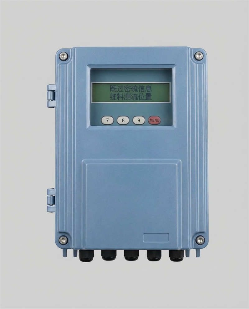
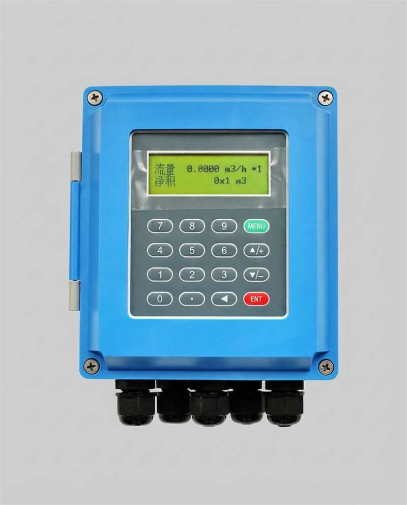
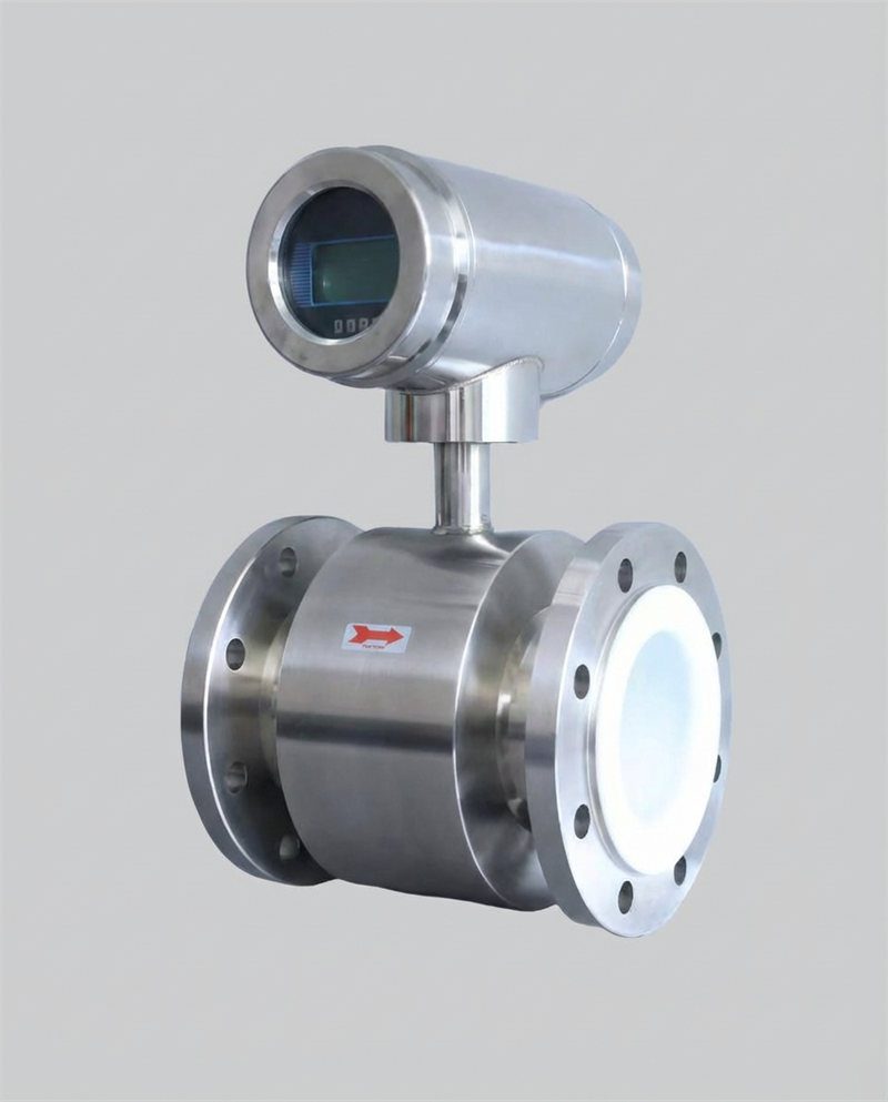
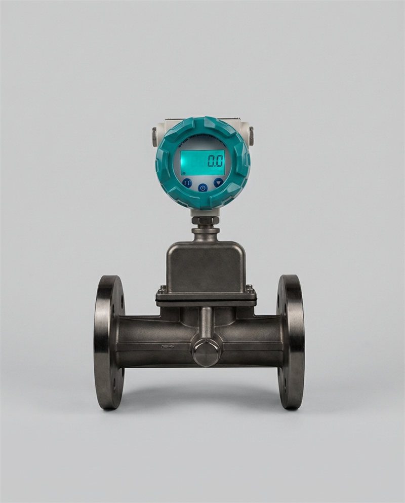
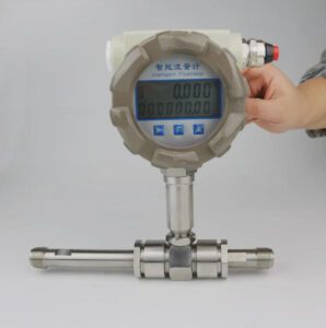
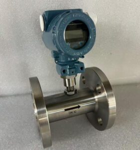
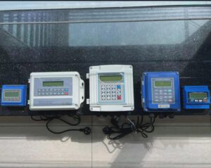
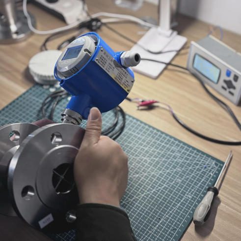
Image: Jade Ant Instruments product photo.
Quick answer: A turbine meter keeps its accuracy when you control three things: mechanical wear, dirt, and calibration. Check a baseline at commissioning, clean with the right method, and verify the K-factor on a schedule based on how costly an error is. In the 10-year example below, this approach cost about one-fifth of waiting for failures.
I. The critical role of turbine flow meters in high-stakes industrial processes
Turbine meters sit on fuel loading lines, solvent batching skids, treated-water mains, and cooling loops. They are popular because they are accurate and fast. Jade Ant Instruments’ turbine flow meter guide for distributors puts best-case accuracy near 0.25% of reading, with response times in milliseconds.
For an OEM building a skid, that accuracy decides whether a dosing batch stays in spec. For an EPC, it decides whether the handover test passes.
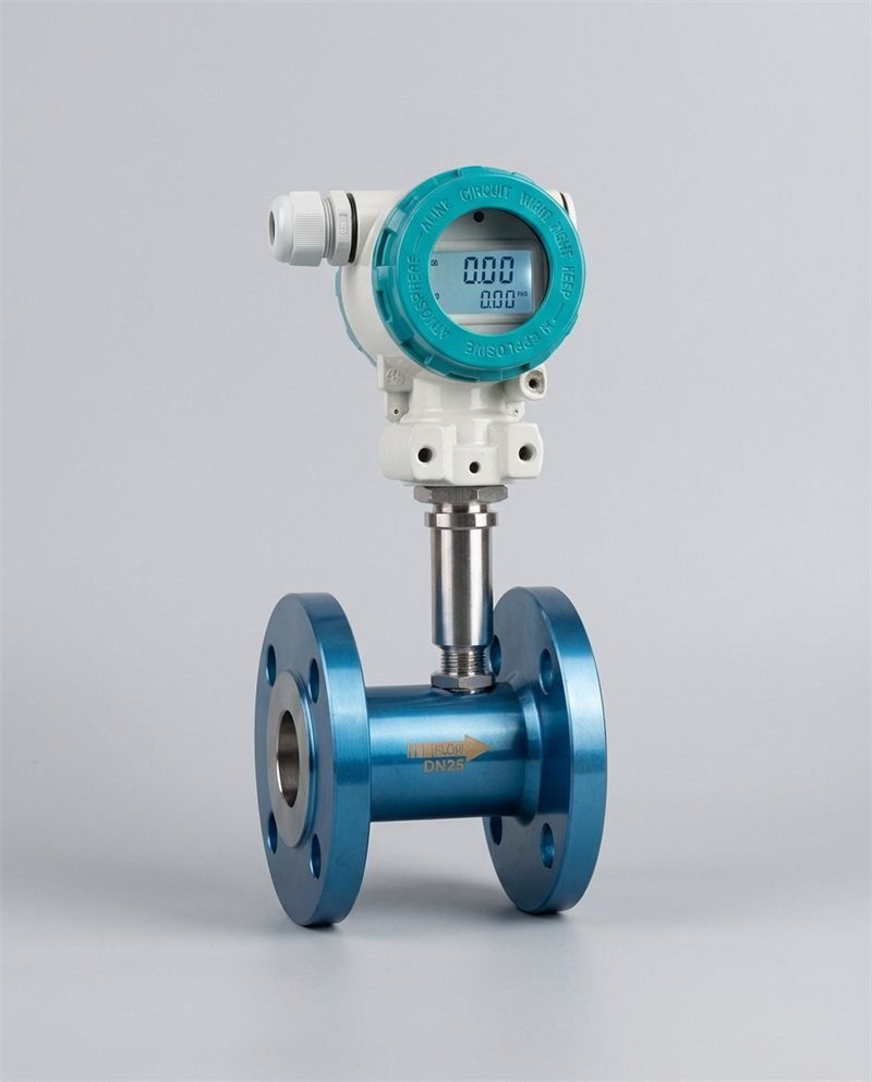
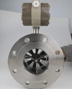
A turbine flow meter is a pipe section with a small free-spinning wheel (the rotor) inside. Moving fluid spins the rotor. A sensor outside the pipe counts each blade as it passes, and the count becomes flow.
The financial and operational impact of drift and unexpected failure
The rotor and bearings are the only moving parts. That is the strength of the design, and also the weak point.
Turbines Incorporated describes a fuel terminal that found a gap of about 1.5% between delivered and billed volume. The meters had run for 18 months, and bearing wear was the cause. Nobody had raised an alarm, because the meters kept reading.
Here is what that kind of gap costs. Assume a plant moves 100 m³ of solvent per day, and the product is worth 800 USD per m³:
That is about 438,000 USD a year from one unchecked meter. These are example numbers, so use your own.
Objective
This guide is a working roadmap for distributors, OEMs, EPC engineers, and MRO crews. It follows the order of a real maintenance job: understand how the meter wears, inspect, clean, calibrate, troubleshoot, fix the installation, upgrade materials, and build a schedule.
Plain-English term: MRO stands for maintenance, repair, and operations. It is the team that keeps plant equipment running.
II. Understanding the Mechanics of Wear and Tear
Know how a turbine meter fails and you know where to look. The table below lists the five failure modes we see most often.
| Failure mode | What causes it | What you see | First check |
|---|---|---|---|
| Bearing wear | Hours of running, poor lubricity, dirt | Slow drift low, worse at low flow | Compare reading against a reference |
| Rotor fouling | Deposits, wax, scale | Low readings, higher pressure drop | Pressure drop at a known flow |
| Rotor damage | Hard particles, overspeed, flushing with air | Sudden step change in output | Visual inspection of blades |
| Viscosity shift | Cold fluid, new product grade | Error that moves with temperature | Fluid temperature and viscosity |
| Pickup or wiring fault | Vibration, moisture, cable damage | Jitter or lost signal | Pickup signal with a ferrous test |
Bearing degradation and frictional losses
The bearings hold the rotor. As they wear, friction rises. At high flow, the fluid has plenty of force and the rotor barely notices. At low flow, friction takes a bigger share of the force, so the rotor lags.
The result is under-registration, which means the meter reads lower than the true flow. It shows up first at the bottom of the range.
Jade Ant’s turbine versus ultrasonic comparison for chemical plants gives practical service intervals. Inspect bearings every 12 to 24 months on clean service, and every 6 to 12 months on corrosive service. A K-factor drift above 0.3% should trigger a bearing inspection.

Image: Alfaomega, CC BY-SA 3.0 DE, via Wikimedia Commons.
Impact of fluid viscosity and particulate contamination on rotor stability
Viscosity is how thick a fluid is. Water is thin and honey is thick. Thick fluid drags on the rotor and slows it.
Jade Ant’s guidance puts standard turbine designs at viscosities below roughly 10 to 15 cSt (centistokes, a unit of thickness). Above that, linearity suffers. The Hoffer engineering guide for liquids advises using only the linear part of the flow range for higher viscosities.
Particles are the other threat. Solids above about 100 microns (a human hair is roughly 70 microns) can nick blades and chew bearings. Damage builds slowly, and it often goes unnoticed for months without verification.
Industry insight: The cold-start viscosity is the number that catches people out. A fluid that is thin at 60 °C may be 3 to 5 times thicker at 15 °C. Check the worst case, not the average.
Thermal expansion and its effect on volumetric accuracy
Fluids expand when heated. A turbine meter counts the volume that passes at line temperature. If billing is based on volume at a reference temperature (often 15 °C), you must correct for it.
Here β is the fluid’s expansion coefficient. For diesel, it is around 0.0008 per °C. At 35 °C:
That is a 1.6% difference with no fault in the meter at all. Large temperature swings also change the clearances inside the meter, which can shift the K-factor slightly (Turbines Incorporated notes this effect).
III. Routine Inspection Protocols to Prevent Accuracy Drift
Small checks, done often, catch drift early. Three tests cover most of what matters.
Establishing a baseline: zero-flow stability checks
A baseline is a set of “healthy” readings you save on day one. Without it, you cannot tell a changed meter from a normal one.
Run this at commissioning:
- Fill the line and bleed the air.
- Close both block valves so flow is truly zero.
- Watch the totaliser for 5 minutes. It should count zero pulses.
- Open the line and record the output at three or four steady flows.
- Record the pressure drop across the meter at each flow.
- Save everything in the maintenance log with the date.
A turbine meter has no real “zero adjustment”. If you see counts at zero flow, the cause is electrical noise or vibration, not flow.
Verifying signal integrity: pulse output versus actual flow
El K-factor is the number of pulses the meter sends per unit of fluid. For example, 60 pulses per litre. Turbines Incorporated’s K-factor explainer shows the relationship:
Here is what that looks like for a meter with K = 60 pulses per litre:
| Flow (L/min) | Flow (L/s) | Output frequency (Hz) |
|---|---|---|
| 20 | 0.33 | 20 |
| 100 | 1.67 | 100 |
| 200 | 3.33 | 200 |
| 400 | 6.67 | 400 |
To check the electronics, feed a known frequency into the PLC input from a calibrator and confirm the PLC shows the matching flow. RealPars suggests the same loop-check method in its turbine meter walkthrough.
To check the whole chain, compare the totaliser against something independent, such as a tank level change or a weighed batch.
Pay attention to the pickup type. A 2-wire passive coil produces a small AC signal that gets weaker at low flow. A 3-wire Hall-effect sensor gives a clean square wave. If a PLC input misses pulses at low flow, check the trigger level before blaming the meter.

Video: “Turbine Flow Meter Explained | Operation and Calibration” by RealPars. Click the image to watch on YouTube.
Monitoring pressure drops across the meter to detect internal obstructions
Pressure drop is the pressure the fluid loses passing through the meter. It rises with the square of the flow:
Say your baseline is 0.40 bar at 100 m³/h. If the same flow now gives 0.52 bar, the drop has risen 30%. Something is partly blocking the rotor or the bore.
Illustrative curve using a 0.40 bar baseline at 100 m³/h.
A practical alert level is +25% to +30% above baseline at the same flow. Set your own after a few months of data. For sizing, the Dwyer-Omega turbine meter overview suggests sizing for about 3 to 5 psi of drop at maximum flow, which gives a useful starting reference.
IV. Advanced Cleaning and Decontamination Guidance
A dirty rotor changes its weight and shape, so the K-factor changes with it. Careful cleaning brings it back.
Solvent selection based on fluid compatibility
The rule is simple: use the process fluid, or something the manufacturer approves. Seals and bearings were chosen for that fluid.
| Fluid in service | Safe first choice | Avoid |
|---|---|---|
| Water, treated water | Warm water, mild detergent | Strong acids, chlorine bleach on stainless |
| Fuels and light oils | Clean fuel or kerosene | Ketones (such as acetone) on rubber seals |
| Solvents | The same clean solvent | Water on hydrocarbon-only seals |
| Corrosive chemicals | Manufacturer’s flushing fluid | Mixing incompatible chemicals in the meter |
Ketones can swell many rubber O-rings. That is why seal material belongs on the checklist before the solvent.
Flushing procedures for removing debris without damaging the rotor
Follow these steps:
- Isolate the line and relieve pressure. Follow lockout and tagout rules.
- Drain and, for hazardous fluids, decontaminate before opening.
- Flush slowly, in the normal flow direction.
- Never blow compressed air through the meter. The rotor can spin far above its design speed and wreck the bearings in seconds.
- Do not scrape blades with metal tools or wire brushes.
- Spin the rotor gently by hand. It should turn freely and coast to a stop.
- Replace O-rings every time the meter is opened.
- Re-verify before returning to service, as the Turbines Incorporated guide recommends.
Industry insight: The most common cause of a bent rotor is not the process. It is the flush. Fill and bleed the line slowly, because a sudden rush of fluid can overspeed the rotor.
Inspection of strainers and filters to protect the turbine assembly
A strainer upstream is the cheapest protection a turbine meter has. For choosing a mesh, a good starting point is to stop particles well below the 100 micron damage threshold, then confirm with the manufacturer’s data sheet for your model.
Check the strainer on a schedule, and add a differential pressure gauge across it. A rising reading means it is loading up and needs cleaning. A clogged strainer starves the meter and can drop flow below the minimum.
Image: Jade Ant Instruments product photo.
V. Calibration Strategies for System Integrators and EPCs
Calibration means checking the meter against a trusted reference and adjusting it if it has drifted. Verificación only checks, without adjusting.
Determining calibration intervals based on process criticality
Set the interval by the cost of being wrong. Turbines Incorporated suggests:
| Solicitud | Typical interval |
|---|---|
| Custody transfer or billing | Every 6–12 months |
| Industrial process control | Every 1–2 years |
| Non-critical monitoring | Every 2–3 years |
Jade Ant’s distributor guide mentions about 24 months where fluid conditions are stable. Shorten any interval if the as-found error was above 0.3%, the fluid is dirty, or the line runs continuously.
In-situ verification methods versus laboratory master meter testing
| Method | Where | What it proves | Typical use |
|---|---|---|---|
| Lab calibration | Accredited flow lab | Full accuracy and new K-factor | Billing, audits |
| Master meter in series | On site | Meter against a better reference | Critical lines |
| Prover or tank draw-down | On site | Volume against a known volume | Fuel, batching |
| Portable clamp-on check | On site, no shutdown | Reading within roughly 1–2% | Routine verification |
| Frequency injection | On site | Electronics only | Loop checks |
For no-shutdown checks, a clamp-on ultrasonic meter works well as a second opinion. Jade Ant’s comparison of clamp-on and transit-time meters explains when clamp-on readings can be trusted and when pipe condition makes them less reliable.
For traceability, ask for certificates from a lab accredited to ISO/IEC 17025. NIST’s traceability guidance explains why the chain back to a national standard matters, and Fluke’s calibration tips stress calibrating at real operating conditions.
Adjusting the K-factor to compensate for fluid property changes
Only adjust after repeated checks show the same direction of error. Random scatter is not a K-factor problem.
The new K-factor is:
Example: K is 60 pulses per litre. The meter totalised 1,015 L while the reference measured 1,000 L.
If the fluid thickness changes with season, a single K-factor will not hold. Use a viscosity-corrected curve, as described in Webtec’s ViscoCorrect notes, or hold the temperature steady.
VI. Troubleshooting Guide for MRO Teams and Distributors
A short list of tests gives a fast answer. The table summarises the three most common symptoms.
| Symptom | Likely causes | Fast test |
|---|---|---|
| Erratic readings (jitter) | Electrical noise, vibration, air, pulsation | Stop the flow and see if the jitter stays |
| Reading too low | Bearing wear, partial blockage, high viscosity, low flow | Compare to reference; check pressure drop |
| Signal lost | Pickup fault, cable break, seized rotor, no power | Ferrous test at the pickup; inspect rotor |
Symptom: erratic readings or “jitter”
Use the zero-flow test. Stop the flow and isolate the line.
- Jitter continues at zero flow: it is electrical noise. Check shield grounding, cable routing away from power cables, and nearby variable-speed drives. Jade Ant’s grounding and noise guidance for magnetic meters gives a good checklist, because the same wiring rules apply to a pulse signal.
- Jitter stops at zero flow: the cause is mechanical or process-related. Look for air, pulsation from a pump, or a partly blocked strainer.
Symptom: under-registration
The meter reads low. Work through these causes in order:
- Flow below the minimum. Bearing drag has a bigger effect at the bottom of the range.
- Viscosity. The fluid may be thicker than at calibration.
- Blocked strainer or fouled rotor. Check the pressure drop trend.
- Bearing wear. Compare against a reference, then inspect.
- Damaged blades. Inspect when opened.
Symptom: complete signal loss
- Power. A 3-wire Hall sensor needs supply voltage. Confirm it.
- Wiring. Check continuity and look for moisture at the connector.
- Pickup. For a magnetic pickup, pass a steel screwdriver across the pole tip. If the PLC sees pulses, the pickup and wiring are fine.
- Rotor. If the pickup responds to the screwdriver but not to flow, the rotor is probably seized or there is no flow. Check pressure drop. A sudden jump suggests a blockage.
VII. Optimizing Installation for Long-Term Reliability
Many “maintenance” problems are installation problems that were never fixed.
Ensuring straight-run pipe requirements to eliminate turbulence
Straight run is the length of undisturbed pipe before and after the meter. Elbows and valves make the fluid swirl, and swirl pushes the rotor unevenly.
RealPars lists a typical minimum of 10 pipe diameters upstream and 5 downstream. Jade Ant’s chemical-industry guide says 10 to 15 diameters upstream and 5 downstream, rising to 20 or more after severe disturbances such as two out-of-plane elbows or a partly open valve.
On a DN50 line, one diameter is 50 mm, so 15D is 750 mm. If you cannot fit it, add a flow conditioner (a perforated plate or tube bundle that settles the flow). For the mechanics, see the Wikipedia article on turbine flow meters.

Image: Ruben Castelnuovo, CC BY-SA 3.0, via Wikimedia Commons.
Correct orientation to prevent air pockets or sediment buildup
- Install where the pipe stays full at all times.
- Horizontal is common. Vertical upward flow also works and helps air escape.
- Avoid high points where air collects, and avoid low spots where sediment settles right at the meter.
- Add a vent upstream so you can bleed air before the zero check.
Air makes a turbine meter over-read, because the lighter mixture spins the rotor faster. Jade Ant’s chemical-industry guide notes that this error is silent, with no diagnostic alarm. That makes prevention the only defence.
Implementing pulsation dampeners for pumps that create flow surges
Piston and diaphragm pumps push fluid in pulses. The rotor speeds up faster than it slows down, so the meter tends to read high.
Fixes:
- Fit a pulsation dampener (an accumulator that smooths surges) on the pump discharge.
- Move the meter as far from the pump as the layout allows.
- Add a short restriction or a longer pipe run between the dampener and the meter.
- Where pulsation cannot be removed, consider a different technology. Jade Ant’s vortex flow meter page is a start for steam or gas lines, since turbine meters are not recommended for steam.
VIII. Material Selection and Component Upgrades for Harsh Environments
Choose materials to fit the fluid and you replace parts less often.
Selecting hardened bearings: ceramic versus stainless
| Bearing type | Good at | Watch out for |
|---|---|---|
| Stainless steel ball or sleeve | Clean, lubricating fluids; low friction at low flow | Wear in abrasive or dry-running service |
| Tungsten carbide | Abrasive particles, long life | Higher cost |
| Ceramic | Abrasive, corrosive, low-lubricity fluids | Brittle if shocked or overspeeded |
Choose by the fluid, and confirm with the manufacturer for your exact model.
Choosing compatible O-rings and seals for chemical resistance
| Seal material | Typical fit | Typical limit |
|---|---|---|
| FKM (Viton-type) | Fuels, many solvents and acids | Poor with ketones |
| EPDM | Water, hot water, alkalis | Not for oils and fuels |
| NBR (nitrile) | Oils, fuels | Weak with strong oxidisers and ketones |
| PTFE or FFKM | Aggressive chemicals | Higher cost, less elastic |
Send your supplier the full fluid list, including cleaning agents and temperatures, before you order spares.
Exploring lined pipes for corrosive applications
If the line is PTFE-lined or rubber-lined, match the meter bore to the lining. A mismatch of a few millimetres creates swirl at the meter inlet. Use matching gaskets.
For severe corrosion, a different design may be the better answer. Jade Ant’s flow meter selection guide compares options, and its chemical-industry comparison shows where non-contact measurement removes the wear problem.
IX. Developing a Predictive Maintenance Schedule
Reactive maintenance means fixing things after they fail. Predictive maintenance means using data to fix them just before.
Creating a maintenance log for tracking drift patterns
A log makes drift visible. Use one line per check:
| Date | Flow | Reference reading | Deviation % | Pressure drop | Notas | Next check |
|---|---|---|---|---|---|---|
| 2026-01-10 | 100 m³/h | 100.0 | 0.0 | 0.40 bar | Baseline | 2026-07-10 |
| 2026-07-12 | 100 m³/h | 100.0 | −0.4 | 0.41 bar | Strainer cleaned | 2027-01-12 |
| 2027-01-15 | 100 m³/h | 100.0 | −0.9 | 0.46 bar | Bearing inspection due | Next shutdown |
Deviation is calculated as:
A trend of −0.4 then −0.9 says the meter is drifting at about 0.5% per half year. You can plan the repair before it reaches your limit.
Utilizing smart transmitters for real-time diagnostics
Smart transmitters watch signal quality, frequency stability, and temperature. They send alerts over HART or Modbus (the Modbus Organization hosts the open specification). Jade Ant’s smart ultrasonic meter article shows how web-based setup and diagnostics shorten commissioning, and the same idea applies to turbine meter electronics.
Scheduling “preventative teardowns” during planned plant shutdowns
Plan teardowns during shutdowns you already have. Use this short checklist:
- Pull the meter and note the as-found condition.
- Spin the rotor and listen for roughness.
- Inspect blades for nicks and deposits.
- Replace bearings and O-rings by schedule, not by failure.
- Verify against a reference before refitting.
- Update the log and K-factor if required.
A 10-year cost model
The numbers below are example assumptions. Replace them with your own.
| Artículo | Reactive plan | Predictive plan |
|---|---|---|
| Failures or planned repairs | 3 unplanned failures | 3 planned bearing swaps |
| Parts and repair | 3 × 800 = 2,400 | 3 × (500 + 300) = 2,400 |
| Emergency callouts | 3 × 1,500 = 4,500 | 0 |
| Downtime (4 h at 2,000 USD/h) | 3 × 8,000 = 24,000 | 0 (done in planned stops) |
| Undetected drift loss | 1,200 × 10 = 12,000 | 200 × 10 = 2,000 |
| Annual verification | 0 | 350 × 10 = 3,500 |
| Diagnostics upgrade | 0 | 1,200 |
| Total (USD) | 42,900 | 9,100 |
Downtime is more than half of the reactive total. That is why planning matters more than the price of parts.
Spare parts to hold
Jade Ant’s chemical-industry guide notes that a rotor kit, bearing set, and O-ring kit cover most repairs, usually for under 1,000 USD in standard sizes. Keep those on the shelf, plus one spare pickup and one spare cable. A bearing kit in stock turns a two-week wait into a two-hour job.
X. Summary of the synergy between installation, cleaning, and calibration
These three work as one system:
- Bien instalación (straight run, full pipe, no pulsation) keeps the rotor loading even.
- Careful cleaning keeps the K-factor close to the calibrated value.
- Scheduled calibration catches what the first two miss.
The long-term ROI
In the example above, planned care cost about 9,100 USD per meter over ten years, against 42,900 USD for waiting. For a skid builder with fleets in the field, or a utility with dozens of meters, the gap multiplies fast.
A standard checklist for every site
Copy this table and use it at every site.
| Frequency | Task | Done |
|---|---|---|
| Daily | Look at totaliser and flow trend for odd steps | ☐ |
| Monthly | Compare pressure drop to baseline; check strainer | ☐ |
| Monthly | Check cable, connector, and shield for damage or moisture | ☐ |
| Quarterly | Zero-flow pulse check; log reading against reference | ☐ |
| Annually | In-situ verification; update drift log | ☐ |
| At shutdown | Inspect rotor and bearings; replace O-rings | ☐ |
| Per interval | Lab calibration with certificate | ☐ |
If you are managing meters across several sites, send Jade Ant Instruments your fluid, line size, flow range, and current failure history through the contact page. Their application engineers can suggest a verification interval and spare list for your process. For a deeper look at accuracy problems across technologies, Jade Ant’s OEM accuracy guide is a good next read, and the five-factor selection framework helps when a meter is better replaced than repaired.
Glosario de términos clave
Calibration / verification: Calibration adjusts a meter against a reference. Verification only checks it. Example: a yearly check against a tank draw-down is verification.
Deviation: The percentage difference between the meter and the reference.
Flow conditioner: A plate or tube bundle that evens out the flow so you need less straight pipe.
Hall-effect sensor: An active 3-wire pickup that gives clean square pulses.
K-factor: Pulses per unit volume. Example: 60 pulses per litre.
Passive magnetic pickup: A 2-wire coil that produces a small AC signal, weaker at low flow.
Pressure drop: Pressure lost as fluid passes through the meter. It rises with the square of flow.
Pulsation dampener: An accumulator that smooths surges from piston or diaphragm pumps.
Straight run: Straight pipe before and after the meter, measured in pipe diameters (D).
Under-registration: The meter reads lower than the true flow.
Preguntas frecuentes
1. How often should the K-factor be verified for high-precision applications?
For custody transfer or billing, verify every 6 to 12 months, as Turbines Incorporated suggests. Process control lines usually need a check every 1 to 2 years. Shorten the interval if the last as-found error was above 0.3%, the fluid is dirty, or the line runs around the clock. After any repair, verify before returning the meter to service.
2. What are the signs that the bearings are wearing out, and how can I tell a failed pickup from a seized rotor?
Bearing wear shows up as slow drift to the low side, worse at low flow, plus a rising pressure drop and sometimes a rough, scratchy rotor when spun by hand. To tell a bad pickup from a seized rotor, pass a steel screwdriver across the pickup tip. If the PLC sees pulses, the pickup and wiring work, and a rotor that stays silent in flow is likely seized or the line is blocked. If no pulses appear even with the screwdriver, check power, cable, and the coil.
3. Can a turbine meter be cleaned in place, and which strainer protects the rotor best?
Light flushing with the process fluid in the normal flow direction can often be done with the meter in the line. Heavy deposits, hand-spinning the rotor, and O-ring changes need the meter removed. Never blow compressed air through it. For protection, use a strainer upstream sized to stop particles well below the roughly 100 micron damage threshold, and confirm the mesh with the manufacturer. Add a differential pressure gauge so you see when it loads up.
4. How does fluid viscosity change affect the accuracy of a turbine meter?
Thicker fluid drags on the rotor and slows it. Jade Ant’s guidance puts standard designs at about 10 to 15 cSt or below. A meter calibrated on water and then used on warm glycol can shift by roughly 0.5% to 1.5% unless a viscosity-corrected curve is applied. Check the coldest startup viscosity, and use only the linear part of the range on thicker fluids.
5. What is the best way to eliminate signal noise in an electrically noisy environment?
Test first. If the jitter continues at zero flow, it is electrical. Use shielded twisted-pair cable, ground the shield at one end, and keep signal cables away from power and drive cables (cross them at 90°). A Hall-effect pickup gives a stronger signal than a passive coil. If noise only appears when a drive starts, a ferrite choke or a better shield termination often fixes it.
6. How do I know if my meter is suffering from “slippage” or internal leakage?
A turbine meter does not have a sealed measuring chamber, so fluid always passes around the rotor by design. What you may see is under-registration. The usual causes are low flow where bearing drag dominates, high viscosity, bearing wear, fouled blades, or a partly blocked strainer. Compare against a reference at several flows. If the error is largest at low flow, think friction. If the error is the same at every flow, think K-factor or a blockage.
7. What is the impact of air entrainment, and how can it be mitigated?
Air makes the rotor spin faster, so the meter over-reads. Jade Ant’s chemical-industry guide points out that the error is silent, with no alarm. Prevent it by keeping the pipe full, venting high points, avoiding pump suctions and pressure-reducing valves just upstream, and using an air eliminator where air is chronic.
8. When should I choose a ceramic bearing over a stainless steel bearing?
Choose ceramic, or tungsten carbide, when the fluid is abrasive, corrosive, or has poor lubricity. Stainless bearings suit clean, lubricating fluids and give the lowest friction at low flow. Ceramic is hard but brittle, so avoid overspeeding and sudden shocks. Confirm what is available for your exact model with the supplier.
9. How do I perform a field verification check without a master meter?
Use what you already have. Run a tank draw-down or fill test against a calibrated level or weigh scale. Compare the totaliser with a downstream batch count. Use a portable clamp-on ultrasonic meter as a second opinion, accepting about 1% to 2% on good pipe. Inject a known frequency into the PLC to check the electronics. Log the pressure drop and compare it with your baseline, since a 25% to 30% rise is a strong warning.
10. What are the risks of over-tightening the flange bolts during re-installation?
Over-tightening can distort the meter body, press the gasket into the bore, and even touch the rotor, causing drag or a rub. Use the torque and bolt sequence in the manual, tighten in a star pattern in several passes, and confirm the gasket bore matches the pipe bore. After refitting, spin the rotor by hand if possible, then run the baseline check again.