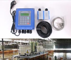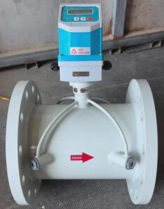
A Practical Guide for Industry Professionals Seeking Accurate, Non-Invasive Flow Diagnostics

This guide is written exclusively for OEM equipment and skid-mount manufacturers, instrument distributors and importers, EPC and system integrators, industrial terminal and MRO companies, and municipal and utility operators. Every scenario, number, and recommendation in this article reflects real-world challenges your customers face — not generic product descriptions.
1. Executive Insight: Why Non-Invasive Flow Measurement Is Now a Strategic Necessity
Water is becoming more expensive to source, treat, pump, and account for. At the same time, the infrastructure delivering it is aging faster than utilities can replace it. In that environment, every liter of water lost to an undetected leak, every kilowatt-hour wasted pumping water through a system running blind, and every compliance report filed on inaccurate flow data carries a direct financial cost.
The numbers are no longer abstractions. Globally, utilities lose 126 billion cubic meters of water every year to non-revenue water (NRW) — water that is produced, treated, and pumped but never billed. According to the World Bank, conservatively valued at USD 0.31 per cubic meter, this represents over $39 billion in annual global losses. In the United States alone, water losses cost utilities an estimated $6.4 billion in uncaptured revenues annually, according to Bluefield Research.
The response from utilities, industrial operators, and project engineers has been consistent: better flow data, faster. Not next month after a shutdown and meter installation. Now, on the live pipe, during normal operation, without a welding permit or a production loss.
That is exactly what portable ultrasonic flowmeters deliver.
Unlike traditional inline meters that require pipe cutting, process isolation, and hours of installation labor, a portable clamp-on ultrasonic flowmeter attaches to the outside of a live pipe in under 30 minutes. No fluid contact. No pressure interruption. No damage to the system being measured. The operator gets flow rate, velocity, and totalized volume in real time — and can move the instrument to the next measurement point the same morning.
For engineers, project managers, and asset operators who have historically relied on permanent instrumentation for every measurement decision, the implication is significant: portable ultrasonic flow measurement transforms water audits from scheduled, disruptive events into routine, on-demand diagnostics that can be performed anywhere in the system, at any time, by a single technician.
The global ultrasonic flow meter market was valued at USD 2.22 billion in 2026 and is projected to reach USD 3.27 billion by 2033 at a 5.7% CAGR, according to Coherent Market Insights. Within that market, portable and clamp-on instruments are the fastest-growing segment, driven precisely by the retrofit, audit, and diagnostic applications this guide addresses.
Jade Ant Instruments works with OEMs, EPCs, distributors, MRO teams, and utilities across more than 30 countries. The insights in this article are grounded in those application environments — not in catalog descriptions.
2. The Hidden Cost of Inaccurate Flow Data in Industrial and Municipal Systems
Before making the case for portable ultrasonic flowmeters, it is worth being specific about what inaccurate flow data actually costs — because the number is almost always larger than the people signing purchase orders realize.
What Inaccuracy Looks Like in the Field
Scenario 1: A regional water authority in Southeast Asia was billing customers based on flow data from turbine meters installed in the mid-1990s. Over time, rotor wear caused the meters to underread. The utility’s billing system continued charging customers based on understated consumption. Meanwhile, physical leakage in the distribution mains was masked by the measurement gap — the system appeared to be delivering water efficiently because the meters said so. By the time a portable ultrasonic audit was conducted at 45 district metered area (DMA) boundaries, the actual NRW was 28% of total production — nearly double what the degraded meter readings had suggested. Three previously hidden active leakage zones were identified within 60 days of restoring accurate flow data.
Scenario 2: A paper mill running effluent monitoring on 22 points using insertion electromagnetic probes was scheduled for quarterly electrode cleaning because the fiber and filler concentration in the effluent coated the probes within 6–8 weeks, causing calibration drift of 8–12%. This drift was not flagged automatically — it accumulated silently. Environmental compliance reports filed during drift periods contained flow data that was 8–12% inaccurate. The risk: a regulatory audit that could impose fines or trigger additional monitoring requirements.
Scenario 3: A wastewater treatment plant running backwash cycles on sand filters using a fixed timer — not actual flow data — was backwashing too frequently. Without accurate flow measurement on the backwash lines, the plant operators had no reliable signal to indicate when filters were actually loaded to their practical limit. The result: excess backwash water consumption estimated at 12–18% above optimum, and unnecessary chemical usage in the backwash cycle.
All three scenarios share the same root cause: measurement gaps where accurate, real-time flow data was either unavailable, degraded, or never installed. Portable ultrasonic flowmeters resolve all three — without shutting down the system, modifying the pipe, or waiting for a capital project approval.
The Compliance Dimension
In regulated industries — municipal water, wastewater discharge, food processing, pharmaceutical manufacturing — flow measurement is not optional. It underpins environmental discharge permits, billing contracts, process validation records, and energy management certifications like ISO 50001.
Inaccurate flow data in these contexts is not just an operational inconvenience. It is a compliance liability. A utility that cannot demonstrate accurate flow measurement at DMA boundaries loses the evidentiary basis for its NRW management program. A food plant that cannot verify CIP water volumes loses the validation record that supports product safety assurance.
Portable ultrasonic flowmeters function as independent reference instruments — capable of verifying whether fixed meters are reading accurately, whether backwash cycles are consuming the designed volume, and whether a new installation is performing to specification before the commissioning certificate is signed.
3. How Portable Ultrasonic Flowmeters Work: Science Made Simple for Engineers and Decision-Makers
The physics behind portable ultrasonic flowmeters is well understood, but the application detail — what determines accuracy in the field, and what causes errors — is where most purchasing decisions go wrong.
The Transit-Time Principle
The dominant technology in portable ultrasonic flowmeters for water and wastewater applications is transit-time measurement (also called “time-of-flight”). Here is how it works in plain terms:
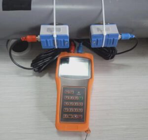
Two piezoelectric transducers — devices that convert electrical signals into ultrasonic pulses (high-frequency sound, typically 0.5 to 4 MHz, far above human hearing) — are clamped to the outside of the pipe. They alternate between transmitting and receiving. One pulse travels con the flow (downstream), and one travels against it (upstream).
Because sound travels faster in the direction of fluid flow than against it, the downstream pulse arrives slightly earlier than the upstream pulse. The meter measures this time difference — often in nanoseconds — and converts it into fluid velocity:
$$v = \frac{D \cdot \Delta t}{2 \cdot L \cdot \cos\theta}$$
Where:
- $$v$$ = fluid velocity (m/s)
- $$D$$ = pipe inner diameter (m)
- $$\Delta t$$ = transit-time difference (seconds)
- $$L$$ = acoustic path length between transducers (m)
- $$\theta$$ = angle of the ultrasonic beam relative to the pipe axis
Volumetric flow rate is then calculated by multiplying velocity by the pipe’s cross-sectional area — a value the operator enters based on measured pipe dimensions.
Definition — Piezoelectric transducer: A device that converts electrical energy into mechanical vibration (ultrasonic pulse) and vice versa. In clamp-on meters, these are pressed against the outside of the pipe wall with an acoustic coupling compound to transmit sound through the pipe into the fluid.
Clamp-On Operation: What Happens During Installation
The installation sequence for a portable clamp-on ultrasonic flowmeter on a live pipe:
- Measure the pipe: Record the outside diameter (OD) with a pi tape or vernier caliper, and measure wall thickness with an ultrasonic thickness gauge. Enter both into the transmitter.
- Select transducer spacing: The transmitter calculates the correct distance between the two transducers based on pipe geometry and the acoustic properties of the pipe material and fluid. The operator moves the transducers to the calculated positions on the pipe.
- Apply couplant and clamp: Acoustic couplant gel — a thick, viscous compound that fills microscopic air gaps between the transducer face and the pipe surface — is applied, and the transducers are clamped securely.
- Check signal quality: The transmitter displays a Signal Quality Index (SQI) — typically 0 to 100% — indicating how well the ultrasonic signal is passing through the pipe wall and fluid. An SQI above 60% indicates a reliable measurement. Below 50%, the location should be moved or investigated.
- Read and log: Once signal quality is confirmed, the meter begins displaying flow rate, velocity, and totalized volume in real time. Most professional portable units log data continuously with timestamps for post-survey analysis.
The entire process takes 20 to 45 minutes on a new pipe location, and under 10 minutes on a location the operator has measured before.
What Affects Accuracy in the Field
No portable ultrasonic meter achieves its specified accuracy automatically. Three factors determine whether a field measurement is reliable:
Pipe condition: The acoustic signal passes through the pipe wall before entering the fluid. Heavy internal corrosion (tuberculation), rubber or bitumen linings with an air gap, and severely variable wall thickness all attenuate or scatter the signal. Heavily corroded cast iron mains — common in aging municipal systems — can reduce signal quality to the point where meaningful measurement is not possible without moving to a better pipe section. A Signal Quality Index check resolves this in minutes.
Straight-run pipe: Like all velocity-based meters, clamp-on transducers need a minimum length of undisturbed, straight pipe to produce a symmetric velocity profile. The standard minimum requirement is 10 pipe diameters (10D) of straight pipe upstream and 5D downstream of the measurement point, free from bends, valves, pumps, or diameter changes. Installing 3D downstream of a 90° elbow introduces velocity swirl that can cause errors of 5–15%.
Fluid type and condition: Transit-time meters require a relatively clean fluid. In clean water, treated effluent, or light industrial fluids, ±0.5% to ±1.0% accuracy is achievable under ideal conditions. In fluids with suspended solids above 2–3% by volume, or with significant entrained air, transit-time signals are attenuated and a Doppler ultrasonic meter is the correct choice instead.
Definition — Doppler ultrasonic meter: A flow meter that measures the frequency shift of ultrasonic signals reflected off suspended particles or gas bubbles moving with the fluid. Requires a minimum concentration of reflectors to function. Best for raw sewage, activated sludge, mining slurry, and aerated liquids. Accuracy typically ±2%–±3%.
No Process Interruption: Why This Changes Everything
The defining operational advantage of clamp-on portable ultrasonic measurement is that the pipe is never opened, tapped, or cut. Pressure is maintained. Flow is uninterrupted. No isolation valves are operated, and no hot work permits are required.
For a municipal utility that cannot interrupt drinking water service, this is a prerequisite, not a convenience. For an industrial facility where shutting down a process line triggers a cascade of permit and restart procedures, it is a direct cost saving measured in hours and thousands of dollars. For an EPC commissioning a new wastewater plant, it means flow verification can begin on the day the team arrives on site — before any permanent instruments have been installed and calibrated.
4. Solving Critical Pain Points: 5 High-Impact Applications

This is where portable ultrasonic flowmeters stop being a technology story and start being a business tool. Each of the five applications below represents a recurring, high-value problem that your customers — OEMs, EPCs, utilities, MRO teams, or distributors — face regularly.
Application 1: Well Discharge Verification
The problem: A municipality draws groundwater from 12 production wells. Each well has a submersible pump with a rated discharge capacity. After 5 years of operation, the utility’s energy costs per cubic meter of water produced have risen 18%, but the flow totals from the older mechanical meters on the wellheads appear unchanged. No one knows whether the pumps are underperforming, the meters are underreading, or both.
The portable solution: A field team installs a portable transit-time clamp-on meter on the discharge pipe of each well — one location per hour — and records flow rate and velocity against the pump’s rated performance curve. Within a day, the survey reveals three wells producing 22–31% below rated discharge at the same energy input. Two are attributable to pump impeller wear; one to a partially closed gate valve that had been left in error.
The value: Without the portable survey, the utility would have continued operating degraded wells at full energy cost, or commissioned an expensive inline meter installation to diagnose the problem. With portable flow data in hand, the maintenance team can prioritize pump rehabilitation on evidence — not assumption — and verify improvement after each repair.
Key technical note: Well discharge verification requires measuring in the rising main above the pump, where the pipe is typically carbon steel or ductile iron in good condition — ideal for transit-time clamp-on measurement. Ensure at least 10D of straight run above the pump check valve before placing transducers.
Application 2: Backwash Water Monitoring
The problem: A surface water treatment plant operates 8 granular media filters. Backwash cycles are triggered on a fixed 48-hour timer regardless of actual filter loading. The plant manager suspects some filters are being backwashed earlier than necessary, consuming treated water and generating additional sludge handling costs. But there is no flow measurement on the individual backwash lines.
The portable solution: A portable clamp-on meter is installed on each backwash line in sequence during a one-week survey. The data shows that filter backwash volumes range from 12 m³ to 47 m³ per cycle across the 8 filters — a 4× variation that the fixed timer cannot reflect. Heavily loaded filters are being flushed adequately; lightly loaded filters are being over-backwashed.
The value: Switching from time-based to flow-based backwash control — using the portable survey data to calibrate the new setpoints — reduces total backwash water consumption by an estimated 28%. For a plant backwashing 8 filters at 30 m³ per cycle, 48-hour intervals, that represents approximately 4,032 m³ per month of avoidable treated water consumption eliminated.
Key technical note: Backwash lines are typically large-diameter, short-duration flows — low velocity during the cycle start, rising to peak, then decaying. Portable meters with a fast response rate (update interval ≤ 1 second) and totalizing function capture the full cycle volume accurately for commissioning new control logic.
Application 3: Hidden Leak Detection in Pressurized Lines
The problem: A distribution network manager receives customer complaints about low pressure in a specific zone. The zone input meter shows normal flow. No surface evidence of leakage exists. The pipe is buried under a road surface with no access points.
The approach — flow differential leak survey: The portable flowmeter is deployed at multiple points around the suspected zone boundary during minimum night flow (MNF) — typically 2:00 AM to 4:00 AM, when legitimate consumption is lowest and the flow signal of a leak is clearest.
If all legitimate outlets in the zone are closed or at minimum use, any sustained positive flow reading on a zone inlet indicates a leak. By comparing flow measurements at the zone boundary, the sub-zone boundary, and any branching connections, the leak can be triangulated to a specific pipe segment without opening the ground.
Real-world data: Según Badger Meter’s NRW reduction resources, accurate minimum night flow measurement is the single most impactful diagnostic step in any NRW reduction program. A sustained minimum night flow above 1.5 liters per minute per service connection is a reliable indicator of active leakage in a well-metered zone.
The value: Locating a leak with flow differential survey costs a field team 4–8 hours and the cost of a portable meter deployment. Excavating randomly to find the same leak — the alternative — can cost $15,000 to $60,000 in road opening, pipe exposure, and surface reinstatement per excavation event.
Application 4: Verification of Fixed Meter Accuracy
The problem: A utility billing customers through fixed electromagnetic meters on large commercial accounts has received billing disputes from two large industrial customers. Both claim their consumption is being overstated. The utility has no independent reference to check the fixed meters without removing them from service — which would require a full shutdown and recalibration that takes weeks.
The portable solution: A portable transit-time clamp-on meter is installed upstream of the suspect fixed meter under stable flow conditions. After a 30-minute stabilization period, the portable reading is compared against the fixed meter reading at matching flow conditions. If the two agree within ±1%, the fixed meter is operating within acceptable tolerance. If the portable reads consistently lower, the fixed meter is over-reading — and the utility has documented evidence to act on.
Key technical note: For meter verification to be credible, the portable meter must be installed with proper straight-run (10D upstream, 5D downstream), on pipe in good condition, and with a documented calibration certificate. This is not the same as ad hoc flow reading — it is a structured reference comparison that produces defensible evidence.
Definition — Calibration certificate: A document issued by the manufacturer or an accredited calibration laboratory confirming that the meter was tested against traceable reference standards (typically NIST in the US, or equivalent national standards) and found to measure within its specified accuracy. Essential for any meter used as a reference instrument.
Application 5: Temporary Flow Measurement During Maintenance or Upgrades
The problem: An EPC contractor commissioning a new water treatment plant needs to verify that each process stream — raw water intake, filter feed, clarifier underflow, treated water output — is delivering the designed flow rate before the performance guarantee can be signed off. Permanent meters have been specified for some points but not all, and several of the permanent meters have not yet been calibrated.
The portable solution: The EPC team uses a portable clamp-on kit to verify flow at every process measurement point during commissioning — including points where permanent meters are not yet installed or not yet calibrated. Each measurement is logged with timestamp, pipe location, and signal quality data, and submitted as part of the performance test documentation.
The value: Using a portable kit for commissioning verification allows the EPC team to identify flow shortfalls — underpowered pumps, valve settings, or piping design errors — before the client accepts the facility. Discovering that a filter feed pump is delivering 18% below design at commissioning, rather than after 12 months of underperforming operations, saves the cost of a post-acceptance remediation claim.
5. Integration and Scalability: How OEMs and System Integrators Can Embed Value
OEM skid manufacturers and EPC system integrators face a specific challenge that end-users do not: they must guarantee performance before the system leaves their control.
OEMs: Factory Acceptance Testing and Skid Validation
A compact water treatment skid leaves the factory with a rated capacity of 45 m³/hour of potable water output. The OEM’s QA procedure calls for a factory acceptance test (FAT) that verifies actual flow at three load points — 25%, 75%, and 100% of rated capacity. Installing permanent calibrated meters on every flow point of a skid built for field service would add cost, weight, and potential maintenance liabilities for the end customer.
Portable clamp-on meters solve this cleanly. During FAT, the portable is clamped to the product water outlet and the backwash inlet in sequence, verifying actual flow at each test point against the design specification. The test report is generated from the portable meter’s logged data. After FAT, the portable meter is removed and prepared for the next skid.
Jade Ant Instruments supports OEM customers with portable meter kits configured to cover the pipe size ranges used in their skid designs — from DN25 to DN300 in most compact water treatment applications — along with calibration certificates that satisfy the documented evidence requirements of ISO 9001-compliant FAT procedures. The clamp-on non-invasive flow meter guide outlines OEM-specific integration approaches in detail.
For skid-mount OEMs, the additional advantage is pipe-size flexibility. A single portable kit with three transducer sets covers the DN25, DN50, and DN100 pipes common in compact skid designs — replacing what would otherwise require three separate permanent meter installations to verify.
EPCs: Commissioning Verification and Performance Guarantees
EPC contracts on water and wastewater projects routinely include performance guarantee clauses tied to specific flow rates at defined measurement points. Before the project can be handed over and the final payment milestone triggered, actual flow at those points must be verified against the guaranteed values.
Portable clamp-on meters give EPC teams the ability to measure at any point in the system — including points where permanent meters are not yet installed or calibrated — on the first day of commissioning. This is not a compromise solution; it is a deliberate commissioning strategy that compresses the testing timeline.
For a wastewater treatment project with 18 process flow measurement points, deploying a single portable kit across all 18 points over two days is faster and less expensive than waiting for 18 permanent meters to be installed, calibrated, and verified individually. The portable data is used to identify and resolve performance shortfalls during commissioning, and the permanent meters — once installed — are verified against the portable reference before final handover.
El flow meter installation best practices guide from Jade Ant Instruments covers the commissioning verification protocol, including straight-run verification and signal quality documentation for both portable and permanent meter installations.
System Integrators: Audit-as-a-Service
For system integrators managing ongoing service contracts with municipal utilities or industrial clients, a portable ultrasonic flowmeter creates a recurring revenue opportunity: audit-as-a-service.
A structured annual flow audit — covering all fixed meter performance verification, NRW boundary measurement, and pump efficiency assessment — delivers concrete findings that justify the service contract renewal and position the integrator as a strategic operational partner rather than a reactive maintenance contractor.
The service requires one calibrated portable kit, a field technician trained in clamp-on measurement and data interpretation, and a structured reporting template that translates raw flow data into operational recommendations. Margins on audit services typically run 40–60% — significantly higher than on equipment supply alone.
6. Maximizing ROI: Cost Savings for Municipalities and Industrial End-Users
The investment case for portable ultrasonic flowmeters is compelling across customer segments — but the numbers need to be specific to be persuasive.
Water Loss Reduction: The Utility Case
| Metric | Before Portable Audit | After Portable Audit |
|---|---|---|
| NRW rate | 28% of production | 14% of production |
| Daily production | 50,000 m³/day | 50,000 m³/day |
| Daily NRW volume | 14,000 m³/day | 7,000 m³/day |
| Daily revenue recovery | — | 7,000 m³ × $0.45/m³ = $3,150 |
| Annual revenue recovery | — | $1,149,750 |
| Portable meter kit cost | — | $4,500–$8,000 |
| Payback period | — | < 3 days of revenue recovered |
These numbers are based on a regional utility with 50,000 m³/day production and a wholesale water value of USD $0.45/m³ — conservative for most OECD water systems. In water-scarce regions where the effective cost of treated water is higher, the recovery value compounds further.
Energy Savings: The Industrial Case
Pump systems account for approximately 20% of global industrial electricity consumption, and the majority of process pump systems operate less efficiently than their design point due to flow measurement gaps. A plant manager who cannot accurately measure flow through a cooling tower circuit cannot optimize the pump speed against actual demand — and defaults to conservative (high-energy) operating settings.
A portable flow survey on a 75 kW cooling water pump running 8,760 hours per year at $0.10/kWh revealed the pump was running at 110% of actual demand — an excess energy cost of:
$$\text{Excess Cost} = 75 \text{ kW} \times 0.10 \times (1.10^3 – 1.0) \times 8,760 \approx $19,200 \text{ per year}$$
(Fan/pump law: power scales with the cube of speed/flow ratio.)
Correcting the VFD setpoint based on accurate portable flow data recovered approximately $19,200 per year on a single pump circuit — with a $5,500 portable meter investment.
Comparing Portable vs. Invasive Alternatives
| Cost Category | Portable Clamp-On Survey | Insertion Meter (Hot-Tap) | Full Inline Replacement |
|---|---|---|---|
| Equipment cost | $4,500–$8,000 (reusable kit) | $3,000–$8,000 per point | $5,000–$15,000 per point |
| Installation labor | $200–$500 per day | $1,500–$4,000 per point | $2,500–$8,000 per point |
| Process shutdown required? | No | Partial (hot-tap valve) | Yes (full isolation) |
| Pipe modification? | Ninguno | Drilling + fitting | Cutting + flanging |
| Points covered per day | 6–12 (one kit) | 1–2 | 1 |
| Redeployable? | Yes — across any site | No | No |
| Calibration frequency | Annual | 2–3 years | 2–5 years |
The portable option’s key financial advantage is reusability. A $6,000 portable kit deployed across 10 survey points costs $600 per point in equipment amortization. An insertion meter installation at $5,000 per point costs the same — but the portable delivers results the same day and can be redeployed tomorrow.
7. Best Practices for Reliable, Repeatable Measurements
Accurate portable ultrasonic flow measurement is not automatic. The single most common cause of field measurement error is not a hardware deficiency — it is a procedure gap. Here is the step-by-step protocol that professional field teams follow.
Step 1: Pipe Identification and Dimension Measurement
Never use nominal pipe size from a drawing. Measure the actual outside diameter with a pi tape or vernier caliper at the intended transducer location. Verify wall thickness with an ultrasonic thickness gauge at 3–4 points around the pipe circumference. A 2mm OD error on a DN100 pipe introduces approximately 4% velocity offset that no calibration can correct.
Confirm the pipe material (carbon steel, stainless steel, PVC, HDPE, cast iron). Check for internal linings — cement, rubber, or epoxy — as these affect acoustic transmission. Rubber-lined pipes are generally incompatible with standard transit-time clamp-on measurement.
Step 2: Location Selection
Apply the straight-run rule: at minimum 10D of straight pipe upstream and 5D downstream, free from bends, valves, reducers, or pumps. In cramped plant environments where 10D is unavailable, increase the minimum to 15–20D if the nearest upstream disturbance is a 90° elbow or a partially open valve. Document the actual upstream and downstream distances in the survey record.
Avoid locations above pump volutes, directly downstream of check valves, or on vertical risers where the pipe may not be full during low-flow periods.
Step 3: Surface Preparation and Couplant Application
Remove paint, rust, or debris from the pipe surface at the transducer contact points. A flat, clean surface is essential for consistent acoustic coupling. Apply a generous layer of acoustic couplant gel — not ordinary grease or petroleum jelly — to both transducer faces before clamping. Couplant fills microscopic surface irregularities that would otherwise create air gaps reflecting the ultrasonic signal before it enters the pipe.
In cold weather applications (below 5°C), use a couplant rated for low-temperature viscosity — standard gels thicken and lose effectiveness below 0°C.
Step 4: Signal Quality Verification
Before recording any flow data, confirm the Signal Quality Index (SQI) is above 60%. An SQI of 60–80% indicates good coupling and reliable measurement. An SQI above 80% is excellent. Below 50%, do not proceed with measurement — investigate pipe condition, couplant application, or move to a better pipe location.
Common causes of low SQI:
- Air gap between transducer and pipe (insufficient couplant)
- Heavy internal pipe corrosion or tuberculation
- Internal lining creating acoustic mismatch
- Incorrect transducer spacing
- Pipe not full of liquid (air pocket or partially drained pipe)
Step 5: Parameter Entry and Zero Check
Enter pipe OD, wall thickness, pipe material, and fluid type accurately. An incorrect speed-of-sound entry for the fluid introduces a systematic error that persists throughout the measurement. Most portable meters have preset fluid libraries for water, seawater, diesel, and common chemicals — select the closest match and verify against the meter’s displayed speed-of-sound reading.
At zero flow (close an upstream valve if possible), confirm the meter reads zero ± 0.01 m/s. A non-zero reading at zero flow indicates grounding noise, pipe vibration, or signal interference — which must be resolved before flow measurement begins.
Step 6: Data Logging Setup
Configure the logging interval based on the measurement objective:
- Leak detection minimum night flow: Log every 1 minute for a minimum of 2 hours
- Pump performance verification: Log every 5 seconds during the ramp-up and steady-state period
- Backwash cycle monitoring: Log every 1 second to capture the full cycle transient
- DMA boundary metering: Log every 15 minutes for 24 hours minimum
Export logged data to CSV or PDF using the meter’s USB or Bluetooth connection. Time-stamp every record with GPS location if the meter supports it — this is invaluable when producing a multi-point survey report.
Common Errors to Avoid
| Error | Cause | Impact | Prevention |
|---|---|---|---|
| Using nominal OD instead of measured OD | Skipping pipe measurement | 2–5% systematic velocity error | Always measure with pi tape |
| Insufficient straight run | Placement near elbows or valves | 5–15% error from swirl | Verify 10D upstream before placement |
| Poor couplant application | Thin or missing gel layer | Low SQI, unstable reading | Apply generous layer to both transducers |
| Incorrect pipe material entered | Guessing from appearance | Speed-of-sound error | Verify material from system drawings |
| Measuring on partially full pipe | Vertical riser, gravity main | Air in signal path, false low reading | Choose a point where pipe stays full |
| Ignoring SQI below 50% | Accepting first reading | Large random errors | Move to a better location and recheck |
8. Selecting the Right Portable Ultrasonic Flowmeter: Key Technical Criteria
Not all portable clamp-on flowmeters are equivalent. The right selection depends on the specific applications your customers face. Here is the evaluation framework used by professional specifiers.
Pipe Size Range
Most portable kits come with two or three transducer sets covering different pipe size ranges. A standard professional kit covers DN20 to DN300 with one set of transducers, and DN300 to DN3000 with a second larger-format set. Confirm that the kit covers the full range of pipe sizes your customer will encounter — a kit that only covers to DN300 is useless on a DN600 transmission main.
Accuracy Specification
Look for ±1.0% of reading or better for transit-time models on clean water. Be cautious of specifications quoted as “% of full scale” rather than “% of reading” — at low flow rates, % of full scale accuracy degrades significantly. For a meter rated at ±1% FS with a 10 m/s full scale, measuring at 0.5 m/s gives an effective uncertainty of ±20% of reading.
Battery Life
Field surveys require uninterrupted operation. A portable meter deployed for minimum night flow monitoring at a remote pump station must run for at least 6–8 hours without recharging. Professional portable meters typically offer 16–30 hours of continuous operation. Verify this against the planned survey duration — and check whether the battery is field-replaceable in case of longer deployments.
Data Logging Capacity
Minimum requirement: 100,000 data points with user-configurable time intervals from 1 second to 60 minutes. Data should be exportable in CSV format as a minimum, with PDF report generation as a plus. Some professional models offer 12 million data points — enabling continuous 24/7 monitoring over weeks without offloading data.
Connectivity
At minimum: USB data transfer. Better: Bluetooth for real-time data streaming to a smartphone or tablet, allowing the operator to view the live trend on a tablet while the transducers are mounted on an inaccessible pipe section. Some advanced models support Modbus RS-485 output, enabling connection to a temporary data logger or SCADA interface during commissioning.
Ruggedness and IP Rating
Field instruments get dropped, rained on, and submerged in muddy trenches. IP67 is the minimum acceptable rating for serious field use — fully dust-tight and capable of withstanding 30-minute immersion to 1 meter. IP68 is better for applications near flooded pump stations or below-grade valve chambers. Verify that the rating applies to both the transmitter (main unit) and the transducer connectors — the most common failure point in poorly rated portable instruments.
Pipe Material Compatibility
| Pipe Material | Transit-Time Compatible? | Notas |
|---|---|---|
| Carbon steel | ✅ Yes | Standard couplant; V or Z configuration |
| Stainless steel (304/316) | ✅ Yes | Ideal surface condition |
| Ductile iron / cast iron (new) | ✅ Good | Check wall thickness variation |
| Cast iron (heavily tuberculated) | ⚠️ Test first | May require Z-configuration or relocation |
| HDPE | ✅ Yes | Use correct couplant for plastic |
| PVC / CPVC | ✅ Yes | Verify SDR rating for wall thickness |
| Cement-lined steel | ⚠️ Reduced | Cement attenuates signal; verify SQI |
| Rubber-lined steel | ❌ Generally incompatible | Air-gap lining reflects signal |
| GRP / FRP (fiberglass) | ⚠️ Test required | Multi-layer structure reduces signal |
| Concrete | ❌ Not recommended | Highly attenuating; aggregate scatters signal |
Software Compatibility
Check that the portable meter’s companion software runs on current Windows, iOS, or Android platforms. Older portable meters with outdated software may not run on Windows 11 or current macOS versions — a practical problem when trying to download a survey from a 5-year-old instrument on a current laptop.
9. Supporting Your Business: How Distributors and Importers Can Drive Adoption
For distributors and importers, portable ultrasonic flowmeters represent a fundamentally different commercial opportunity than selling fixed instrumentation.
Why Portables Carry Higher Margins
Fixed instrumentation is commoditized. Customers can specify a DN100 electromagnetic meter, get three quotes, and buy on price. A portable ultrasonic flowmeter kit is a professional tool — and professional tools are sold on capability, support, and outcome, not on price alone.
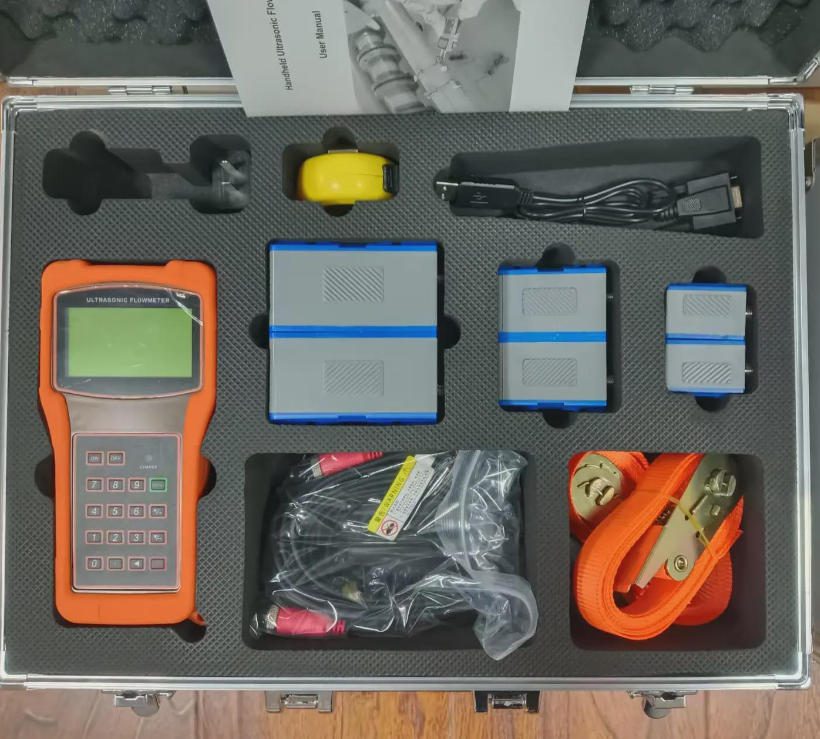
A complete portable audit kit — flowmeter, transducer sets, carrying case, couplant supply, calibration certificate, and application training — can be positioned at $8,000–$15,000 for a professional-grade system. Gross margins on value-bundled kits typically run 35–55%, compared to 15–25% on standard fixed instrumentation. The support element — application training, demo units, and site survey assistance — justifies premium pricing and creates switching costs that protect the relationship.
Building a Demo Unit Program
The single most effective sales tool for portable flowmeters is a demonstration on the customer’s own pipe. A customer who has watched a portable meter installed and running on their DN200 water main in 25 minutes, showing real flow data, is far more likely to purchase than a customer who has reviewed a datasheet.
Build a demo unit program: maintain one fully calibrated portable kit as a loan unit that customers can trial in the field for 48–72 hours. Track which demo units convert to sales. Most distributors running structured demo programs report conversion rates of 40–65% — among the highest for any instrumentation product category.
Service Bundles That Create Recurring Revenue
Structure portable flowmeter sales as the foundation of a recurring service relationship:
- Calibration renewal: Annual calibration of the portable kit, performed by the distributor’s in-house calibration service or a certified partner. Calibration service charges of $600–$1,200 per kit per year are readily justified by customers who use the meter for compliance-related measurements.
- Couplant supply: Professional-grade acoustic couplant is a consumable. A customer running 50 survey points per month goes through a 300mL tube of couplant every 3–4 months. Supplying branded couplant keeps the distributor engaged in the customer’s ongoing operations.
- Application support packages: Annual application engineering support — helping customers plan surveys, interpret results, and write reports — adds value that competitors cannot easily replicate. Price this at $1,500–$3,000 per year per customer.
- Training programs: Half-day or full-day training sessions for customer field teams, covering measurement technique, data interpretation, and report writing. Charge $500–$1,500 per session. Trained technicians become advocates for the technology within their organizations.
El Jade Ant Instruments ultrasonic flow meter buying guide provides distributors with detailed specification tables and application matching criteria that support structured pre-sale technical conversations with utilities, EPCs, and industrial end-users.
10. Future-Proofing Water Infrastructure: The Role of Portable Diagnostics in Smart Water Networks

The water industry is investing heavily in digital transformation — SCADA upgrades, digital twin models, cloud-based analytics, and predictive maintenance platforms. Portable ultrasonic flowmeters are not peripheral to this transition. They are an essential enabler of it.
Filling the Gaps in Permanent Monitoring Networks
No matter how extensive a utility’s permanent instrumentation network, there will always be points where continuous monitoring is not installed — due to cost, access constraints, or the decision that periodic rather than continuous measurement was sufficient at the time. These unmeasured points become the blind spots in the digital twin: locations where the model makes assumptions rather than using real data.
Portable flow meters fill these gaps on demand. When a distribution model predicts that a specific zone boundary should see 240 m³/hour at peak demand, and the utility wants to verify that prediction before commissioning a new pressure zone boundary, a portable meter deployed at that point for 48 hours provides the validation data. The digital twin is updated with real measurements rather than hydraulic model estimates — improving its predictive accuracy for the entire network.
SCADA Validation and Calibration Chain
Fixed meters reporting to SCADA are only as accurate as their calibration state. A fixed electromagnetic meter that has not been recalibrated in 5 years may have drifted 2–4% from its original calibration — enough to introduce meaningful error into billing calculations or energy management reports.
Portable clamp-on meters, used as independent reference instruments, establish the calibration chain from field conditions back to traceable standards. The verification protocol is straightforward: install the portable alongside the fixed meter under stable flow conditions, compare readings over 30 minutes, and document the offset. If the offset is within ±1%, the fixed meter is performing acceptably. If not, a maintenance work order is triggered with specific measured evidence — not a maintenance technician’s subjective assessment.
This protocol can be performed on every significant fixed meter in a utility’s network on an annual rotation — providing a continuous, documented calibration verification record without removing any meter from service.
Connecting Portable Data to Digital Platforms
Modern portable flowmeters generate timestamped, GPS-tagged flow records that are directly importable into GIS platforms, hydraulic modeling software (WaterGEMS, InfoWorks ICM, EPANET), and cloud-based SCADA systems. The data is no longer trapped in a field technician’s notebook — it becomes a live input to the network model.
As documented in a 2025 remote water monitoring case study by ICPDAS, connecting portable and permanent flow measurement data to cloud dashboards enabled a water authority to identify three leakage zones within 60 days of commissioning — reducing inspection costs by approximately 40% compared to traditional manual survey methods.
The integration pathway for most utilities:
- Export portable meter data (CSV) after each survey
- Import to hydraulic model or GIS platform and update the relevant measurement nodes
- Compare modeled vs. measured flows to identify anomalies
- Update predictive maintenance schedules based on fixed meter drift trends identified during portable verification
- Feed anomaly alerts to SCADA for operations team awareness
Jade Ant Instruments’ ultrasonic versus magnetic flow meters guide for clean water covers digital integration protocols for both portable and permanent ultrasonic meters, including Modbus and HART output configuration for SCADA connectivity.
📺 Video Resource: How Portable Clamp-On Ultrasonic Flowmeters Work
Understanding the technology in 10 minutes — transit-time vs. Doppler, clamp-on installation, and real-world applications explained for engineers and field teams.
▶️ Watch: Doppler vs Transit Time — Ultrasonic Flow Meters Explained
Quick Reference: Portable Ultrasonic Flowmeter Selection Guide
| Solicitud | Fluid Condition | Recommended Principle | Typical Accuracy | Minimum Pipe Size | Key Feature to Specify |
|---|---|---|---|---|---|
| Municipal water audit (DMA metering) | Clean, treated water | Transit-time | ±0.5%–±1.0% | DN50 | Data logging; 20+ hr battery |
| Well discharge verification | Clean groundwater | Transit-time | ±0.5%–±1.0% | DN50 | High turndown for low-flow |
| Backwash line monitoring | Turbid filter water | Transit-time | ±1.0%–±1.5% | DN80 | 1-second log rate; totalizing |
| Raw sewage / lift station | High solids, aerated | Doppler | ±2%–±3% | DN100 | Dual-path Doppler transducer |
| Industrial effluent (paper mill) | Suspended fiber/filler | Doppler | ±2%–±4% | DN100 | Rugged IP68 housing |
| Fixed meter verification | Clean process water | Transit-time | ±0.5%–±1.0% | Any | Calibration certificate required |
| EPC commissioning verification | Clean water/process | Transit-time | ±0.5%–±1.0% | DN25–DN600 | Multi-pipe-size transducer kit |
| Pump energy audit | Clean liquid | Transit-time | ±0.5%–±1.0% | DN40+ | Velocity display; fast update rate |
| Large main / transmission | Clean water | Transit-time (Z-mode) | ±1.0%–±2.0% | DN300–DN3000 | Large-pipe transducer set |
Key Technical Terms Glossary
Transit-time (time-of-flight): The ultrasonic measurement principle that calculates flow velocity from the time difference between pulses sent with and against the flow direction. Works best in clean liquids. Typical accuracy: ±0.5%–±1.5%.
Doppler ultrasonic: The measurement principle that measures frequency shift of signals reflected off particles or bubbles. Works in fluids with suspended solids or gas. Typical accuracy: ±2%–±3%.
Signal Quality Index (SQI): A 0–100% indicator of received signal strength and reliability. Above 60%: measurement is reliable. Below 50%: investigate pipe condition and transducer coupling before trusting readings.
Non-revenue water (NRW): The gap between water produced by a utility and water billed to customers — including leakage, meter errors, and unauthorized use. The global average is 30–40% in developing markets.
Acoustic couplant: A viscous gel applied between the transducer face and the pipe surface to eliminate air gaps that would reflect the ultrasonic signal before it enters the pipe.
Straight-run requirement: The minimum length of straight, undisturbed pipe needed upstream and downstream of the meter to produce a symmetric, measurable velocity profile. Typically 10D upstream and 5D downstream for clamp-on meters.
District Metered Area (DMA): A defined zone in a water distribution network with measured inlet and outlet flows, used for leak detection and NRW management.
Calibration certificate: A document confirming that a meter has been tested against traceable reference standards. Required for meters used as reference instruments in compliance or billing verification contexts.
Minimum Night Flow (MNF): The lowest flow rate recorded in a water distribution zone, typically between 2:00–4:00 AM, when legitimate consumption is at its lowest. A sustained positive MNF indicates active leakage.
Turndown ratio: The ratio of maximum to minimum measurable flow. A 100:1 turndown ratio means the meter maintains accuracy from 10 m/s down to 0.1 m/s — critical for systems with variable demand.
Digital twin: A virtual model of a physical system (e.g., a water distribution network) that uses real measured data to simulate performance, identify anomalies, and predict future behavior.
Preguntas frecuentes
1. How accurate are portable ultrasonic flowmeters compared to inline meters?
Modern transit-time portable clamp-on meters achieve ±0.5% to ±1.0% accuracy under optimal conditions — clean fluid, good pipe condition, adequate straight-run, and proper installation procedure. This is comparable to many fixed single-path inline meters used for process control and flow monitoring. The performance gap exists at the high-accuracy end: multi-path inline meters certified to AGA-9 or API MPMS Chapter 5.8 achieve ±0.15%–±0.25% for fiscal custody transfer — a specification that clamp-on portable meters cannot meet. For the diagnostic, audit, and verification applications described in this guide, ±1.0% is more than adequate.
2. Can I use a portable ultrasonic meter on coated, lined, or corroded pipes?
Yes, with important qualifications. Cement-lined steel, epoxy-lined steel, and moderately corroded carbon steel pipes are generally compatible — verify by checking the Signal Quality Index (SQI) after clamping the transducers. If SQI is above 60%, measurement will be reliable. Rubber-lined pipes are generally incompatible because the rubber creates an acoustic air gap that reflects the signal before it enters the fluid. Severely tuberculated cast iron — common in older municipal mains — can reduce SQI to the point where meaningful measurement is not possible at that location; moving 1–2 meters along the pipe often finds a better section. Heavily corroded pipes with wall thickness variation above 15% of nominal also reduce reliability.
3. Do I need to shut down the system to install the sensors?
No. This is the defining advantage of clamp-on portable ultrasonic measurement. Transducers are installed on the outside of a live, pressurized pipe using couplant gel and a clamping fixture. No valve operation, no pressure reduction, no hot work, no pipe penetration. The system continues operating normally during the entire installation, measurement, and removal process. A complete installation on a DN200 pipe takes 20–40 minutes from unboxing to first reading.
4. How do I detect a leak using a portable flowmeter?
The most reliable method is minimum night flow (MNF) survey. Install the portable meter at the inlet to a defined zone or sub-zone. Record flow continuously from 2:00 AM to 4:00 AM, when legitimate consumption is at its lowest. If the meter records a sustained positive flow when all outlets are closed or at minimum use, that flow represents leakage. Quantify the leak by comparing measured MNF against the expected background consumption (legitimate minimum use). For a zone with 500 connections, expected background MNF at 1.5 liters/connection/hour is 750 L/hr. A measured MNF of 3,200 L/hr indicates approximately 2,450 L/hr of active leakage — enough to justify targeted detection work. Use measurements at sub-zone boundaries to triangulate the leak to a specific pipe segment without excavation.
5. Can these devices measure dirty or aerated water?
Transit-time portable meters perform best in clean or lightly loaded water — up to approximately 2–3% suspended solids by volume. Above that threshold, or in fluids with significant entrained air, transit-time signals are attenuated and readings become unreliable. For these applications, a Doppler portable meter — or a dual-beam model that can switch between transit-time and Doppler modes — provides reliable measurement using the suspended particles or bubbles as reflectors. Most professional portable kits for wastewater and industrial use include both transit-time and Doppler operating modes, selectable from the menu based on fluid conditions observed in the field.
6. What pipe materials are compatible with clamp-on portable meters?
Compatible materials include carbon steel, stainless steel (304, 316), ductile iron, copper, brass, PVC, CPVC, HDPE, PP, PVDF, and most rigid thermoplastics. Problematic materials include rubber-lined pipes (air-gap lining reflects signal), bitumen-coated interiors, severely corroded steel with heavy tuberculation, and fiberglass/GRP (multi-layer composite structure attenuates signal). When pipe material is uncertain, perform a Signal Quality Index check immediately after transducer installation — this is the definitive field test and takes less than 2 minutes.
7. How long does a typical water audit take with a portable flowmeter?
A single well or pump discharge measurement takes 30–60 minutes from arrival to departure. A DMA boundary flow survey covering 8–12 measurement points typically takes 1–2 days of field work. A full system leak detection survey on a medium-sized distribution network (50–100 DMAs) with minimum night flow monitoring at each point is typically planned over 2–4 weeks, working 10–15 points per day. A complete filter backwash cycle survey at a water treatment plant — monitoring all filters in sequence — takes 3–5 days depending on the number of filter cells and the cycle frequency.
8. Can I log data over time for trend analysis?
Yes. Professional portable models support continuous data logging with user-configurable intervals from 1 second to 60 minutes. A unit with a 12-million-point logging capacity can record at 1-minute intervals for approximately 23 years without memory overflow. Data is exported via USB or Bluetooth to a PC or tablet in CSV format — directly importable into Excel, hydraulic modeling software, or SCADA data historians. Time-stamped records enable trend analysis: comparing MNF over 12 months reveals seasonal leakage patterns, gradual meter drift, or pipe condition changes that would be invisible from single-point measurements.
9. Are portable flowmeters suitable for custody transfer?
Not typically. Custody transfer — legally binding measurement for commercial transactions between trading parties — requires meters certified to specific metrological standards (OIML R 49 for water meters, AGA-9 for gas, API MPMS Chapter 5.8 for liquid hydrocarbons) with NIST-traceable calibration and approved installation configurations. Portable clamp-on meters do not currently meet these requirements. However, portable meters are widely accepted for audit and verification of fixed custody meters — providing documentary evidence that a fixed meter is or is not reading within acceptable tolerance. This is a valuable and legally defensible role, distinct from being the primary custody transfer instrument.
10. How do I verify the performance of a fixed flowmeter in the field?
Install the portable unit on the same pipe as the fixed meter — upstream or downstream of it, with adequate straight-run between the two to avoid mutual flow disturbance. Allow both meters to stabilize under steady flow conditions for 10–15 minutes. Compare the readings at multiple flow rates if possible. If the two meters agree within ±1–2%, the fixed meter is performing within acceptable tolerance. If the portable consistently reads lower or higher by more than 2%, the fixed meter has drifted and should be serviced or recalibrated. Document the comparison: record the flow rates compared, the agreement/disagreement, and the portable meter’s calibration certificate reference number. This creates a defensible maintenance record for regulatory or contractual purposes.
11. What training is required for field technicians?
Basic competency — setup, sensor placement, parameter entry, and data interpretation — can be achieved in 2–4 hours of structured training. This is sufficient for routine well surveys, DMA metering, and fixed meter verification on well-characterized pipe systems. Advanced proficiency — handling difficult pipe materials, troubleshooting low SQI, configuring Doppler mode for mixed-phase flows, integrating with SCADA outputs — requires additional application-specific training, typically 1–2 days. Jade Ant Instruments provides application engineering support and training for distributors and end-users, covering the full range of portable and fixed clamp-on meter applications. See the flow meter decision tree guide for a practical reference tool that field teams can use without deep fluid dynamics background.
12. Can I use the same device across multiple sites or industries?
Yes. A quality portable kit with multiple transducer sets covers DN25 to DN3000 — spanning compact OEM skid piping, medium-diameter water treatment plant headers, and large-diameter transmission mains in a single instrument. The same kit measures drinking water, treated effluent, cooling water, diesel fuel, and light industrial fluids simply by selecting the appropriate fluid properties in the meter menu. This versatility is the primary reason distributors and MRO teams invest in professional portable kits rather than application-specific fixed instruments — one instrument covers their entire customer base. The inline vs. clamp-on cost comparison guide from Jade Ant Instruments provides a detailed analysis of where portable instruments deliver superior value versus permanent installations.
13. How do I handle low-flow measurement challenges?
Low-flow measurement — below 0.1 m/s — is technically demanding for transit-time meters because the transit-time difference (Δt) at low velocity is very small (typically a few nanoseconds on a DN100 pipe), making it harder to distinguish from noise. Solutions include: specifying a dual-beam model with enhanced signal processing resolution (some professional models specify minimum detectable velocity of 0.01 m/s); ensuring the pipe is completely full with no air pockets during measurement (air pockets at the pipe crown create false low readings); and confirming the pipe’s Reynolds number is above the turbulent threshold (Re > 4,000) to ensure a stable, predictable velocity profile. In gravity-fed systems at very low flow, consider a Doppler meter if any particulate or bubble content is present — the Doppler signal does not depend on the smallness of Δt.
14. Is there a risk of signal interference from pumps or valves?
Yes. Pumps generate vibration in the pipe wall and in the fluid — particularly centrifugal pumps at off-design operating points (cavitation). Gate valves partially open create turbulent vortices that disrupt the velocity profile downstream. Both sources of disturbance increase signal noise and reduce measurement accuracy. The standard mitigation is to place transducers at the straight-run distances specified: at least 10D upstream and 5D downstream of any flow disturbance, including pumps, valves, elbows, and pipe diameter changes. In environments with significant pump vibration, use the meter’s signal averaging function (averaging window of 10–30 seconds) to reduce noise-induced reading fluctuation. If SQI remains low despite adequate straight-run, the pipe location itself may be experiencing resonant vibration — move 0.5–1.0m along the pipe to a less-resonant section.
15. Do you offer technical support and calibration services?
Yes. Jade Ant Instruments provides application engineering support for instrument selection, installation configuration, and troubleshooting across portable and fixed ultrasonic meter applications. Calibration services — including NIST-traceable recalibration with full uncertainty documentation — are available to support annual verification requirements for professional portable kits used in compliance and billing-verification contexts. Distributors and agents are supported with pre-sale technical consultation, demo unit programs, and application-specific training resources. For technical inquiries, product selection support, and calibration scheduling, visit Jade Ant Instruments or reach out directly to the regional application engineering team.
This guide was written exclusively for professionals who engineer, supply, integrate, operate, or maintain water and industrial fluid systems. Every figure cited and every application scenario described reflects real-world challenges — not marketing copy. Portable ultrasonic flow measurement works. The data proves it. The only question is how quickly your customers start using it.
Explore related technical resources from Jade Ant Instruments: