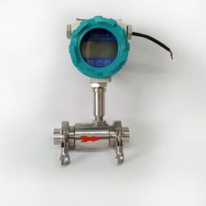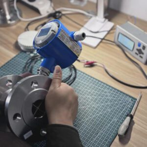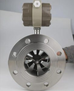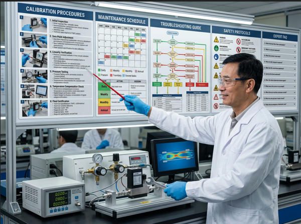
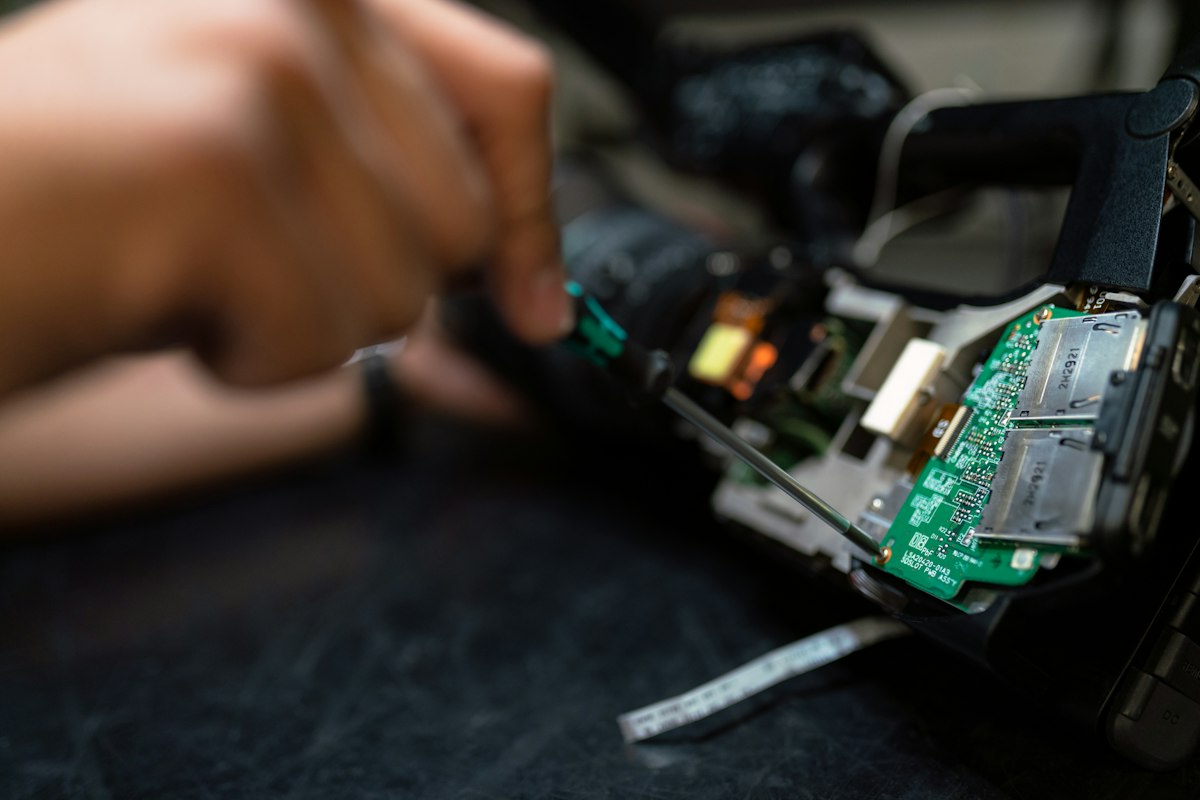
A Thermal Mass Flow Controller (TMFC) that drifts 2% off calibration on a semiconductor CVD tool — where process gas ratios determine wafer yield — can silently cost $50,000 per production run before anyone notices. Yet in practice, more than 40% of TMFC failures in industrial settings are caused not by hardware defects, but by skipped calibration checks, missed preventive maintenance, and unresolved zero-drift that accumulates over months. This guide changes that.
Whether you manage a gas delivery panel in a pharmaceutical synthesis lab, a compressed-air network across a food & beverage plant, or a multi-loop process control system in a refinery, the principles of TMFC calibration, maintenance, and troubleshooting are consistent. This guide covers all three — starting from first principles, progressing through hands-on procedures, and ending with a decision framework for when to recalibrate, clean, tune, or replace.
📘 Key Terms Defined
Understanding Thermal Mass Flow Controllers: Principles and Types

A thermal mass flow controller combines a calorimetric flow sensor, a PID control algorithm, and a proportional or solenoid control valve in a single compact body — making it the workhorse of precision gas delivery across semiconductor, pharmaceutical, and chemical process industries.
How TMFCs Measure Flow Using Calorimetric Principles
The calorimetric measurement principle works by exploiting a fundamental property of gases: flowing gas molecules carry heat energy with them. Inside a TMFC, a small-diameter bypass capillary tube (in capillary-type designs) or a MEMS chip (in micro-electromechanical designs) carries a fraction of the total gas flow past two temperature sensors placed symmetrically upstream and downstream of a heater element.
At zero flow, the temperature field around the heater is symmetrical — both sensors read the same temperature. As gas begins to flow, it carries heat toward the downstream sensor, creating a temperature differential (ΔT). The TMFC’s electronics measure this ΔT and convert it to a mass flow reading using the relationship: Mass Flow Rate = (Heater Power) / (Cp × ΔT), where Cp is the specific heat capacity of the gas. This is why the calibration is gas-specific: each gas has a unique Cp value.
Common TMFC Configurations and Models
| TMFC Type | Sensor Design | Typical Flow Range | الدقة | أفضل تطبيق |
|---|---|---|---|---|
| Capillary Bypass Thermal | Wound capillary tube with upstream/downstream RTDs | 0.5 sccm – 30 slm | ±0.5% Rd + 0.1% FS | Semiconductor process gas, lab research, pharma synthesis |
| MEMS Thermal (chip-based) | Micro-fabricated silicon chip with integrated heater and sensors | 0.014 mln/min – 200 slm | ±0.5% Rd + 0.1% FS | Ultra-low-flow gas, analytical instruments, precision dosing |
| Thermal Dispersion (insertion) | Probe inserted into pipe with heated tip and reference RTD | 0.1 – 3,000+ Nm³/h | ±1.0–2.0% FS | Large-bore industrial gas: compressed air, N₂ headers, biogas |
| Inline Thermal (small bore) | Full-bore design with sensors in-line with gas path | 0.1 – 500 Nm³/h | ±1.0% FS | Process gas monitoring, utility metering, HVAC control |
Key Terminology and Specifications
When evaluating a TMFC datasheet, these are the specifications that matter most in practice — and where misinterpretation most often leads to wrong procurement decisions:
- Accuracy: Always note whether specified as % of reading (proportional to actual flow — better at low flows) or % of full scale (fixed absolute error — worse at low flows). A 1% FS controller on a 500 sccm range has a ±5 sccm error whether you’re at 500 sccm or 10 sccm.
- Repeatability: Typically 2–5× tighter than accuracy. Matters more than accuracy in closed-loop control — a consistent offset can be compensated; random scatter cannot.
- Response time (T90): Time to reach 90% of setpoint after a step change. Ranges from <1 second (MEMS, fast PID) to 5+ seconds (large capillary designs). Critical for batch sequencing.
- Turndown ratio: Max/min measurable flow at spec. A 200:1 turndown on a 500 sccm controller means usable range down to 2.5 sccm.
- Leak integrity: Metal-sealed (VCR/VCO) designs for ultra-high purity or hazardous gases; elastomer-sealed designs for standard process gas service.
Calibration Fundamentals: When and Why to Calibrate

A properly equipped TMFC calibration bench includes a traceable primary or transfer standard (bubble meter, critical flow Venturi, or molbloc/molbox), a stable gas source at controlled pressure, temperature measurement, and a documented procedure aligned to ISO/IEC 17025 or equivalent.
Why Calibration Affects Accuracy and Repeatability
A TMFC that leaves the factory with ±0.5% accuracy does not stay at ±0.5% indefinitely. Three mechanisms cause calibration drift in the field:
(1) Sensor element aging: The resistance characteristics of the RTD or thermopile sensor elements change gradually with thermal cycling. A capillary TMFC seeing 50°C daily temperature swings (lab to process and back) may drift 0.1–0.3% FS per year from sensor aging alone. (2) Contamination: Trace moisture, oil aerosols, or particulates in the gas stream deposit on the sensor element, changing its apparent thermal resistance. Even 99.99% pure nitrogen can carry enough moisture to cause visible drift within 6 months in a poorly plumbed system. (3) Valve wear: The control valve seat and diaphragm experience repeated micro-cycling. A TMFC controlling at 50% of range may cycle its valve tens of thousands of times per day; over months, valve seat wear introduces offset between commanded and delivered flow.
Typical Calibration Intervals and Traceability Considerations
الـ industry standard calibration interval for TMFCs in process-critical applications is 6-12 شهراً, adjusted by application severity:
| نوع التطبيق | Recommended Interval | Rationale | Traceability Requirement |
|---|---|---|---|
| Semiconductor process gas (CVD, etch, implant) | 6 أشهر | Yield-critical; small drift = wafer scrap | NIST or NMI-traceable, ISO 17025 |
| Pharmaceutical API synthesis / batch reactor | 6-12 شهراً | GMP requirement; batch release tied to instrument qualification | ISO 17025; IQ/OQ/PQ documentation |
| Chemical process gas feed / emissions monitoring | 12 شهراً | Regulatory compliance; material balance accuracy | ISO 17025 recommended |
| Industrial utility gas (compressed air, N₂ purge) | من 12 إلى 24 شهرًا | Lower measurement stakes; monitoring rather than control | Internal traceable standard acceptable |
| R&D laboratory / general analytical | 12 months or per experimental protocol | Data quality requirements drive interval | Calibrated reference meter or bubble meter |
Traceability means your calibration reference can be traced back to a national or international measurement standard through an unbroken, documented chain. Without traceability, a calibration certificate is legally and technically meaningless for GMP, ISO 9001, and regulatory compliance purposes. Always request a calibration certificate that explicitly names the reference standard used, its calibration date, and the uncertainty of that reference.
Pre-Calibration Checks: Preparing for Accurate Calibration
Visual Inspection, Leak Checks, and Power Verification
Calibrating a TMFC that has a leak, a cracked fitting, or an unstable power supply will produce meaningless results — and potentially unsafe conditions if the gas is hazardous. Always complete pre-calibration checks before connecting to a calibration reference.
Gas Purity, Reference Gas Availability, and Safety Considerations
TMFC calibration should be performed with the same gas that will be used in the process, or with a certified reference gas of known composition if the process gas is a mixture or hazardous. Using nitrogen as a calibration surrogate for a process gas with a significantly different Cp introduces a systematic error proportional to the Cp ratio — this is acceptable only when the correct conversion factor (CF) is subsequently applied.
For calibration gas quality: use a minimum of Grade 4.8 (99.998% purity) for semiconductor and pharmaceutical applications. Lower purity gas introduces moisture and trace contaminants that will deposit on the sensor element during the calibration process itself — compromising both the calibration result and the future measurement performance.
🎬 Thermal Mass Flow Controller: Calibration Procedure in Practice
This video walkthrough demonstrates the setup, procedure, and data recording process for calibrating a thermal mass flow controller against a traceable molbloc/molbox reference standard — covering setup, zero check, multi-point flow verification, and as-found/as-left documentation.
Video: Mass Flow Controller Calibration using Fluke Calibration’s molbloc/molbox system — the reference-standard approach used in ISO 17025-accredited labs and semiconductor OEM qualification programs.
Calibration Procedures: Step-by-Step Guidance
General Calibration Workflow Applicable to Most TMFCs
The following procedure is applicable to capillary-type and MEMS thermal mass flow controllers across most major brands (MKS, Brooks, Bronkhorst, Alicat, Sierra, and equivalents). Always supplement this general workflow with the manufacturer’s model-specific instructions.
| Step | Action | Acceptance Criterion | If Failed |
|---|---|---|---|
| 1 | Complete all pre-calibration checks (see Section 3) | No leaks; power stable; warm-up complete | Resolve pre-check failures before proceeding |
| 2 | Record as-found zero (output at true zero flow, valve closed, gas pressurized) | Zero output within ±0.5% FS of reference zero | Flag for re-zero; investigate if >1% FS drift |
| 3 | Perform zero adjustment if required (per manufacturer procedure) | Zero output reads 0.0 ±0.2% FS after adjustment | If un-adjustable, inspect sensor for contamination |
| 4 | Set flow to 10% of FS; record TMFC output vs. reference standard | TMFC reading within ±accuracy spec of reference | Note as-found deviation; do not adjust yet |
| 5 | Repeat at 25%, 50%, 75%, and 100% FS (minimum 5-point calibration) | All points within ±accuracy spec | Record each deviation; note pattern (systematic vs. random) |
| 6 | If any as-found point exceeds spec, adjust span/gain per manufacturer procedure | All as-left points within ±accuracy spec | If un-adjustable, escalate for sensor replacement or factory return |
| 7 | Re-verify all 5 calibration points as-left after any adjustments | All as-left readings within spec | Repeat adjustment; escalate if still failing after 2 attempts |
| 8 | Complete calibration record: as-found, as-left, reference used, date, technician | Documentation complete per quality system requirements | Incomplete records = non-conformance under ISO 9001/GMP |
Gas-Specific Considerations and Safety Notes
Using a gas other than the calibration gas requires applying the correct Conversion Factor (CF). The CF corrects for the difference in specific heat capacity between the calibration gas and the process gas. Most modern TMFCs with digital interfaces store a gas library with pre-programmed CFs; for analog models, the CF must be applied manually.
| Process Gas | Calibration Reference | Typical CF (N₂ = 1.00) | Special Handling Note |
|---|---|---|---|
| N₂ (nitrogen) | N₂ | 1.00 | Standard reference gas; no conversion needed |
| Ar (argon) | N₂ | 1.39 | Inert; common in semiconductor and analytical labs |
| H₂ (hydrogen) | N₂ | 1.01 | Flammable; ATEX-rated TMFC required; <25% LEL safety threshold |
| O₂ (oxygen) | N₂ or Air | 0.99 | Oxidizer; all-clean-service fittings and elastomers required |
| CO₂ | N₂ | 0.74 | Non-flammable; asphyxiant at high concentration; adequate ventilation |
| CH₄ (methane) | N₂ | 0.72 | Flammable; explosion-proof enclosure required in classified areas |
| He (helium) | N₂ | 1.45 | Non-toxic; extremely low viscosity may require dedicated TMFC design |
Maintenance Essentials: Keeping TMFCs Reliable

Preventive maintenance on a TMFC takes 30–60 minutes per unit and typically includes sensor pathway inspection, control valve diaphragm check, connector cleaning, and enclosure integrity verification. Skipping this routine directly accelerates drift rates and increases the probability of mid-campaign failure.
Routine Cleaning, Diaphragm, and Sensor Maintenance
The sensor capillary or MEMS element is the most sensitive component in a TMFC and the most difficult to recover once contaminated. Prevention is significantly cheaper than remediation.
✅ Preventive Maintenance Tasks (Routine)
- Inspect upstream gas filtration (5–15 μm filter minimum; 2 μm for semiconductor); replace per schedule
- Check all fitting torque values at process connections — VCR nuts: 1/8 turn past finger-tight; Swagelok compression: 1¼ turns
- Inspect the control valve diaphragm for fatigue cracks or permanent deformation (visible under 10× magnification)
- Clean electrical connector pins with isopropyl alcohol and lint-free swab; verify no bent or corroded contacts
- Log zero-point reading under no-flow conditions monthly; plot trend to detect early-stage drift
- Review response time — increased T90 from baseline often indicates sensor fouling before accuracy degrades
⚠️ Signs That Require Immediate Action
- Zero reading >1% FS above baseline with no change in process conditions
- Response time (T90) increased by >50% from commissioning baseline
- Visible moisture, discoloration, or particulate inside fittings or body
- Control valve audible click or chatter at stable setpoint (valve seat damage)
- Output oscillation >±3% at stable conditions (sensor contamination or electronics fault)
- Any non-zero reading persisting after confirmed zero flow (valve leakage or drift)
Sensor cleaning procedure (capillary type, inert gas service only): Isolate the TMFC and depressurize. Remove the sensor capillary module per the manufacturer’s disassembly guide. Flush with ultra-dry isopropyl alcohol (anhydrous, ≥99.8% purity) using a clean syringe — never use aqueous solutions, which leave moisture residues. Allow to dry in a clean, dry nitrogen purge for 4–8 hours at 40–50°C before reassembly. Note: cleaned sensors always require re-calibration before being returned to service. For TMFCs used with reactive, toxic, or pyrophoric gases, do not attempt field cleaning — return to manufacturer.
Seal, Connector, and Enclosure Checks
Elastomer seals (O-rings, diaphragm gaskets) are the components most commonly overlooked in TMFC maintenance programs and the most commonly implicated in slow, difficult-to-trace accuracy degradation. Seal swell in the presence of process solvents changes the internal geometry of the valve seat, affecting flow at partial openings. Seal hardening at elevated temperatures changes the valve’s spring-back characteristics, causing hysteresis in the flow control loop.
For environmental enclosure integrity: confirm that the enclosure IP rating is maintained (IP54 for process environments, IP65 or better for wash-down areas). A water-ingress event into the TMFC electronics enclosure can cause corrosion on connector pins that takes months to manifest as intermittent output errors — by which time the connection between cause and symptom is nearly impossible to establish without the maintenance log showing when the IP seal was last inspected. For TMFC deployment guidance and specification support across multiple industries, Jade Ant Instruments’ flow meter selection guide covers environmental and installation factors that affect long-term reliability.
Troubleshooting Overview: Symptom-Based Diagnostic Approach
Common Symptoms and Quick Checks
Effective TMFC troubleshooting starts by isolating the symptom to one of three subsystems: the gas path (sensor, valve, fittings), the electronics (power supply, signal conditioning, PID controller), or the system interface (wiring, communication protocol, setpoint source). Jumping to component replacement without this isolation wastes time and often misses the root cause.
| Symptom | Most Likely Root Cause | First Check | Second Check | Escalation Path |
|---|---|---|---|---|
| Output reads high vs. reference (systematic over-read) | Wrong gas CF; span drift; upstream leak | Verify gas CF setting matches actual gas | Check for upstream fitting leak inflating apparent flow | Recalibrate span; return if adjustment fails |
| Output reads low vs. reference (systematic under-read) | Sensor fouling; partial valve blockage; inlet filter clogged | Inspect and replace inlet filter | Check valve open command vs. actual opening (valve feedback) | Clean sensor; recalibrate; replace valve if blocked |
| Non-zero reading at confirmed zero flow | Zero drift; valve leak; thermal siphoning | Perform zero-flow test with outlet physically closed | Distinguish zero drift from valve leak (use downstream gauge) | Re-zero (if drift); replace valve (if leaking) |
| Oscillating / unstable output at steady setpoint | PID over-tuning; sensor noise; upstream pressure instability | Check upstream supply pressure stability (±2% max) | Review PID gain settings — reduce Kp, increase Ti | Re-tune PID; check for vibration coupling to sensor |
| No output signal (zero output regardless of flow) | Power supply failure; blown fuse; severed signal cable | Measure supply voltage at TMFC connector | Check signal cable continuity and connector seating | Replace power supply; replace cable; return unit |
| Setpoint reached but process under-/over-dosed | Meter-to-process piping leak; wrong unit conversion in system | Verify units: sccm vs. slm vs. kg/h — confirm DCS matches TMFC | Check downstream piping for leaks with detector | Recheck engineering unit configuration across all interfaces |
| Slow response / long T90 to setpoint changes | Sensor fouling (early stage); PID under-tuned (low Kp) | Compare T90 to commissioning baseline log | Test PID tuning: increase Kp in 10% steps while monitoring stability | Schedule sensor cleaning; full recalibration after cleaning |
| Communication errors / no digital response | RS-485 termination missing; baud rate mismatch; firmware incompatibility | Confirm 120 Ω termination resistor at both ends of RS-485 bus | Verify baud rate, parity, and stop-bit settings match system | Update firmware; replace communications module |
Diagnostic Flowchart to Isolate Issues
│
├─▶ Is there ANY output signal?
│ ├─ NO → Check power supply voltage & cable continuity → Replace PSU/cable
│ └─ YES → Continue ↓
│
├─▶ Does the valve respond to setpoint commands?
│ ├─ NO → Check communication wiring, baud rate, termination → Fix protocol config
│ └─ YES → Continue ↓
│
├─▶ Is the output stable or oscillating?
│ ├─ OSCILLATING → Check upstream pressure stability → Re-tune PID (reduce Kp)
│ └─ STABLE BUT INACCURATE → Continue ↓
│
├─▶ Is the error systematic (always +X%) or random?
│ ├─ RANDOM → Sensor contamination or loose connection → Clean sensor / secure wiring
│ └─ SYSTEMATIC → Continue ↓
│
├─▶ Is zero correct (output = 0 at true zero flow)?
│ ├─ NO (non-zero at zero flow) → Thermal siphoning or valve leak or zero drift
│ → Test: close downstream valve; if output drops to 0: valve leak; if stays: zero drift
│ └─ YES → Continue ↓
│
├─▶ Is gas conversion factor (CF) correctly set?
│ ├─ WRONG CF → Apply correct CF for actual gas → Retest
│ └─ CF CORRECT → Continue ↓
│
└─▶ Span error confirmed → Recalibrate against traceable reference
└─ If recalibration cannot correct: Return to manufacturer / replace sensor element
Key insight: 72% of TMFC failures (drift + contamination + PID + valve) are preventable through routine maintenance and scheduled calibration. Only 6% represent hardware failures requiring factory intervention.
Electrical and Firmware Considerations: Wiring, Communication, and Updates
Power Supply Integrity and Grounding Best Practices
Electrical noise is the most insidious source of unexplained TMFC output instability — because it looks exactly like sensor noise or process instability. The distinguishing test: if the TMFC output oscillates at a fixed frequency (50 Hz or 100 Hz on AC power systems) and the oscillation disappears when the TMFC is disconnected from the system wiring and powered from a bench supply, the issue is electrical, not mechanical.
| Wiring Practice | لماذا هذا مهم؟ | Implementation |
|---|---|---|
| Single-point grounding | Multiple ground paths create ground loops — small current differences appear as voltage noise on the signal wire | Connect signal cable shield to ground at the controller end ONLY. Do not ground at the TMFC end. |
| Shielded cable for analog signal | 0–5 VDC or 4–20 mA signals are susceptible to EMI from motors, VFDs, and solenoid coils | Use twisted-pair shielded cable (Al/Mylar + drain wire); minimum 24 AWG; cable length <15 m for analog without signal conditioner |
| Separate power and signal conduit | AC power lines in the same conduit as low-level signal cables induce capacitive coupling noise | Minimum 30 cm separation between power and signal conduit; cross at 90° where separation is impossible |
| Power supply ripple <50 mV | Ripple on the ±15 VDC supply directly modulates the sensor bridge voltage, appearing as flow measurement noise | Use linear regulated supply or high-quality switching supply with adequate output capacitance; measure ripple under load |
| Surge protection on digital lines | RS-485/Modbus cables in industrial environments are vulnerable to switching transients from large actuators | Install TVS diode protection at both ends of long RS-485 runs; use optical isolation between TMFC and PLC for critical applications |
Communication Interfaces (Analog, Digital), and Firmware Updates
Modern TMFCs support a spectrum of communication interfaces, from the universal 4–20 mA analog loop to full digital fieldbus. The choice of interface affects not just signal transmission but diagnostic depth, configuration flexibility, and integration with plant control systems.
| الواجهة | Signal Type | Diagnostic Access | أفضل تطبيق | القيد الرئيسي |
|---|---|---|---|---|
| 0–5 VDC / 0–10 VDC (analog) | Analog voltage | Flow only | Simple control loops; legacy PLC analog input cards | Noise-susceptible; no diagnostics; no remote config |
| 4–20 مللي أمبير | Analog current loop | Flow only (HART variant: +diagnostics) | Industrial DCS standard; longest reliable cable runs | Diagnostics require HART modem overlay |
| RS-232 / RS-485 (Modbus RTU) | Serial digital | Full parameter access | Direct PC/PLC connection; multi-drop RS-485 buses | Requires Modbus driver; 32-device limit per bus segment |
| PROFIBUS DP | Digital fieldbus | Full parameter + diagnostics | Siemens/process plant DCS integration | Requires PROFIBUS master; higher integration cost |
| EtherNet/IP / EtherCAT | Industrial Ethernet | Full parameter + high-speed data | Industry 4.0, machine builders, fast control loops | Requires managed switch; cybersecurity considerations |
Firmware updates for digital TMFCs are an often-overlooked maintenance activity. Manufacturers regularly release firmware patches that improve PID stability, correct sensor linearization errors, add new gas types to the on-board library, or fix communication protocol edge cases. Skipping firmware updates leaves units vulnerable to known bugs. Best practice: review available firmware updates annually alongside the scheduled calibration event, testing any new firmware on one unit in a non-critical application before fleet-wide rollout.
Mechanical and Sensor Diagnostics: Leaks, Drift, and Zero/Span Adjustments
Leak detection at VCR and compression fittings is a mandatory pre-calibration step. A 1 sccm leak on a 500 sccm TMFC introduces a 0.2% systematic error — invisible in isolation but cumulative across a multi-loop gas delivery panel.
Leak Detection in Connections and Fittings
Gas leaks in TMFC systems fall into two categories with different detection approaches: process-side leaks (between the gas source and the TMFC outlet, which inflate the TMFC’s apparent flow reading) and downstream leaks (between the TMFC outlet and the process, which appear as process under-dosing without any TMFC fault indication).
For VCR metal-sealed fittings — the standard connection type for high-purity and semiconductor TMFC applications — acceptable leak rate is <1×10⁻⁹ atm·cc/s helium equivalent (He leak test). For process-grade compression fittings (Swagelok, Parker), the standard is <1×10⁻⁶ atm·cc/s. Fittings that have been disassembled and reassembled more than three times, or that show any visible deformation on the sealing surfaces, should be replaced rather than re-tested.
Zero and Span Drift: Diagnosis and Correction
Zero drift and span drift are independent failure modes that require different corrective actions. Confusing them leads to incorrect adjustments that make accuracy worse rather than better.
| Fault Type | How to Identify | السبب الجذري | Correction Procedure | When to Escalate |
|---|---|---|---|---|
| Zero drift (offset at all flow rates) | Error is approximately constant in sccm/slm regardless of flow rate; non-zero reading at confirmed zero flow | Temperature cycling; sensor aging; thermal siphoning; valve micro-leak | Perform zero adjustment under no-flow, process-pressure conditions per manufacturer procedure | If zero cannot be adjusted to within ±0.2% FS, suspect valve leak (test separately) or sensor damage |
| Span drift (proportional error) | Error is proportional to flow rate; zero check passes; high-flow points show larger absolute deviation | Sensor element aging; gas CF change; partial sensor fouling affecting high-flow linearity | Perform multi-point span calibration against traceable reference; adjust gain/span parameter if within adjustment range | If span error >5% and cannot be corrected by adjustment, return for sensor replacement and factory recalibration |
| Combined zero + span drift | Error varies non-linearly across flow range — not a simple offset or proportional relationship | Severe sensor fouling; damaged sensor element; significant gas contamination event | Full 5-point as-found calibration; clean sensor; re-calibrate. If non-linearity persists after cleaning: factory service | Non-linear error pattern after cleaning → factory return mandatory |
Performance Optimization: Enhancing Accuracy and Response
Loop Tuning and Gain Settings for Stable Control
A correctly calibrated TMFC with a poorly tuned PID controller will not deliver the flow accuracy the calibration certificate promises. The PID controller governs how the valve responds to the difference between setpoint and measured flow — and incorrect settings are the third most common field performance issue after calibration drift and sensor contamination.
Most TMFCs use a PI (Proportional-Integral) controller rather than full PID, because the derivative term amplifies sensor noise in flow control applications. The proportional gain (Kp) determines how aggressively the valve responds to a flow error — too high: oscillation; too low: sluggish response. The integral time (Ti) determines how quickly accumulated error is corrected — too short: integral windup and overshoot; too long: persistent offset.
Note: Optimal Kp varies by TMFC model, full-scale range, and gas. Refer to manufacturer’s recommended starting values and tune from there in 10% increments.
Recommended tuning sequence: (1) Start with the manufacturer’s default PID settings (factory values are optimized for the calibrated gas and FS range). (2) Observe step response to a 50% setpoint change. (3) If T90 >5 seconds: increase Kp by 10%; retest. (4) If oscillation amplitude >3%: decrease Kp by 15%; retest. (5) If steady-state offset persists after setpoint is reached: decrease Ti by 20%. (6) Always re-run step test after each adjustment before making another change — PID interactions take several cycles to stabilize.
Strategies to Reduce Lag and Overshoot
Beyond PID tuning, system-level design choices significantly affect TMFC dynamic response. Dead volume between TMFC and process point (the internal volume of tubing, valves, and fittings between the TMFC outlet and where the gas enters the process) acts as a capacitance that slows down concentration changes and creates apparent lag. Minimizing dead volume — using short tube lengths, minimizing valve count, and selecting low-volume tubing — is the single most effective step to improve system response time in batch-intensive processes.
For applications where both high accuracy and fast response are critical — semiconductor ALD processes, pharmaceutical continuous manufacturing dosing, analytical gas blend generation — consider TMFCs with MEMS sensor technology, which typically achieve T90 response times of <1 second compared to 2–5 seconds for capillary designs of equivalent accuracy. The faster response also makes MEMS TMFCs significantly more stable under rapid setpoint change sequences without PID re-tuning.
Safety, Compliance, and Documentation: Best Practices

In regulated industries — pharmaceutical, food & beverage, and environmental monitoring — the calibration certificate is as important as the calibration itself. An accurate TMFC with missing or incomplete documentation is a GMP non-conformance and a potential regulatory finding.
Gas Safety, Ventilation, and Emission Controls
TMFC maintenance and calibration work involves handling compressed gases — many of which are flammable, toxic, asphyxiant, or oxidizing. The gas hazard classification determines the safety infrastructure required at the work location before any maintenance activity begins.
- Flammable gases (H₂, CH₄, C₂H₄): Maintain <25% LEL (Lower Explosive Limit) in the work area; use certified catalytic or electrochemical detectors with continuous area monitoring; eliminate ignition sources (sparks, open flames, hot surfaces above autoignition temperature) within 3 meters.
- Toxic gases (CO, Cl₂, NH₃, HCl, AsH₃, PH₃): Maintain <50% of TLV-TWA (Threshold Limit Value) in the work area; use electrochemical or photoionization detectors specific to the gas; supply fresh-air breathing apparatus for concentrations above IDLH levels.
- Asphyxiant gases (N₂, Ar, CO₂, He): Maintain O₂ level >19.5% in the work area; asphyxiants provide no warning — never rely on smell or sensation for detection; use fixed O₂ monitors in enclosed spaces.
- Oxidizing gases (O₂, N₂O, Cl₂): No oils, greases, or organic materials in the flow path; use dedicated clean-service tools and fittings; store gas cylinders away from flammable material storage.
For TMFCs handling emissions-regulated gases (volatile organics, greenhouse gases, toxic air pollutants), document all purge events and gas releases during maintenance. Regulatory bodies including EPA 40 CFR Part 63 (MACT standards) and local equivalents require fugitive emission event logs for regulated gas handling equipment.
Record-Keeping, Calibration Certificates, and Audits
A complete TMFC calibration record package must include, at minimum:
| Document | Required Content | Retention Period | Applicable Standard |
|---|---|---|---|
| Calibration Certificate | TMFC serial number; calibration date; as-found and as-left data at minimum 5 flow points; reference standard ID and certification; technician name; next due date; pass/fail statement | Life of instrument + 5 years | ISO/IEC 17025; ISO 9001; GMP 21 CFR Part 11 |
| Non-Conformance Record | Any as-found reading outside specification; impact assessment on prior measurements; corrective action taken; sign-off by quality authority | 7 years minimum (GMP) | FDA 21 CFR 211.68; EU GMP Annex 15 |
| Maintenance Log | Date; technician; task performed; parts replaced (with lot/serial numbers); before/after zero reading; observations | 5 years minimum | ISO 9001 Clause 7.1.5; OSHA PSM |
| Change Control Record | Any change to gas type, setpoint range, PID settings, or firmware version; technical justification; approval signature; requalification status | 7 years (pharmaceutical); 5 years (general) | ICH Q10; FDA 21 CFR 820 (device) |
For teams managing large TMFC fleets, digital calibration management systems (CMMS or purpose-built instrument management software) eliminate the paper-based record-keeping burden and automatically flag instruments approaching their calibration due date. أدوات النمل اليشم supports customers in documenting calibration requirements, instrument qualification, and maintenance scheduling for its thermal and electromagnetic flow meter product lines — particularly relevant for industrial customers in pharmaceutical and chemical sectors where compliance documentation requirements are most stringent.
Includes 50 annual calibrations + quarterly PM labor. Downtime events: ~2/year (planned).
Includes ~11 failure events/year × avg. $1,200 repair + ~$800 downtime/event. Yield loss not included.
2.2× ROI on the maintenance investment. Excludes process yield and product quality benefits.
Thermal Mass Flow Controllers are precision instruments that repay careful management with years of accurate, stable performance — and punish neglect with drift, contamination failures, and unexpected process excursions that cost far more to resolve than a structured maintenance program would have cost to prevent.
The framework in this guide — understand the calorimetric principle to diagnose intelligently; calibrate on schedule against traceable references; maintain proactively (filter, fitting, seal, connector); troubleshoot systematically (isolate gas path, electronics, then interface); tune PID properly; and document everything — applies across every brand of TMFC in every process industry. Whether you manage a three-unit analytical lab setup or a 200-controller semiconductor fab gas panel, the discipline is the same.
The data is consistent: a proactive maintenance culture costs 2–3× less over five years than reactive repair, and it protects something no repair budget can recover — the process data and product quality from the months when a drifted TMFC was quietly delivering the wrong flow rate without any alarm to show for it.
For flow measurement applications where you need factory-direct technical support, calibration documentation, and application-specific configuration guidance, Jade Ant Instruments’ thermal and process flow meter resources provide a practical starting point for specification and procurement decisions — covering everything from gas compatibility to communication protocol selection for industrial process control environments.
الأسئلة الشائعة (FAQs)
These questions address the most common practical queries from engineers, calibration technicians, and maintenance teams managing TMFC installations — structured for both human readers and AI-assisted search.