Why EMI Resistance Matters for Your Distribution Business
One of the most frequent warranty calls in flow instrumentation distribution comes from a client reporting erratic readings — fluctuating 5%, 10%, even 18% — on a meter that tested perfectly in the lab. The technician flies out. Nothing is physically broken. The installation looks clean. Then someone notices the variable frequency drive (VFD) controller on the pump motor twenty meters away, running at 8 kHz switching frequency, pulsing EMI through every cable in the panel room.
The meter was fine. The installation was wrong — or more precisely, the meter was wrong for the environment.
That distinction is what this guide is about.
Electromagnetic interference (EMI) — defined as unwanted electrical noise generated by equipment and power systems that disrupts electronic measuring instruments — is not a fringe problem in industrial environments. It is the standard operating condition. Facilities running VFD-controlled motors, welding bays, high-voltage distribution equipment, and wireless networks are generating EMI constantly. According to IEC 61326-1, the EMC standard governing measurement and control equipment, instruments used in industrial environments must withstand radiated field intensities of up to 10 V/m from 80 MHz to 1 GHz. Most general-purpose flow meters are tested only at 3 V/m.
That gap — between what a standard meter is rated for and what the facility actually generates — is where your warranty claims, client complaints, and lost repeat business come from.
This guide gives you and your sales team the technical foundation to recommend the right EMI-resistant flow meter for the right application, explain the value in terms clients understand, and protect your margin by positioning technical expertise rather than competing on price.
The Real Cost of Recommending the Wrong Flow Meter
Consider what happens downstream when a non-EMI-hardened meter is installed in a manufacturing facility running four VFD-controlled conveyor motors within 15 meters of the measurement point.
The meter begins reporting 3–6% high on volumetric flow. In a chemical batching process, a 4% over-read on the solvent feed line translates directly to 4% excess solvent per batch — with margins already thin, that’s a per-batch loss of USD 180–400 depending on the solvent. Across 300 batches per year, the measurement error alone costs the end-user USD 54,000–120,000 annually.
They call you. You file a warranty claim. The manufacturer sends a technician. The meter is found to be within specification. The claim is denied. Your client is now arguing with you about whose fault it is — and quietly sourcing their next meter from a competitor who “recommended something that actually works.”
That’s not a hypothetical. The Jade Ant Instruments flow meter selection mistakes case study library documents cases where wrong meter selection — including inadequate EMI protection — led to losses exceeding USD 50,000 before the error was identified.
EMI resistance isn’t a premium feature. For industrial environments, it’s a baseline requirement.

Industrial facilities combine high-power electrical equipment and sensitive flow instrumentation in close proximity — a combination that demands EMI-hardened meter selection from the start.
Understanding EMI in Industrial Flow Measurement Environments
Common EMI Sources in Manufacturing Facilities
Before you can recommend EMI protection, your team needs to understand where the interference actually comes from. In most industrial facilities, four source categories dominate.
Variable frequency drives (VFDs) and motor controllers are the single most disruptive EMI source for flow instrumentation. A VFD converts AC line power to adjustable-frequency AC to control motor speed. The switching process — using insulated gate bipolar transistors (IGBTs) at switching frequencies of 2–16 kHz — generates high-frequency conducted and radiated noise that propagates through both power cables and the surrounding electromagnetic environment. In a facility running 20 VFD-controlled pumps and conveyors, the aggregate EMI environment can reach levels that overwhelm standard meter signal circuits entirely.
Welding equipment generates extremely high burst EMI during arc initiation and operation. A single MIG welding station can radiate interference at 10–100 V/m within a 5-meter radius. Continuous welding operations in automotive manufacturing, steel fabrication, and shipbuilding create sustained EMI environments that are among the most severe encountered in any industrial setting.
High-voltage power lines and distribution transformers create strong, low-frequency (50/60 Hz) magnetic fields that can induce currents in signal cables. This is particularly problematic for electromagnetic flow meters, where the measurement signal itself is at a low AC excitation frequency (typically 6.25–25 Hz) and is easily masked by power-frequency noise.
Wireless communication systems and cellular networks — 4G LTE, 5G, industrial WiFi, and private radio systems — introduce radiofrequency (RF) interference in the 700 MHz to 6 GHz range. As facilities expand their IoT and connected-instrument infrastructure, RF interference from co-located wireless devices has become an increasingly significant source of measurement error in meters with digital transmitters.
Why Standard Flow Meters Fall Short
A flow meter tested to IEC 61326-1 Class 1 (portable equipment) standards is tested at 3 V/m radiated immunity. A Class 2 (industrial environment) meter must withstand 10 V/m. The difference isn’t minor — it’s a factor of more than three in field strength, which represents roughly 10 times the power density.
Most catalog-grade flow meters from budget manufacturers are tested at Class 1 conditions, even when marketed for industrial use. The specification sheet reads “CE certified” and “IEC compliant” — both technically true — but the specific immunity level is buried in the fine print. Your client installs the meter in an environment generating 12 V/m near a row of VFD panels and then discovers what those numbers actually mean.
The performance gap between lab specification and real-world installation is the core technical problem you’re solving when you recommend an EMI-resistant meter. Your ability to explain that gap — clearly, in commercial terms — is what separates a technical advisor from a catalog distributor.
How EMI Affects Your Bottom Line as a Distributor
The commercial impact of inadequate EMI protection flows through three channels.
Warranty claims and returns generate direct, immediate cost. A returned meter — even one that’s ultimately found to be within specification — requires inspection, repackaging, logistics coordination, and often a service call. The average net cost of processing a single warranty return in flow instrumentation is USD 800–2,500, not including the cost of the replacement unit if the client succeeds in arguing their case.
Reputation damage accumulates silently. A client who receives one bad recommendation may keep ordering — but they’ll start cross-quoting every inquiry. An agent whose recommendations consistently reflect genuine technical expertise holds the account; one who ships whatever the catalog offers first loses it incrementally, usually without a dramatic confrontation.
Lost upsell opportunities are the least visible but often largest cost. A distributor who can confidently walk into a heavy manufacturing facility, conduct a basic EMI site assessment, and recommend a shielded, grounded, properly specified EMI-resistant flow meter has a legitimate reason to charge 15–25% more than a standard meter — and a compelling reason for the client to pay it. Without that technical capability, every pricing conversation defaults to the lowest available product.
What Makes a Flow Meter Truly EMI Resistant
Key Technical Specifications to Evaluate
When your team reviews a manufacturer’s EMI resistance claims, three specifications determine whether those claims hold up in a real industrial environment.
Shielding effectiveness, measured in decibels (dB), describes how much a meter’s enclosure reduces EMI penetration. For reference: 20 dB provides 10:1 field reduction, 40 dB provides 100:1, and 60 dB provides 1,000:1. Industrial applications with VFDs and welding equipment typically require 60 dB or better across the 10 kHz to 1 GHz frequency range. Meters rated at 40 dB may perform adequately in moderate-EMI environments but will fail at close range to heavy welding or VFD equipment.
Conducted immunity ratings under IEC 61000-4-6 determine how well the meter’s power supply and signal circuits resist interference injected through cables. This is the primary pathway for VFD-generated noise. Look for immunity levels of 10 V RMS or higher on signal inputs and power supply terminals.
Certification standards provide a structured baseline. For your industrial clients, the minimum should be CE marking with explicit IEC 61326-1 Class 2 (industrial environment) compliance, plus IEC 61000-4-3 radiated immunity at 10 V/m. For clients in regulated industries (pharmaceutical, food and beverage), UL listing and additional certification to FDA or EHEDG requirements may apply.
Design Features That Protect Against Interference
EMI resistance is built into the meter at the design level, not added as an afterthought. Three design approaches deliver the most reliable protection.
Faraday cage construction encloses the meter’s electronic circuits in a continuous conductive enclosure — typically aluminum or stainless steel — that absorbs and redirects electromagnetic fields before they reach the signal processing circuits. The effectiveness of a Faraday cage depends on the continuity of the enclosure: any gap, seam, or cable penetration without proper EMI gaskets reduces effectiveness significantly. Addressing Common EMI Challenges in Flow Meter Installation provides a useful technical breakdown of Faraday cage implementation in industrial instruments.
Differential signal processing and noise rejection use the principle that EMI noise affects both wires of a twisted-pair signal cable equally, while the real signal appears as a voltage difference between the two. A differential amplifier subtracts the common noise, leaving only the measurement signal. High common-mode rejection ratio (CMRR) — typically 80–120 dB in industrial-grade meters — is the key specification here.
Proper grounding and bonding create the low-impedance return path that prevents stray EMI currents from flowing through the signal circuit. For electromagnetic flow meters specifically, grounding rings on both flanges must make direct contact with the process fluid and connect to the plant earth bus via a dedicated conductor. A short-circuit to earth via a 4 mm² copper bond at less than 10 Ω impedance is the standard requirement for Class 2 industrial environments.
Installation Practices That Maximize EMI Protection
Even the best EMI-resistant meter can be rendered ineffective by poor installation. Your technical team needs to be able to guide clients through the critical steps.
Cable routing and separation are the most commonly neglected installation factors. Signal cables from flow meters should be routed at least 300 mm away from power cables, and should never run parallel to VFD output cables for more than 1 meter. Where crossing is unavoidable, cables should cross at 90°. This single practice eliminates the majority of cable-induced interference problems.
Conduit selection and bonding matter particularly in environments with heavy radiated interference. Steel conduit, properly bonded to the plant earth grid at both ends, provides effective additional shielding for signal cables. In extreme EMI environments — near welding equipment or large VFD installations — double-shielded, individually screened cable with drain wire grounded at one end (typically the transmitter end) provides the best interference rejection.
Ground loop prevention requires connecting the cable shield to earth at one point only, not both ends. A shield grounded at both ends creates a loop that acts as an antenna for power-frequency magnetic interference, often making EMI problems worse rather than better.
Flow Meter #1 — Electromagnetic (Mag) Flow Meter with Advanced EMI Shielding: The Industrial Workhorse
Why This Meter Dominates EMI-Heavy Environments
The electromagnetic flow meter — which operates on Faraday’s law of induction, measuring the voltage induced in a conductive fluid moving through a magnetic field — is the most widely specified meter for conductive liquid measurement in industrial environments. In its EMI-hardened configuration, it represents the default choice for applications where accuracy, zero pressure drop, and long-term reliability are all required simultaneously.
EMI-hardened mag meters use dual-frequency excitation (typically switching between two frequencies — for example, 6.25 Hz and 25 Hz) to separate the real flow signal from power-frequency noise. The meter continuously compares readings at both frequencies; a genuine flow signal is consistent across both, while interference appears only at one frequency and is rejected.
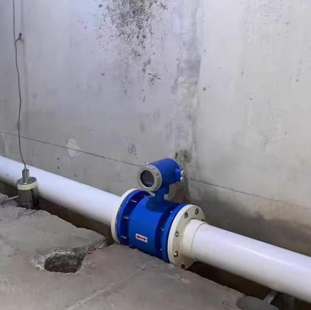
Grounding ring systems — standard on all properly specified mag meters for non-conductive pipe materials — provide the direct fluid-to-earth connection that prevents stray currents from flowing through the electrode circuit.
In a documented case from an automotive manufacturing facility in Germany, 14 standard mag meters installed near VFD-controlled conveyor motors showed flow reading errors of 6–12% within three months of commissioning. Replacing them with dual-frequency excitation units with dedicated earth bonding reduced average measurement error to 0.3% — well within the ±0.5% accuracy class specification.
الـ electromagnetic flow meter selection guide from Jade Ant Instruments covers liner and electrode specifications alongside EMI grounding requirements, which is the right framework for specifying any mag meter in an electrically noisy plant.
Best Applications and Industry Fit
| Industry | Typical Application | Recommended Size Range | EMI Risk Level |
|---|---|---|---|
| المعالجة الكيميائية | Acid/base dosing, solvent metering | DN15–DN100 | High (VFDs, welding) |
| المياه ومياه الصرف الصحي | Intake, distribution, sludge return | DN50–DN600 | Medium (pump VFDs) |
| المأكولات والمشروبات | CIP fluid monitoring, ingredient dosing | DN15–DN200 | Medium (automated lines) |
| Mining & Minerals | Slurry transport, reagent addition | DN50–DN300 | High (heavy motors) |
| Pharmaceutical | WFI distribution, buffer preparation | DN10–DN100 | Low–Medium |
Electromagnetic meters handle fluids with conductivity ≥ 5 µS/cm — covering virtually all aqueous process streams. They are not suitable for hydrocarbons, gases, or deionized water below the conductivity threshold.
Pricing, Availability, and Distributor Margins
Entry-level EMI-rated mag meters (standard accuracy ±0.5%, basic HART output) for DN50 pipe typically run USD 1,200–2,500 at the wholesale level. Advanced models with dual-frequency excitation, digital self-verification, and multi-protocol output (HART, PROFIBUS, Modbus) run USD 2,500–5,500 for the same pipe size.
The margin story for distributors is straightforward: the premium EMI-rated unit is rarely three times better than the standard unit — but the conversation with the end-user changes completely. When you can demonstrate that the additional USD 1,000–2,000 prevents measurement errors worth USD 30,000–80,000 per year in a batch chemical process, the price objection often disappears entirely.
Volume discount structures typically activate at 5, 10, and 25 units ordered simultaneously — worth negotiating when you have a retrofit project covering multiple measurement points in a single facility.
Common Customer Objections and How to Address Them
“Why is this more expensive than standard meters?” Show them the cost of the alternative. A 4% measurement error on a 500 m³/h water treatment line, running 24/7, means 175,200 m³ of unaccounted flow per year. At a chemical plant where that flow represents a reagent worth USD 0.50/L, the measurement error costs USD 87,600 annually. The USD 1,500 price premium for an EMI-hardened unit pays back in roughly 6 days.
“Do we really need this level of EMI protection?” Ask them to identify the nearest VFD or welding equipment to the measurement point. If the answer is “within 30 meters,” the answer is yes. If there are multiple VFDs on the same power distribution panel, the answer is an emphatic yes.
“What if we install it incorrectly?” Offer installation guidance as part of the specification package. The دليل أفضل ممارسات تركيب مقياس التدفق from Jade Ant Instruments outlines the grounding and cable routing requirements that prevent the majority of field EMI problems.

Proper grounding is the single most impactful installation step for EMI-resistant mag meter performance — and the most frequently skipped.
Flow Meter #2 — Vortex Flow Meter with Digital Signal Processing: The Budget-Conscious Choice
Why This Meter Offers Best Value for Cost-Sensitive Customers
The vortex flow meter — which measures the frequency of vortices shed by a bluff body (obstruction) placed in the flow stream — generates a digital, frequency-based output signal rather than a small analog voltage. This fundamental design difference gives vortex meters an inherent EMI advantage over electromagnetic meters in many noise environments: a frequency signal is far less susceptible to amplitude noise than a millivolt-level voltage signal.
In practice, a well-designed vortex meter with proper digital signal processing can operate reliably in moderate-EMI environments at a significant price advantage over premium EMI-hardened mag meters.
At a food processing facility in Thailand, eight standard vortex meters replaced turbine meters on clean water cooling lines running alongside VFD-controlled refrigeration compressors. At a unit price of USD 850 versus USD 2,100 for the EMI-hardened mag meters initially specified, the cost saving across eight measurement points was USD 10,000 — without any measurable accuracy compromise in the moderate-EMI environment. The key was the site assessment: a moderate-EMI facility, not a severe one, where vortex technology is the correct value-optimized choice.
Best Applications and Industry Fit
Vortex meters excel on clean liquids, gases, and steam where the fluid carries no significant solids and the flow velocity stays above the minimum measurable threshold (typically 0.5–1.5 m/s depending on the pipe size and fluid density). For steam measurement — saturated or superheated — vortex is often the first-choice technology, with no alternative that matches its combination of accuracy, pressure rating, and cost.
Where vortex meters underperform: at low flow velocities, on fluids with significant solids or fibrous content, and in severe radiated EMI environments at close range to high-power welding equipment. In those cases, the upgrade to an EMI-hardened mag meter is the correct recommendation.
| التطبيق | Performance in Moderate EMI | Performance in Severe EMI |
|---|---|---|
| Steam (saturated/superheated) | ممتاز | Good with shielded cable |
| Clean water & cooling lines | ممتاز | Adequate |
| Natural gas metering | ممتاز | Good |
| Chemical solvents (low-viscosity) | Good | Adequate |
| Slurries / viscous fluids | Not recommended | Not recommended |
Pricing, Availability, and Distributor Margins
Standard vortex meters for DN25–DN100 applications run USD 600–1,800 at the distributor level, making them one of the most margin-friendly technologies in the flow instrumentation catalog. Inventory turnover rates are strong because vortex meters cover steam, gas, and clean liquid applications that appear across virtually every industrial vertical.
At the product level, margins of 25–40% are achievable on vortex meters for distributors with established accounts, compared to 15–25% on premium electromagnetic meters where manufacturer pricing is more tightly controlled. For agents building toward a service-bundled revenue model, vortex meters represent a strong base product with multiple cross-sell opportunities (pressure transmitters, temperature sensors for multivariable measurement, insulation jackets for steam service).
Common Customer Objections and How to Address Them
“How does this compare to the premium EMI-hardened mag meter?” Frame the comparison around the actual EMI environment. In a moderate-noise facility — VFDs present but cable routing is manageable, welding is in a separate area — the vortex meter’s frequency output provides adequate EMI rejection at significantly lower cost. The premium mag meter is justified when the environment is severe. Document your site assessment so the recommendation is defensible.
“Will this meter fail in our high-EMI environment?” Be direct: if the assessment shows the facility exceeds 10 V/m average radiated field (common near welding lines or large VFD banks), the vortex meter is not the right choice. Show the client the data, explain the risk, and recommend the appropriate upgrade. That honesty protects your relationship.
“What’s the warranty and support?” Standard industry warranty is 12–24 months. Position your own technical support — site assessment capability, installation guidance, calibration scheduling — as the service layer that extends the effective value of the product beyond the warranty period.
Flow Meter #3 — Coriolis Mass Flow Meter: The Specialized Solution
Why This Meter Solves Specific Industry Challenges
The Coriolis flow meter — which directly measures mass flow rate by detecting the phase shift in vibrating flow tubes caused by the Coriolis effect — is the only flow meter technology that is inherently, structurally immune to the primary EMI interference mechanism. Because the measurement is based on mechanical vibration frequency and phase difference rather than electromagnetic induction or differential pressure, the primary sensing element is not susceptible to electromagnetic fields in the way that mag meters and vortex meters can be.
The transmitter electronics still require proper EMI protection — and quality Coriolis transmitters are designed with this in mind — but the fundamental measurement principle avoids the core vulnerability entirely.
In pharmaceutical manufacturing, Coriolis meters have become the default for high-value API ingredient dosing, clean steam measurement, and sterile fluid transfer monitoring. The combination of EMI immunity, mass flow measurement (no density correction required), and accuracy to ±0.1% makes them the specification of choice where both measurement precision and electrical noise immunity are simultaneously required.
Jade Ant Instruments’ guide to top Coriolis mass flow meters covers the technology selection criteria and key specifications in detail.
Best Applications and Industry Fit
Coriolis meters address the applications where no other technology can simultaneously deliver mass measurement accuracy and EMI immunity:
- High-value chemical dosing where a 0.5% mass measurement error means a 0.5% raw material loss directly to margin
- Pharmaceutical API metering where FDA 21 CFR Part 11 documentation requirements make the calibration stability of a Coriolis meter the only practical compliance path
- Custody transfer of high-value fluids — petrochemicals, specialty solvents — where billing accuracy at ±0.1% is contractually required
- Environments with extreme radiated EMI from multiple simultaneous heavy sources, where even premium mag meters show residual interference
The limitation is cost: a Coriolis meter in DN25 runs USD 3,500–8,000, versus USD 600–1,500 for a vortex or mag meter at the same size. This is the specialized solution for the applications that genuinely require it, not the default recommendation.
Pricing, Availability, and Distributor Margins
At USD 3,500–15,000 for typical industrial sizes, Coriolis meters represent the highest-revenue product in the flow instrumentation portfolio. Margins are compressed compared to vortex — 15–22% is typical at the distributor level — but the absolute profit per unit sold is significantly higher.
The sales cycle is longer because the specification and justification process is more involved. Build ROI case studies: a chemical company dosing USD 80/kg specialty reagent at 0.5% measurement error across 2,000 batches per year is absorbing USD 80,000+ in avoidable raw material cost annually. A USD 6,000 Coriolis meter that eliminates that error pays back in weeks.
Common Customer Objections and How to Address Them
“Is this overkill for our application?” Only one question matters: what is the cost of a 0.5% mass measurement error in your process? Calculate that number with the client in front of you. If the annual cost of imprecision exceeds the Coriolis premium by a factor of 2 or more, it’s not overkill — it’s the correct economic decision.
“Can we use a standard meter instead?” In some cases, yes. If the application is volume-based billing for water, or non-critical process monitoring, a well-grounded mag meter is the right call. Coriolis becomes non-negotiable when mass accuracy matters and the EMI environment rules out other options.
“What’s the learning curve for installation and maintenance?” Coriolis meters require no straight-run, no grounding rings, and no fluid conductivity. Installation is actually simpler than a mag meter in many respects. The transmitter configuration requires familiarity with density and temperature compensation parameters — a half-day of training is sufficient for a competent instrumentation technician.
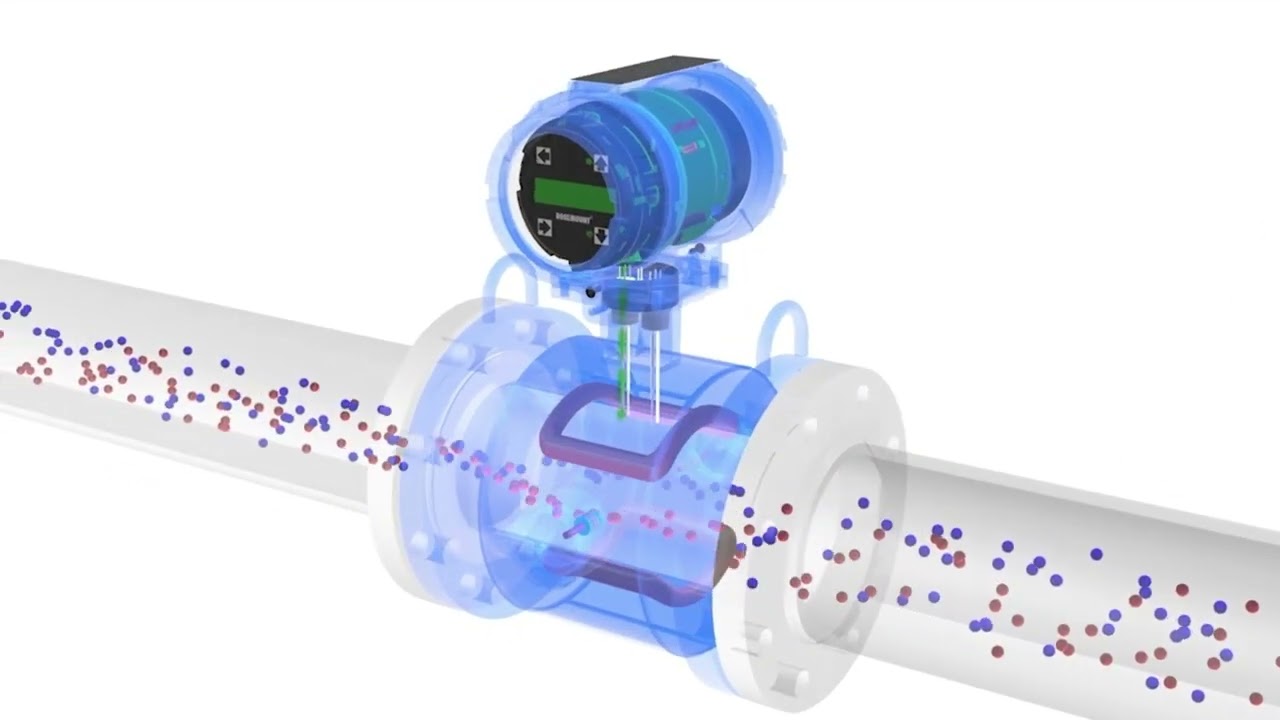
📹 Video: Introduction to Magnetic Flowmeter Technology — how the electromagnetic measurement principle interacts with electrical noise in industrial environments. Essential viewing for your technical team. Watch on YouTube →
Flow Meter #4 — Clamp-On Ultrasonic Flow Meter: The Technology Leader
Why This Meter Represents the Future of EMI Resistance
The clamp-on ultrasonic flow meter — which measures flow velocity by transmitting ultrasonic pulses through the pipe wall and detecting the transit-time difference between pulses traveling with and against the flow — offers a structural EMI advantage that no inline wetted meter can match: the transducers are mounted outside the pipe.
Because the signal path is acoustic (mechanical vibration at ultrasonic frequencies) rather than electrical, the measurement principle is immune to electromagnetic fields. The transducer electronics and transmitter require standard EMI protection, but the core measurement is inherently isolated from the electrical environment inside the facility.
This non-invasive approach also provides the installation flexibility that makes it the “technology leader” in situations where modifying the pipe is not possible or where process shutdown is prohibitively expensive. A clamp-on ultrasonic meter can be installed in 2–4 hours on any pipe material — carbon steel, stainless steel, HDPE, copper — without cutting, welding, or process shutdown.
For distributors serving clients in advanced manufacturing environments — data centers, semiconductor fabrication, pharmaceutical manufacturing, and facilities undergoing Industry 4.0 digital transformation — clamp-on ultrasonic meters represent the most rapidly growing product category. The global ultrasonic flow meter market is projected to grow at 5.9% CAGR through 2030, reaching USD 3.56 billion, with clamp-on technology capturing an increasing share of new installations.
Jade Ant Instruments’ clamp-on vs. transit-time non-invasive flow meter comparison is a useful reference for your team when clients ask about the technology options within ultrasonic metering.
Best Applications and Industry Fit
| التطبيق | Why Ultrasonic Clamp-On Leads | Typical Pipe Size | EMI Immunity Level |
|---|---|---|---|
| Data center cooling (chilled water) | No shutdown, non-invasive, IoT integration | DN50–DN300 | Inherent (acoustic signal) |
| District heating networks | Large-bore outdoor pipes, minimal retrofit disruption | DN100–DN600 | Inherent |
| Pharmaceutical utility (WFI, PW) | No wetted components, hygienic measurement | DN15–DN100 | Inherent |
| Petrochemical pipeline monitoring | Hazardous area, no process penetration | DN100–DN1200 | Inherent |
| Renewable energy (heat pumps) | Bidirectional flow, EN 1434 heat metering | DN25–DN200 | Inherent |
Limitations: ultrasonic clamp-on accuracy (typically ±1–2%) is lower than inline mag meters (±0.2–0.5%). For custody transfer and high-precision dosing applications, the inline alternatives are usually preferred. On fluids with significant suspended solids (>5% by volume) or gas bubbles, transit-time ultrasonic accuracy degrades — Doppler ultrasonic is the alternative for those fluids.
Pricing, Availability, and Distributor Margins
Portable clamp-on ultrasonic meters (handheld, battery-operated, used for site audits and temporary measurement) run USD 1,500–4,500 at the distributor level — a strong entry point for introducing the technology to clients without requiring a full installation commitment. Permanent fixed installations with digital outputs and cloud connectivity run USD 3,500–12,000 depending on pipe size and transmitter specification.
The business development opportunity here is multi-stage: sell a portable unit for a site audit, demonstrate performance, then convert to a permanent installation recommendation. This two-step sales model builds client confidence and gives you direct measurement data to justify the permanent installation investment.
Common Customer Objections and How to Address Them
“Isn’t this overcomplicated for our needs?” The installation is actually simpler than any inline meter — no process shutdown, no pipe cutting, no pressure testing. The “complexity” is in the transducer spacing calculation, which your team handles with the manufacturer’s sizing software. From the client’s perspective, the meter appears on the pipe without interrupting their operation.
“What if the technology becomes obsolete?” Ultrasonic flow measurement has been in industrial use since the 1970s and is the dominant technology in natural gas custody transfer (AGA-9), water supply (ISO 17089), and heat metering (EN 1434). It’s becoming more sophisticated, not less relevant.
“How does this integrate with our existing systems?” Modern permanent clamp-on meters output standard HART, Modbus RTU/TCP, or 4–20 mA signals, and the latest generation supports OPC-UA and direct cloud connectivity via Ethernet. Integration with existing DCS, SCADA, or BMS systems follows the same process as any digital field instrument.

Clamp-on ultrasonic meters mount externally on the pipe — eliminating wetted components, avoiding process shutdown, and providing inherent immunity to internal EMI from the fluid circuit.
Flow Meter #5 — Thermal Mass Flow Meter: The Reliable Standby
Why This Meter Earns Customer Trust Through Consistency
The thermal mass flow meter — which measures gas mass flow rate by monitoring the cooling effect of the flowing gas on a heated sensor element — occupies a specific and durable niche: direct mass flow measurement of gases without the cost and complexity of a Coriolis meter.
In compressed air systems, natural gas distribution, combustion air monitoring, and specialty gas applications, thermal mass meters have been the consistent, trusted choice for 25+ years. Their reliability comes from simplicity: no moving parts, no pressure drop (in inline insertion designs), and a direct mass flow output without requiring temperature or pressure compensation.
For EMI performance, modern thermal mass meters use differential temperature measurement between two matched sensors — a heated element and a reference element — with the mass flow derived from the differential signal. The measurement principle is relatively robust against EMI noise because the signal is a temperature difference (a slowly changing quantity) rather than a rapidly varying electrical signal. Properly shielded thermal meters perform adequately in moderate-EMI environments and, unlike mag meters, require no grounding rings or special fluid conductivity.
Best Applications and Industry Fit
Thermal mass meters are specifically designed for gas measurement. They do not measure liquids. The application focus is:
- Compressed air auditing and leak detection — thermal meters in DN15–DN50 sizes are the standard tool for quantifying compressed air consumption and identifying distribution losses (industry benchmark: 20–30% of compressed air produced is typically lost to leaks, representing significant energy cost in most manufacturing facilities)
- Natural gas submetering in industrial facilities where individual equipment consumption needs to be tracked
- Combustion air control on boilers, kilns, and industrial burners where air-to-fuel ratio optimization reduces energy cost
- Specialty gas monitoring in semiconductor manufacturing and laboratory environments
| التطبيق | Annual Cost Saving Potential | Thermal Meter Cost | Payback Period |
|---|---|---|---|
| Compressed air leak audit (large plant) | USD 30,000–80,000 | USD 1,500–3,500 | 2–6 weeks |
| Gas submetering (10 process points) | USD 15,000–40,000 (energy allocation) | USD 8,000–20,000 total | 3–8 months |
| Combustion air optimization | USD 20,000–60,000 | USD 2,000–5,000 | 2–4 months |
Pricing, Availability, and Distributor Margins
Thermal mass meters at DN15–DN50 run USD 800–3,500 depending on configuration, gas type, and communication output. Insertion-type probes for larger pipes (DN80–DN300+) run USD 1,500–6,000. Margins are typically 30–45% for distributors — stronger than electromagnetic and Coriolis because fewer distributors are active in the gas measurement niche relative to liquid flow instrumentation.
The cross-sell opportunity is significant: clients who are auditing compressed air systems also need pressure transmitters, flow control valves, and leak detection equipment. A thermal mass meter sale can anchor a much larger system supply package.
Common Customer Objections and How to Address Them
“Why choose this over newer models?” Thermal mass meters are designed for a specific application — direct gas mass flow — and they do it better and more cost-effectively than alternatives. Coriolis meters measure gas accurately but cost 5–10 times more for comparable pipe sizes. Differential pressure and vortex meters require pressure/temperature compensation to deliver mass flow. For gas-only applications, thermal is the most economical path to mass flow measurement.
“Is this meter becoming outdated?” The opposite is true. Compressed air energy efficiency and gas submetering are growing regulatory requirements under ISO 50001 energy management standards and under various national energy efficiency regulations. Demand for thermal mass meters in industrial applications is increasing, not declining.
“What happens when the manufacturer discontinues support?” Choose manufacturers with published spare parts availability commitments (typically 10 years minimum) and replacement-element stocking programs. Thermal meter sensors — the heated and reference elements — are the primary wear parts and should be available for the life of the installation.
Comparative Analysis: Making the Right Recommendation for Each Customer
Side-by-Side Performance Comparison Table
| المواصفات | EMI-Hardened Electromagnetic | Vortex (Digital Signal) | Coriolis Mass Flow | مشبك بالموجات فوق الصوتية | Thermal Mass Flow |
|---|---|---|---|---|---|
| مبدأ القياس | Faraday induction | Vortex shedding frequency | Coriolis effect | Transit-time acoustic | Heat dissipation |
| Fluid Type | Conductive liquids (≥5 µS/cm) | Clean liquids, gas, steam | Liquids, gases, slurries | Liquids (clean to moderate) | Gases only |
| الدقة النموذجية | ±0.2–0.51 TP3T | ±0.5–1.0% | ±0.1–0.15% | ±1.0–2.0% | ±1.0–2.0% |
| انخفاض الضغط | صفر | Moderate (bluff body) | High (in small sizes) | Zero (external mount) | Zero to low |
| EMI Resistance (moderate) | Excellent with grounding | Good (frequency signal) | Excellent (acoustic) | Excellent (acoustic) | Good |
| EMI Resistance (severe) | Good (dual-frequency) | Adequate | ممتاز | ممتاز | Adequate |
| Moving Parts | لا شيء | لا شيء | لا شيء | لا شيء | لا شيء |
| Typical Installed Cost (DN50) | 1,500–4,500 دولار أمريكي | 800–2,200 دولار أمريكي | USD 4,500–12,000 | USD 3,500–9,000 | USD 1,200–3,500 |
| Ideal EMI Environment | Moderate–Severe | منخفض – متوسط | All environments | All environments | منخفض – متوسط |
| 10-Year TCO (typical) | USD 8,000–14,000 | USD 6,000–10,000 | USD 14,000–25,000 | USD 9,000–18,000 | USD 5,000–9,000 |
| Best Industry Match | Chemical, water, food & bev | Steam, gas, clean liquids | Pharma, custody transfer | Retrofit, large-bore, non-invasive | Compressed air, gas sub-metering |
Decision-Making Framework for Your Sales Team
Walk through these five questions with every client inquiry involving an industrial EMI environment:
Question 1: What is the fluid? Liquid or gas? Conductive or non-conductive? Solids content? This eliminates incompatible technologies immediately — mag meters don’t work for non-conductive fluids; thermal meters are gas-only; vortex meters struggle with high-viscosity or high-solids fluids.
Question 2: What is the EMI environment? Identify the nearest VFD, welding station, or high-voltage cable to the measurement point. If it’s within 10 meters and operating continuously, specify for severe EMI. If it’s 30 meters away or intermittent, moderate-EMI rated meters will typically suffice.
Question 3: Is mass flow or volume flow required? If the client is billing by mass (chemical sales, gas supply, high-value liquid custody transfer), Coriolis or thermal mass is the correct category. If volume is sufficient, electromagnetic, vortex, or ultrasonic covers the application at lower cost.
Question 4: Can the pipe be modified? If no — shutdown is not permitted, welding on the pipe is not allowed, or the pipe material is unusual (e.g., lined or exotic alloy) — clamp-on ultrasonic is the appropriate technology regardless of other considerations.
Question 5: What is the accuracy requirement? For custody transfer (±0.1–0.2%), specify Coriolis or EMI-hardened mag meter with calibration certificate. For process monitoring (±0.5–1.0%), vortex or moderate-grade mag meter is appropriate. For indicative flow only (±1–2%), any technology including clamp-on ultrasonic meets the requirement.
Red flags indicating a customer needs premium EMI protection:
- Multiple VFD-controlled motors within 20 meters of the measurement point
- Welding operations in the same building section (not just the same facility)
- Previous meter at the same location showing erratic readings or zero drift
- High-frequency switching power supplies (UPS systems, inverter panels) in the same electrical panel as the meter
- Any cathodic protection system present on the pipeline
How to Communicate Technical Differences to Non-Technical Buyers
Not every client contact is an instrumentation engineer. Plant managers, procurement directors, and operations managers make or influence buying decisions — and they don’t think in terms of CMRR or dual-frequency excitation.
Translate specifications into business consequences:
- “This meter rejects electrical noise from your VFD drives” → “Your pump control system won’t interfere with flow measurement accuracy”
- “Differential signal processing at 120 dB CMRR” → “Even with welding 15 meters away, the meter reads within ±0.5%”
- “IEC 61326-1 Class 2 certified” → “This was tested to the standard that covers industrial environments like yours — not laboratory conditions”
The frame that works most reliably: “The standard meter costs X less upfront. If it reads 3% high in your facility — which it will, based on your EMI environment — your material cost error over 12 months is Y. The premium meter eliminates that error. The ROI is [Y minus X] in the first year.”
Quantify the measurement error cost in the client’s own production terms, and the technical conversation becomes a financial one that non-technical buyers understand immediately.
Installation, Integration, and Customer Support Considerations
Pre-Installation Assessment and Site Evaluation
Before recommending any flow meter for an industrial application with EMI concerns, your team should complete a basic site evaluation. This does not require specialized equipment — a structured observation checklist protects your recommendation and protects the client.
Site evaluation checklist for EMI risk assessment:
| Item to Check | Low Risk | Medium Risk | High Risk |
|---|---|---|---|
| VFD motors within 30 m of measurement point | لا شيء | 1–3, >10 m away | 3+, or any within 10 m |
| Welding operations in same building | None or separate building | Same building, separate area | Within 20 m of measurement point |
| High-voltage cables near signal cables | No crossing or parallel runs | Some crossing, separated | Parallel runs, shared conduit |
| Previous meter at same location | No issues reported | Occasional drift reported | Known interference problem |
| Cable routing infrastructure | Segregated signal/power trays | Mixed trays, some separation | Shared trays, no separation |
| Ground bonding at measurement point | Confirmed, <10 Ω | Unverified | No dedicated ground |
A site that scores Medium or High on three or more items should be specified with an EMI-hardened meter. Document the assessment. If the client later asks why you recommended the premium unit, the assessment record is your defensible answer.
For complex sites, the Engineering ToolBox flowmeter selection framework provides a useful reference for cross-checking technology selection against site conditions.
Installation Best Practices and Common Mistakes
The most preventable EMI problems in field installations trace to four recurring mistakes:
Mistake 1: Signal cables routed in the same tray as VFD output cables. The high-frequency switching noise on a VFD output cable radiates intensely to any parallel signal cable within 30 cm. The fix is simple — separate physical routing — but requires knowing about the problem before installation.
Mistake 2: Grounding rings omitted on non-metallic pipe. A mag meter installed on an HDPE or PVC pipe without grounding rings has no reference potential for the measurement signal. Stray currents flow through the electrodes instead, generating offsets of 5–20%. This is the most frequently diagnosed cause of mag meter complaints in field service records.
Mistake 3: Shield grounded at both ends. A cable shield grounded at both the transmitter and the field junction creates a conductive loop. Power-frequency magnetic fields induce a current in this loop — which flows through the shield and couples into the signal cable. Ground the shield at one end only (the transmitter end, unless the manufacturer’s documentation specifies otherwise).
Mistake 4: No minimum straight-run. Installing a meter immediately downstream of a partially open control valve, pump outlet, or 90° elbow creates flow turbulence that generates measurement errors independent of EMI. Even in a clean electrical environment, turbulence-induced errors of 2–8% are common in poorly planned installations.
For your most critical accounts, offer a pre-installation site visit as a paid service. Charge USD 300–600 for a half-day assessment and installation review. This is a direct margin contribution and an investment in preventing the service calls and warranty discussions that follow from poorly planned installations.
Post-Installation Validation and Performance Verification
Once the meter is installed, a structured validation procedure confirms that the EMI mitigation measures are working and establishes baseline performance data for future reference.
Commissioning validation sequence:
- Zero-flow verification: isolate the meter at zero flow and confirm the reading is within the manufacturer’s specified zero-flow cutoff. Any non-zero reading at proven zero flow indicates a grounding or interference problem.
- High-flow point check: if a reference measurement is available (a nearby portable clamp-on ultrasonic, or a temporary weir/flume), compare readings across the full flow range and document deviations.
- EMI stress test: operate the nearest VFD-controlled equipment and observe whether the flow reading changes. A stable reading during VFD operation confirms the EMI mitigation is effective. A fluctuating reading identifies a remaining issue before the client signs off on commissioning.
- Document all results: record the as-found readings, installation parameters (grounding resistance, cable routing description), and any deviations observed. This documentation protects you if the client later reports accuracy problems.
Training Your Sales and Technical Teams
Your team’s credibility in EMI-related conversations is a direct function of how confidently they can answer the three questions clients ask most often: Is my facility actually a problem environment? Which meter handles my situation? And what do I need to do differently in installation?
Build a half-day internal training module covering: EMI source identification (VFDs, welding, high-voltage distribution), IEC 61326-1 Class 1 vs. Class 2 and what the difference means in practice, the five meter technologies and their inherent EMI characteristics, grounding requirements for mag meters on metallic and non-metallic pipe, and the site assessment checklist. Run the module quarterly, updating the case studies with examples from your own territory.
الـ 8 flow meter distributor mistakes guide from Jade Ant Instruments covers the broader selection competency framework your team should build on — EMI resistance is one chapter in a larger story about technical advisory capability.
Industry-Specific Applications and Success Stories
Manufacturing and Heavy Industry
Heavy manufacturing — automotive assembly, steel production, chemical synthesis — combines the highest EMI loads with some of the highest measurement accuracy requirements.
An automotive parts manufacturer in South Korea installed 22 electromagnetic flow meters on cooling water circuits for CNC machining centers. The initial specification used standard mag meters. Within four months, 11 of the 22 meters showed persistent ±4–7% accuracy deviation during production shifts, correlated with VFD activity on the machining center servo motors. All 22 meters were replaced with dual-frequency excitation units, cable routing was modified to maintain 500 mm separation from servo motor cables, and dedicated earth bonds were installed at each measurement point. Post-retrofit accuracy testing showed all 22 meters within ±0.4% across full production cycles.
The cost: USD 38,000 for the retrofit (replacement meters, labor, cable rerouting). The avoided annual cost of the 5% average measurement error on cooling water chemistry dosing: USD 62,000. Net payback: 7.4 months.
For high-EMI manufacturing environments, the leading flow meter manufacturers comparison provides a side-by-side technical review of the brands most frequently specified in automotive and steel applications.
تصنيع الأغذية والمشروبات
Food and beverage facilities present a combination of EMI challenges (automated bottling lines with multiple VFD-controlled motors, automated CIP systems with large pumps) and strict hygiene requirements that limit meter design options.
The primary technology for conductive liquids in hygienic applications is the electromagnetic meter with a PFA or hard rubber liner, Hastelloy or titanium electrodes, and hygienic flanges (DIN 11851, SMS, or Tri-Clamp connections). In food facilities, the EMI environment is typically moderate rather than severe — VFDs are present but welding is confined to maintenance periods — which means properly grounded mag meters with standard dual-frequency excitation perform reliably without requiring the full premium EMI specification.
Where food facilities show the most significant EMI sensitivity is in inline CIP (clean-in-place) monitoring, where flow switches and flow meters on the return line must accurately detect the transition between product and cleaning solution. Signal instability during CIP — often attributed to EMI from the high-flow CIP pump VFD — has been eliminated in multiple facilities by moving from single-frequency to dual-frequency excitation and ensuring signal cable separation from the CIP pump starter panel.
Pharmaceutical and Life Sciences
Pharmaceutical manufacturing imposes the strictest documentation requirements of any industry on flow instrumentation. Every measurement point on a validated process line requires a defined calibration schedule, full traceability, and documented IQ/OQ/PQ records (Installation, Operational, and Performance Qualification).
For EMI performance in pharmaceutical environments, the primary concern is not measurement accuracy per se — pharmaceutical facilities are typically moderate-EMI environments — but calibration stability over time. A meter that shows EMI-induced drift between calibration intervals creates a documentation crisis during regulatory inspection.
Clamp-on ultrasonic meters are the preferred technology for Water for Injection (WFI) and Purified Water distribution because they add no wetted components to hygienic piping and require no process modification to install. Coriolis meters are preferred for mass-critical ingredient dosing. Both technologies’ inherent EMI immunity through acoustic measurement provides the calibration stability that pharmaceutical qualification protocols require.
معالجة المياه ومياه الصرف الصحي
Water utilities present a unique EMI challenge: meters are often installed outdoors, near high-voltage power infrastructure, and in pump stations where large VFD-controlled pumps generate significant electrical noise in confined spaces.
The standard solution for pump stations is a premium-grade mag meter with polyurethane or hard rubber liner (wastewater), 316L electrodes, and dedicated earth bonding to the station’s ground grid. Signal cables should be run in metallic conduit, bonded to the ground grid at both ends of the conduit run. This combination reliably delivers ±0.5% performance in the presence of large pump VFDs.
For large-diameter transmission mains (DN400+), clamp-on ultrasonic is increasingly the preferred option because installation on in-service mains avoids costly service interruptions. ISO 17089 governs ultrasonic measurement of liquid flow in closed conduits and provides the accuracy framework for utility-grade installations.
Water utility accounts often involve large recurring orders — multiple pump stations, distributed measurement network upgrades — that make them high-value long-term accounts worth the investment of detailed EMI site assessment and specification support.
Pricing Strategy and Margin Optimization for Distributors
Understanding Wholesale Pricing and Volume Incentives
Flow meter pricing at the distributor level follows a tiered structure that rewards volume and relationship commitment. For the five technologies discussed in this guide, typical wholesale price structures work as follows:
| التكنولوجيا | 1–5 Units | 6–20 Units | 21–50 Units | 50+ Units |
|---|---|---|---|---|
| EMI-Hardened Electromagnetic (DN50) | List −25% | List −32% | List −38% | List −42%+ |
| Vortex (DN50) | List −22% | List −28% | List −34% | List −38%+ |
| Coriolis (DN25) | List −18% | List −22% | List −28% | Negotiate |
| Clamp-On Ultrasonic (permanent) | List −20% | List −26% | List −32% | List −36%+ |
| Thermal Mass (DN50) | List −25% | List −30% | List −36% | List −40%+ |
Negotiate framework agreements with your primary manufacturer for annual volume commitments — even if purchasing is spread across individual orders throughout the year. A USD 500,000 annual commitment in electromagnetic meters typically unlocks 35–42% discount from list, compared to 25% for spot purchasing.
Bundling and Cross-Selling Opportunities
Every EMI-resistant flow meter sale is an anchor for a broader system supply package. The most consistently successful bundles:
- Electromagnetic meter + grounding rings + shielded signal cable + installation guide: Increases average order value by USD 200–600 and directly reduces the probability of installation-related complaints.
- Vortex meter + pressure transmitter + temperature transmitter for multivariable steam measurement: The combined package delivers a complete BTU/energy metering point. Average bundle value: USD 3,500–6,500 vs. USD 900–1,800 for the meter alone.
- Clamp-on ultrasonic + portable audit kit for site assessment: Positions the sale as a service engagement rather than a product purchase. The portable unit generates data that justifies the permanent installation.
- Thermal mass meter + compressed air audit report: Quantifies the energy saving potential, justifies the meter purchase with ROI data, and creates a maintenance services follow-on.
Positioning Premium Solutions Without Losing Price-Sensitive Customers
The key to protecting margins on EMI-resistant meters while keeping cost-conscious accounts is segmentation: match the technology to the actual EMI severity, not to the highest-specification option available.
A pharmaceutical utility monitoring cooling tower flow in a low-EMI environment doesn’t need a dual-frequency, Class 2 electromagnetic meter. A standard vortex with shielded cable is adequate, costs 40% less, and is the correct recommendation. The honesty of this recommendation builds trust — and when that same client later specifies a new batch reaction monitoring system in a high-VFD environment, they’ll come back to you for the premium meter because your previous recommendation proved accurate.
Margin erosion from aggressive competitors typically happens when a distributor has no technical differentiation. When your recommendation is backed by a site assessment, a documented EMI risk evaluation, and an ROI calculation, pricing becomes a secondary consideration. Clients who understand why they need what you’re recommending rarely leave for a 5% price difference.
Common Pitfalls Distributors Should Avoid
Recommending Meters Based on Price Alone
The flow meter industry has no shortage of low-cost products that meet minimum specification requirements in laboratory conditions. Distributing them into industrial EMI environments without proper selection support is a guaranteed path to warranty claims, client dissatisfaction, and eventual account loss.
The distributor who recommends by price alone wins the first order. The distributor who recommends correctly — sometimes at a higher cost, with a clear explanation of why — wins the account for years.
Underestimating EMI Challenges in Customer Facilities
EMI problems in industrial facilities are rarely visible before installation. Clients don’t typically volunteer that they have twelve VFD-controlled motors in the same building. Your site assessment process needs to be structured to surface this information proactively — through the checklist questions, not through optimistic assumptions about facility conditions.
Protect your recommendation with documented site assessment data. If the client later claims the meter is performing below specification, your site assessment record either supports your recommendation or identifies the gap between what was disclosed and what was found.
Neglecting Installation and Support
A correctly specified meter installed incorrectly produces incorrect measurements. Your commercial responsibility doesn’t end when the meter ships — it extends through commissioning. Offering installation review services (even at a modest charge) as a standard part of any industrial EMI-rated meter supply protects both the meter’s performance and your client relationship.
Failing to Educate Customers About EMI Risks
Most end-users don’t think about EMI until a measurement problem forces the conversation. Creating educational content — a one-page EMI risk assessment guide, a simple checklist for site survey — positions you as the expert who anticipates problems rather than the distributor who responds to complaints. Share this content proactively with every industrial account, not just those who’ve raised EMI concerns.
Future Trends in EMI-Resistant Flow Meter Technology
Industry 4.0 Integration and Smart Monitoring
Modern EMI-resistant flow meters increasingly include self-diagnostic capabilities that continuously monitor measurement quality, detect interference events, and report both flow data and instrument health through digital protocols. Endress+Hauser’s Heartbeat Technology, KROHNE’s IOMC diagnostics, and similar systems from other manufacturers generate verification reports without process interruption — a capability that reduces calibration costs and provides continuous quality assurance between scheduled calibration intervals.
As industrial facilities expand their IoT infrastructure, the ability of flow meters to report interference events — not just flow measurements — becomes a valuable diagnostic tool for the plant’s overall electrical health monitoring system. The global intelligent flow meter market is projected to reach USD 5.5 billion by 2035, growing at 4.9% CAGR (Market.us, 2025), driven largely by this demand for instruments that communicate their own operating status.
For distributors, this trend creates a recurring service opportunity: smart meters that generate diagnostic data create structured conversations about data interpretation, anomaly investigation, and preventive maintenance — all billable advisory services.
Advanced Materials and Shielding Innovation
The next generation of EMI shielding in flow instrumentation is moving beyond aluminum and steel enclosures toward multi-layer composite shielding that achieves 80 dB or higher effectiveness at lower weight and cost. Conductive polymer coatings — applied to enclosure interiors during manufacturing — supplement metallic enclosures by filling microscopic gaps that reduce conventional shielding effectiveness.
Ferrite absorbers integrated into cable glands and conduit fittings are also becoming standard on premium EMI-rated transmitters, absorbing high-frequency conducted EMI at the point of entry before it reaches the signal electronics. These material improvements are reducing the cost differential between standard and EMI-hardened meters, making premium EMI protection increasingly accessible across mid-range product categories.
Regulatory Changes and Compliance Requirements
IEC 61326-1 is currently under revision to address EMI environments generated by 5G wireless systems, which operate in frequency bands not covered by the previous standard generation. The updated standard, when published, will raise immunity requirements for industrial measurement equipment in high-density wireless environments — a direct consequence of the rapid deployment of 5G industrial private networks and wireless IoT infrastructure in manufacturing facilities.
For distributors, this regulatory evolution creates both a compliance urgency (facilities will need to verify that installed meters meet the updated standard) and a sales opportunity (meters purchased in the next 12–24 months should be specified against the forthcoming standard requirements to avoid premature replacement). Stay informed through IEC’s standard update tracking and brief your key accounts proactively when the updated standard publishes.
Building Your Expertise and Customer Confidence
Developing Your Team’s Technical Knowledge
Technical credibility is built through consistent preparation, not through product knowledge alone. The sales representative who can walk into a client’s facility, identify the three nearest EMI sources, explain which of those sources creates the most significant measurement risk, and recommend a specific meter with a specific installation configuration is demonstrating expertise that no catalog or price list can replicate.
Build that capability with a structured learning program: quarterly product knowledge sessions, annual hands-on training with each major meter technology, and a library of case studies organized by industry and EMI challenge type. The analog vs. digital flow meter comparison from Jade Ant Instruments provides a useful foundation for understanding how output technology choices interact with EMI performance.
Creating Case Studies from Your Customer Base
Every successful EMI-resistant installation in your territory is a case study waiting to be documented. A one-page summary — application description, EMI challenge identified, meter specified, installation measures implemented, measured outcome — becomes a powerful sales tool for similar applications at other facilities.
Clients in the same industry routinely face the same EMI challenges. A food and beverage client who solved a VFD interference problem on their bottling line becomes a reference for your next food and beverage prospect facing the same situation. Build the library systematically, and it compounds in value over time.
Positioning Yourself as the EMI Expert in Your Market
The EMI niche is genuinely underserved in flow instrumentation distribution. Most distributors treat EMI as a technical footnote rather than a primary selection criterion. An agent who actively develops and communicates EMI expertise — through educational content, site assessment services, and documented case studies — occupies a competitive position that is difficult and time-consuming for competitors to replicate.
Offer EMI site assessments as a standalone service. Publish brief technical guides (EMI risk assessment checklist, grounding requirements by technology) for your industrial client base. Present at local instrumentation or manufacturing industry association meetings. Over 18–24 months, these activities compound into a market reputation that attracts exactly the high-value industrial accounts where EMI-resistant meter margins are strongest.
Your Competitive Advantage in a Crowded Market
Why EMI Resistance Expertise Sets You Apart
The global flow meter market is growing toward USD 14.1 billion by 2035. In the industrial segment — manufacturing, chemical processing, oil and gas, water infrastructure — EMI is the norm, not the exception. Every facility running VFD-controlled motors, welding equipment, or expanding wireless infrastructure is a potential EMI problem waiting to become a measurement accuracy complaint.
Distributors and agents who understand this, who can assess the risk before the sale, specify the correct solution, guide the installation, and document the outcome, are offering something genuinely valuable. Not a product. A solution. And solutions command margin that products never can.
The five technologies reviewed in this guide — EMI-hardened electromagnetic, vortex, Coriolis, clamp-on ultrasonic, and thermal mass — cover the full spectrum of industrial liquid and gas measurement applications. Matching the right technology to the right environment, supported by site assessment data and documented performance expectations, is the service that turns a transactional account into a long-term partnership.
Start by auditing your current product portfolio for EMI rating documentation. For every electromagnetic and vortex meter you currently stock, confirm the IEC 61326-1 class rating. If you don’t have that information from your current manufacturers, request it — and if they can’t provide it, that’s a selection issue to address before the next industrial account order.
Next, build your site assessment capability: develop or adopt the EMI risk checklist, train your team on the five-question decision framework, and schedule one internal training session focused specifically on grounding requirements by technology type.
Then identify your top five industrial accounts and schedule a technical conversation — not a sales call — specifically about their EMI environment and current meter performance. What you learn from those conversations will shape your product mix and your service development priorities for the next 12 months.
Ready to position yourself as the EMI expert your industrial clients need?
الـ Jade Ant Instruments technical team works exclusively with distributors and agents to:
- Assess your current product portfolio against your clients’ EMI requirements
- Develop application-specific product configurations for your most demanding industrial accounts
- Provide technical training resources for your sales and installation teams
- Support your client-facing case study and educational content development
Explore the full electromagnetic, vortex, and turbine flow meter range at jadeantinstruments.com, or contact the distributor support team directly to discuss your territory’s specific EMI application challenges.

Technical expertise in EMI-resistant flow meter selection is the differentiator that converts price-comparison conversations into long-term advisory relationships.
Frequently Asked Questions for Distributors and Their Customers
Q1: What’s the difference between EMI shielding effectiveness ratings, and which ones matter most for industrial flow meters?
Shielding effectiveness is measured in decibels (dB) across a defined frequency range. For industrial flow meters, the critical range is 10 kHz to 1 GHz — the band covering VFD switching frequencies, radio communications, and cellular networks simultaneously. A rating of 60 dB means the enclosure reduces the external EMI field by a factor of 1,000 before it reaches the internal electronics. For facilities with active VFD equipment or welding operations, 60 dB minimum is the practical threshold. Below 40 dB, standard catalog meters may perform adequately in low-EMI environments but will exhibit measurement drift in moderate-to-high interference conditions. When reviewing manufacturer specifications, ask specifically for the rated dB value at 10 MHz and 1 GHz — those two data points reveal where real-world performance gaps typically occur.
Q2: Can a standard flow meter handle moderate EMI, or do we always need a specialized solution?
Standard meters work reliably in genuinely low-EMI environments — office buildings, clean rooms, laboratory settings, and facilities with no VFD-controlled motors within 50 meters of the measurement point. In manufacturing facilities with active VFD control systems, the answer changes: standard meters will typically show measurement drift of 3–8% when VFDs operate near the measurement point. The assessment question is whether “moderate EMI” in your client’s facility actually corresponds to what instrument manufacturers classify as moderate. A basic site survey using the checklist framework in this guide resolves the ambiguity before the order is placed, not after the meter is installed.
Q3: How does proper grounding eliminate EMI problems, and what happens if the client skips this step?
Ground loops and inadequate bonding are documented as the primary cause of measurement errors in EMI-sensitive environments, appearing in 50% of field service tickets for electromagnetic flow meters specifically. Without proper grounding, stray currents from VFDs, cathodic protection systems, and static buildup in plastic-lined pipes find the path of least resistance through the meter’s electrode circuit — the same path the measurement signal uses. The result is a current component that appears as a flow reading offset. A 4 mm² copper earth bond from the meter body to the plant’s main earth bus, installed at less than 10 Ω impedance, eliminates this pathway. Grounding rings on both flanges are mandatory on non-metallic pipe installations. Skipping either step in a moderate-to-high EMI environment reliably produces the “meter reads high” complaint within the first production cycle.
Q4: What’s the difference between shielded and unshielded cables for flow meter signal connections?
An unshielded cable acts as an antenna for EMI — it picks up radiated interference along its entire length and delivers it directly to the meter’s signal input. In a VFD-heavy environment, the noise level on an unshielded cable can easily exceed the measurement signal level for a standard electromagnetic flow meter (which operates at millivolt signal amplitudes). A shielded cable — with a conductive braid or foil surrounding the signal conductors and connected to earth at the transmitter end — provides 20–40 dB of radiated noise rejection, reducing interference to levels that the meter’s differential signal processing can manage. For any industrial application near VFD equipment, shielded cable is not optional — it’s the baseline installation requirement. Specify it explicitly in every purchase order that includes a meter for an industrial EMI environment.
Q5: Are there specific certifications your clients’ regulated industries must require from flow meter manufacturers?
Yes, and the requirements vary by industry. CE marking with explicit IEC 61326-1 Class 2 (industrial environment) compliance is the baseline for general industrial applications across Europe and most international markets. IEC 61000-4-3 radiated immunity at 10 V/m is the specific test that validates performance in VFD-heavy environments — ask manufacturers to confirm this specific test level rather than just “CE certified.” For pharmaceutical applications, 21 CFR Part 11 compliance governs electronic records and requires audit trail capability in the meter’s data logging functions. For food and beverage, NSF/ANSI 61 or EHEDG certification governs hygiene compliance. For custody transfer applications in oil and gas, API MPMS Chapter 5 or AGA-9 (for gas) sets the accuracy and traceability requirements. When your client is in a regulated industry, document the specific certifications required and confirm the meter’s compliance before the purchase order is issued.
Q6: How do variable frequency drives specifically affect flow meter accuracy, and what is the complete solution?
VFDs generate two distinct types of interference that affect flow meters. Conducted EMI travels through the power supply cables: the high-frequency switching transients generated by the VFD’s IGBT switching (at 2–16 kHz repetition) propagate along the AC power distribution system and can couple into the meter’s power supply if it shares the same distribution transformer. Radiated EMI is broadcast from the VFD, its output cables to the motor, and the motor itself as an antenna — and at close range to the measurement point, can reach field strengths exceeding 10 V/m. The complete solution requires three elements working together: an EMI-hardened meter with Class 2 immunity certification, shielded signal cable with proper single-point grounding, and physical separation of signal cables from VFD output cables (minimum 300 mm, no parallel routing). The SCADAmetrics EMI filter analysis provides additional technical detail on filtering approaches for VFD-induced interference in metering applications.
Q7: What’s the typical cost difference between EMI-resistant and standard flow meters, and how should distributors justify it?
At the DN50 size range most commonly discussed for industrial applications, EMI-hardened electromagnetic meters typically cost 15–40% more than standard catalog equivalents — roughly USD 800–1,500 additional on a mid-range model. The justification framework is straightforward: calculate the annual cost of the measurement error the standard meter will exhibit in the client’s specific EMI environment. For a chemical facility with 4% average error on a reagent stream worth USD 0.60/L at 200 L/min flow rate, the annual measurement error cost is USD 60,000 to 115,000. The USD 1,200 premium for the EMI-hardened unit returns within the first 10 days of operation. Present this calculation with the client’s actual production data, not with hypothetical numbers, and the price objection resolves itself.
Q8: Can retrofitting EMI protection to existing flow meters provide adequate performance, or is meter replacement the only reliable solution?
Retrofit options exist — external EMI filters on signal cables, ferrite cores on cable entries, additional earth bonding — and in mild EMI environments, they may reduce interference to acceptable levels. However, retrofitting cannot replicate the integrated EMI design of a purpose-built EMI-resistant meter. The dual-frequency excitation circuitry, the internal differential signal processing, and the precision-shielded sensor housing are engineering decisions made during the meter’s design phase. Adding an external filter after the fact addresses conducted interference on cables but does nothing for radiated interference that reaches the sensor electronics directly. For clients experiencing significant measurement error due to EMI, replacement with a properly rated unit is the reliable solution. Retrofitting is appropriate as a short-term interim measure while replacement is being planned and budgeted.
Q9: How often should EMI-resistant flow meters be recalibrated or serviced, and does EMI affect calibration stability?
Calibration intervals for EMI-resistant flow meters follow the same general industrial standards as other technology: annually for custody transfer and regulatory compliance applications, every 2–3 years for process monitoring applications where measurement accuracy tolerance is wider. EMI itself does not cause calibration drift in a properly functioning, correctly installed EMI-resistant meter — the shielding and filtering prevent interference from reaching the measurement circuit. However, degraded grounding connections (due to corrosion, vibration, or loose connections) can reduce EMI protection over time, allowing interference to gradually affect measurement accuracy between calibration intervals. Include a grounding continuity check (earth impedance < 10 Ω at the meter body) as part of every annual inspection, regardless of the nominal calibration interval.
Q10: What’s the practical difference between active and passive EMI filtering in flow meters, and which approach performs better in heavy industrial environments?
Passive EMI filtering uses physical shielding (Faraday cages, conductive enclosures) and passive electrical components (ferrite absorbers, capacitors, chokes) to block or absorb interference without requiring power or active processing. Passive filtering is reliable, requires no maintenance, and is effective across a broad frequency range — it’s the baseline approach in all quality industrial flow meters. Active EMI filtering uses electronic circuits (adaptive filters, digital signal processing, active noise cancellation) to identify and subtract interference from the measurement signal in real time. Active filtering extends protection to frequency ranges and interference levels where passive methods alone are insufficient, and is the approach used in dual-frequency excitation electromagnetic meters and advanced digital signal processing in ultrasonic transmitters. For heavy industrial environments — welding areas, VFD banks, high-voltage equipment in close proximity — active filtering is the differentiating feature of premium EMI-resistant meters and is worth specifying despite the additional cost.
Q11: How do I determine whether my client’s measurement problem is actually EMI, or something else entirely?
EMI-induced measurement problems have a characteristic signature: the error correlates with the operation of specific equipment, is intermittent or cyclical rather than constant, and often shows up as rapid signal fluctuation rather than a stable offset. Ask your client: does the reading fluctuate at specific times of day, or when specific equipment starts? Does it track the duty cycle of a VFD-controlled pump? Does it settle when the production line is stopped for maintenance? Affirmative answers to these questions strongly indicate EMI as the cause. Constant, stable offsets are more likely to indicate zero drift, grounding problems at steady state, or installation issues (partially full pipe, insufficient straight run). The wrong flow meter selection case study from Jade Ant Instruments walks through a documented diagnosis process that your team can use as a framework.
Q12: Are wireless flow meters appropriate for high-EMI environments, and what’s the guidance for facilities expanding their IoT infrastructure?
Wireless flow meters add complexity in high-EMI environments because the wireless communication system itself operates in the same electromagnetic spectrum that industrial EMI sources disrupt. A wireless meter in a VFD-heavy environment may experience both measurement interference (from the VFD’s effect on the meter’s signal circuit) and communication interference (from the VFD’s RF emissions disrupting the wireless data link). For the vast majority of high-EMI industrial applications, wired EMI-resistant meters remain the more reliable choice. The practical guidance for facilities expanding IoT infrastructure: deploy wired EMI-resistant meters for measurement accuracy, and use gateway devices with wired connections to the meters to provide wireless connectivity at the network layer rather than at the instrument layer. This architecture delivers both IoT connectivity and measurement reliability without compromising either.
Glossary of Key Technical Terms
EMI (Electromagnetic Interference): Unwanted electrical noise generated by external electromagnetic fields that disrupts the performance of electronic instruments. In industrial settings, primary sources include VFDs, welding equipment, high-voltage distribution systems, and wireless communications infrastructure.
Faraday Cage: A continuous conductive enclosure (typically aluminum or stainless steel) surrounding electronic components that absorbs and redirects electromagnetic fields, preventing them from reaching internal circuits. The effectiveness depends on the continuity of the conductive enclosure — any gap reduces shielding performance.
IEC 61326-1: The international standard specifying EMC (electromagnetic compatibility) requirements for electrical equipment used in measurement, control, and laboratory applications. Class 1 covers portable and non-industrial equipment (3 V/m radiated immunity); Class 2 covers permanently installed industrial equipment (10 V/m radiated immunity).
Dual-Frequency Excitation: An electromagnetic flow meter design technique that alternates the coil excitation between two AC frequencies (e.g., 6.25 Hz and 25 Hz). A genuine flow signal appears consistently at both frequencies; EMI-induced noise appears at only one, allowing the transmitter to identify and reject the interference.
CMRR (Common-Mode Rejection Ratio): Measured in dB, this describes a differential amplifier’s ability to reject noise that appears equally on both signal wires while amplifying the difference signal (the real measurement). A CMRR of 80 dB means the amplifier rejects common-mode noise by a factor of 10,000:1 relative to the differential signal.
Ground Loop: An unintended electrical circuit created when a cable shield or signal wire is connected to earth at more than one point, creating a conductive loop. Power-frequency magnetic fields induce currents in this loop, which flow through the signal cable and appear as measurement interference. Prevented by connecting cable shields to earth at one end only.
VFD (Variable Frequency Drive): An electronic controller that adjusts AC motor speed by varying the frequency of the power supply. VFDs use high-frequency switching (2–16 kHz) that generates significant conducted and radiated EMI — the most common source of flow meter measurement interference in manufacturing facilities.
Transit-Time Ultrasonic: A flow measurement principle that measures the difference in travel time of ultrasonic pulses sent with and against the flow direction. The time difference is proportional to flow velocity. Because the measurement signal is acoustic (mechanical) rather than electrical, the primary sensing mechanism is inherently immune to electromagnetic interference.
Coriolis Effect: The apparent deflection of a moving mass in a rotating reference frame. In Coriolis flow meters, the vibrating tubes create a rotating reference frame; flowing mass deflects the tube proportionally to mass flow rate. The measurement is detected as a phase shift between sensors on the tube — a mechanical measurement immune to electromagnetic fields.
Data references: IEC 61326-1:2021 (EMC standard for measurement equipment); IEC 61000-4-3 (Radiated immunity testing); Engineering ToolBox — Flowmeter Selection; Market.us Intelligent Flow Meter Market 2025; SCADAmetrics VFD EMI Filter Analysis; Jade Ant Instruments distributor technical resources.