Skid-Mounted Flow Meter Selection: An OEM Integration Guide
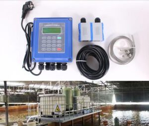
Image: Jade Ant Instruments product photo.
Quick answer: On a skid, the right flow meter is the one that fits the pipe layout, talks to the PLC on day one, and keeps its accuracy without a shutdown. The most accurate meter on paper often loses on all three. This guide shows how to pick by system fit first, then by specification.
I. The Strategic Role of Flow Measurement in Skid Integration
A skid is a small plant on a steel frame. Every pipe, valve, and instrument has to fit in a space your customer already decided. The flow meter is often the part that does not fit, or fits but causes problems six months later.
The high stakes of OEM integration: balancing performance with spatial constraints
A meter that needs 20 pipe diameters of straight run on a DN50 line asks for 1 metre of pipe. On a compact skid, that metre may not exist. So the layout gets bent, and the meter ends up next to an elbow where it reads wrong.
The price of that choice shows up later. Jade Ant Instruments’ skid-mount magmeter guide describes a water-treatment dosing skid builder that moved from turbine to electromagnetic meters. Field service calls about measurement accuracy fell by 40% over the next 24 months. The turbine bearings had been losing roughly 0.3% accuracy per month, which is too slow to notice in a weekly check and large enough to ruin a dosing batch.
Common pain points: installation bottlenecks, calibration drift, and compatibility issues
Skid builders tell us the same three stories:
- Installation bottlenecks. Flanges, fit-up, leak tests, and torque checks eat hours. Each meter adds two flanged joints.
- Calibration drift. The meter was right at the factory acceptance test. A year later, the customer’s quality team sees a 3% gap.
- Compatibility issues. The meter outputs 1,200 Hz pulses and the PLC input stops counting at 1,000 Hz. Totals read low. Nobody notices until a yield report.
Objective: from “component selection” to “system optimization”
Component selection means picking the meter with the best datasheet. System optimization means picking the meter that makes the whole skid smaller, faster to build, and easier to service. This guide gives you a step-by-step way to do the second one.
II. Defining System Requirements: The Pre-Selection Checklist
Before you compare brands, answer three questions. They remove half the options before you open a catalogue. Jade Ant’s flow meter selection guide and its five-factor framework use the same logic.
Fluid chemistry and process conditions: viscosity, conductivity, and temperature
Start with the fluid, not the meter.
Conductivity is how well a liquid carries electric current. A magnetic meter needs at least about 5 µS/cm. Deionized water, oils, and gases fall below that, so a magnetic meter will not read them.
Viscosity is how thick a liquid is. Honey is thick and water is thin. Jade Ant’s vortex meter documentation notes that vortex performance degrades above roughly 5 cP, and recommends magnetic or positive displacement designs for fluids above 20 cP.
Temperature limits the liner, seals, and electronics. Jade Ant’s intelligent electromagnetic flow meter is specified for −20 to +60 °C in the compact version and −20 to +160 °C with a remote transmitter. So a hot line may force you to split the sensor from the electronics, which changes your layout.
| Fluid property | Question to ask | What it rules out |
|---|---|---|
| Conductivity | Is it at least 5 µS/cm? | Magnetic meters on oils, gases, DI water |
| Viscosity | Above 5 cP at the coldest startup? | Vortex meters; paddlewheels |
| Solids | Slurry or clean? | Turbines, small-bore meters with obstructions |
| Temperature | Peak, including cleaning cycles? | Compact-mount transmitters on hot lines |
| Chemistry | Exact acid, base, or solvent? | Wrong liner or electrode material |
Precision vs. tolerance: aligning meter accuracy with the end user’s KPIs
Accuracy is how close a reading is to the true value. Many specs ask for 0.2% when the process only needs 1%. You pay extra for accuracy nobody uses.
A quick test is to turn accuracy into litres or kilograms:
On a 500 L batch, 1% accuracy means a 5 L error. At 0.2% it is 1 L. Ask your customer if a 5 L swing matters. If it does not, you just saved money.
Industry insight: Ask the end user for their quality limit, not their wish list. A dosing line with a ±2% product tolerance does not need a ±0.1% meter. It needs a meter that stays at ±1% for five years without recalibration.
Environmental constraints: vibration, EMI/RFI interference, and hazardous area certifications
EMI/RFI is electrical noise from motors, drives, and radios. VFDs (variable frequency drives) are the loudest source on most skids. Jade Ant’s troubleshooting data shows grounding faults caused 32% of failures in 824 magnetic meters it tracked, and fouling caused 26%. Both are installation issues, not sensor defects.
Vibration matters too. Jade Ant’s vortex meter is rated for 10–200 Hz at 2 g. A pump skid that exceeds that needs isolation, no matter which brand you choose.
For hazardous areas, look for ATEX (European) or IECEx (international) certification. The IECEx system lists approved certification bodies, so you can check a certificate number yourself. Jade Ant’s vortex specification lists Ex d IIB T4–T6 options, but certification is model-specific. Always confirm the exact model before you release a drawing.
III. Comparative Analysis: Ultrasonic vs. Traditional Flow Meters
Technical breakdown: measuring principles
Each technology measures something different. That decides what the fluid and pipe must provide.
| Technology | What it measures | What it needs from the process |
|---|---|---|
| Ultrasonic transit-time | Time difference between sound pulses with and against flow | Clean liquid, good acoustic path |
| Ultrasonic Doppler | Frequency shift off particles or bubbles | Some particles or bubbles in the fluid |
| Magnetic (electromagnetic) | Voltage made by a conductive liquid moving through a magnetic field | Conductive liquid, full pipe |
| Vortex | Rate of swirls shed behind a blunt object | Enough velocity, low viscosity |
| Coriolis | Twist in a vibrating tube | Money, space, vibration isolation |
Here are the three formulas, with plain words after each.
Magnetic: signal voltage is proportional to field strength, pipe diameter, and velocity.
Ultrasonic transit-time: velocity comes from the difference in travel times. The ultrasonic flow meter overview on Wikipedia derives it.
Vortex: the shedding frequency rises with velocity. The vortex flowmeter article covers the full theory.
If you want the magnetic principle explained by a presenter first, this video is a good ten-minute primer. A magnetic flowmeter overview is a quick text companion.

Video: “Magnetic Flow Meter Explained | Working Principles” by RealPars. Click the image to watch on YouTube.
The compactness factor: inline footprints and their impact on skid dimensions
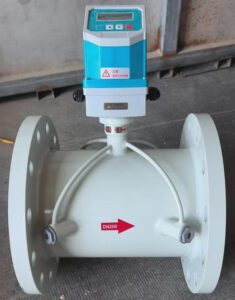
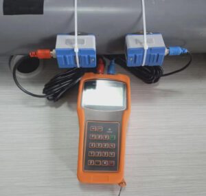
Clamp-on ultrasonic meters add no flanges. The transducers strap onto the outside of the pipe. That removes two flanged joints, two gaskets, and one possible leak path per measuring point.

Image: Aurloz, CC BY-SA 4.0, via Wikimedia Commons.
For a deeper look at the two ultrasonic styles, see Jade Ant’s comparison of clamp-on and transit-time non-invasive meters. For application ideas beyond skids, the ultrasonic flow meter applications guide shows where each style fits.
Trade-offs in precision: when to prioritize absolute accuracy over installation flexibility
Clamp-on meters trade some accuracy for flexibility. Published field studies show about 1% of reading in good conditions. On corroded or lined pipes, errors can reach several percent (2–5% in the studies Jade Ant cites).
So use this rule of thumb:
- Pick flexibility when you need trend data, leak detection, or a second check point.
- Pick absolute accuracy (inline magnetic, inline ultrasonic, or Coriolis) when the reading drives billing, batching, or a regulated record.
For steam or gas on a skid, Jade Ant’s vortex flow meter steam and gas guide explains when vortex is the better fit. The vortex flow meter datasheet page lists the actual ranges: 1.0% of reading on liquid, 1.5% on steam and gas, 20:1 turndown.
IV. The Selection Matrix: A Decision-Making Framework
Cost-benefit analysis: initial CAPEX vs. long-term OPEX
CAPEX is what you pay once. OPEX is what the end user pays every year. Skid builders usually see only CAPEX. The customer’s maintenance team lives with OPEX.
Here is a 10-year model for one DN50 line in conductive, water-based service. The numbers are assumptions, so replace them with your own quotes and labour rates.
| Cost (USD, 10 years) | Magnetic | Clamp-on ultrasonic | Vortex | Coriolis |
|---|---|---|---|---|
| Purchase | 1,800 | 2,600 | 1,500 | 6,500 |
| Installation | 700 | 300 | 800 | 900 |
| Calibration / verification | 1,500 | 2,000 | 1,800 | 1,200 |
| Pumping energy (pressure drop) | 0 | 0 | 318 | 3,175 |
| Maintenance and downtime | 900 | 400 | 1,500 | 800 |
| Total | 4,900 | 5,300 | 5,918 | 12,575 |
The energy line is real money. Pressure drop is the pressure the fluid loses passing through the meter, and the pump has to make it up. The formula is:
On a 20 m³/h line (0.00556 m³/s) with a 1.0 bar drop and 70% pump-motor efficiency, that is about 794 W. Running 4,000 hours a year at 0.10 USD per kWh costs about 318 USD per year, or 3,175 USD over ten years. The Coriolis share of the model is shown below. Coriolis pressure drops of 0.5–1.5 bar are cited in Jade Ant’s OEM accuracy guidance, so we used 1.0 bar.
Pumping energy is 25% of the total. That is the line most quotes leave out.
Industry insight: Coriolis is the right answer when you need direct mass flow at the best accuracy. It is rarely the right answer for a general water-based skid line. Match the tool to the tolerance, not to the brochure.
Installation complexity: “weld-in” vs. “clamp-on” or “flanged” options
Each mounting style changes your fabrication steps:
- Weld-in or spool-piece: best sealing, but needs welding and pressure test. Hard to service later.
- Flanged: the common choice. Two joints, two gaskets, bolt torque, leak test.
- Wafer: fits between two existing flanges. Saves space but needs good alignment.
- Clamp-on: no pipe cutting, quick to add, easy to move.
Gasket bore matters more than people think. Jade Ant’s field guidance says gaskets that protrude into the bore create turbulence at the meter inlet and cause a steady reading error, mostly on DN15–DN40 lines.
Integration speed: how meter types affect the assembly timeline
A clamp-on meter can be added after the skid is built and tested. An inline meter must be in the drawing from the first day. If your assembly schedule is tight, use this table to decide which meters go in early and which go in last.
| Meter style | When it goes in | Shop-floor impact |
|---|---|---|
| Weld-in / spool | Early, before pressure test | Adds welding and hydrotest steps |
| Flanged (magnetic, vortex, Coriolis) | During piping assembly | Adds fit-up, torque, leak checks |
| Clamp-on ultrasonic | After assembly, even in the field | No impact on the pressure test |
A weighted score you can reuse
Give each option a score from 1 to 5, multiply by the weight, and add.
Example for a conductive-water dosing skid:
| Option | Footprint (25%) | Install labour (20%) | 10-year TCO (25%) | Accuracy fit (20%) | Integration (10%) | Score |
|---|---|---|---|---|---|---|
| Magnetic | 4 | 4 | 5 | 4 | 5 | 4.35 |
| Clamp-on ultrasonic | 5 | 5 | 4 | 3 | 4 | 4.25 |
| Coriolis | 3 | 3 | 1 | 5 | 4 | 3.00 |
| Vortex | 2 | 3 | 3 | 3 | 4 | 2.85 |
Scores are illustrative. Change the weights to match your customer. If accuracy is 50% of the weight, Coriolis moves up.
V. Engineering for Compactness: Optimizing the Skid Footprint
Managing straight-run requirements: shorter piping without losing accuracy
Straight run is the length of straight pipe before and after a meter. Elbows and valves make the fluid swirl, and swirl causes error. The unit is D, the pipe’s inner diameter.
From Jade Ant’s documentation:
- Magnetic meter: about 5D upstream, 2–3D downstream.
- Turbine meter: 15D upstream, 5D downstream.
- Vortex meter: 10D minimum, 15D after one elbow, 20D after two elbows in different planes; 5D downstream.
- Coriolis meter: no straight-run requirement.
On a DN50 pipe (50 mm), D is 50 mm. The chart below shows the difference.
On four measuring points, choosing a magnetic meter over a worst-case vortex layout frees up 3 metres of straight pipe. That is a smaller frame and fewer supports.
If you cannot meet the straight run, you have three choices:
- Move the meter to a longer pipe section.
- Add a flow conditioner, which is a perforated plate that evens out the flow profile.
- Choose a meter that tolerates disturbed flow, such as Coriolis or a multi-path ultrasonic design.
Put the straight-run length on the P&ID. Fixing it on paper costs nothing. Fixing it after the frame is welded costs real money. For a deeper look at mass accuracy problems and installation causes, read Jade Ant’s OEM mass-flow accuracy solutions.
Integration of compact transmitters: from bulky head-mounts to integrated digital displays
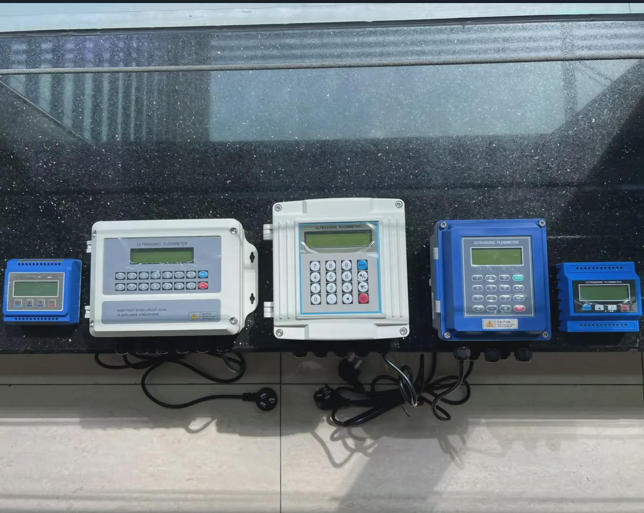
The transmitter is the electronics box that turns the sensor signal into an output. Three layouts are common:
- Head-mounted (integrated): the transmitter sits on the sensor. Fewest cables, but the electronics see the process heat and vibration.
- Remote-mounted: the transmitter sits on a panel, connected by a signal cable. Better for hot lines and awkward spots. Keep cable lengths within the manufacturer’s limit, typically 50–200 m depending on the sensor.
- Panel or DIN-rail: the transmitter mounts inside the skid’s control cabinet next to the PLC.

Image: Greinfelds, CC BY-SA 4.0, via Wikimedia Commons.
An integrated display also helps your customer. A technician can read flow at the skid without a laptop.
Manifold design: bypass loops and calibration ports
Plan for service while you design the pipe:
- Isolation valves upstream and downstream, so a meter can be removed or checked.
- A bypass loop if the process cannot stop.
- A calibration tee or a short straight spool where a portable clamp-on reference can sit.
- A low-point drain and high-point vent, so you can fill the pipe and bleed air before the zero check.
- A sight indicator where an operator needs a quick visual check.

Image: Cjp24, public domain, via Wikimedia Commons.
VI. Connectivity and Data Integration (The Digital Layer)
Protocol selection: 4–20 mA, Modbus, HART, or Profibus
A protocol is the language the meter uses to talk to the PLC.
| Protocol | What it carries | Best for |
|---|---|---|
| 4–20 mA | One value (flow) as a current | Any PLC, any age; simplest retrofit |
| Pulse | Totalizing as pulses | Batching and counting |
| HART | Digital data over the same 4–20 mA wires | Remote setup and diagnostics |
| Modbus RTU (RS-485) | Many values over one cable | Multi-meter skids and SCADA |
| Modbus TCP | Same data over Ethernet | Plant networks and cloud gateways |
| Profibus-DP | Fast fieldbus | Siemens-based control systems |
Jade Ant’s magnetic meters offer Modbus (RS-485), HART, and Profibus-DP, and its vortex meters offer the same family of options. The Turbines Incorporated protocol guide is a good primer for junior engineers. The Modbus Organization site hosts the open specification.
Cost-effective choice: if you have a Modbus-based PLC, use Modbus RTU on one RS-485 cable for all meters on the skid. If you only need flow, 4–20 mA is the cheapest to wire.
Watch the pulse rate. Jade Ant’s guidance gives an example: a meter that outputs 1,200 Hz at full scale into a PLC counter limited to 1,000 Hz will undercount at high flow. Check the meter’s maximum frequency against the PLC card before you order.
Signal conditioning: avoiding noise in high-density skid environments
A magnetic meter measures millivolts. Noise from a VFD can swamp that signal. Use this checklist from Jade Ant’s field work:
- Keep signal cables at least 300 mm from power and VFD output cables. Cross them at 90°.
- Use shielded twisted-pair cable and ground the shield at the transmitter end only.
- Keep the process ground resistance under 10 Ω.
- Use grounding rings on every plastic or lined pipe.
- Add a ferrite choke on the signal cable if noise only appears when a drive starts.
- Use an isolated signal converter if ground potential between the meter and the control room exceeds 1 V.
For the full diagnostic sequence, see Jade Ant’s magnetic flow meter troubleshooting guide, which shows the data behind these rules.
Remote diagnostics: using smart meters to reduce on-site technician visits
Smart meters report their own health. Over HART or Modbus you can read electrode impedance, coil current, empty-pipe alarms, and noise level. Plot them over time and you can see trouble coming.
Here is the rule of thumb. Healthy electrode impedance is far lower than the 100 kΩ warning level Jade Ant uses. A reading that creeps up from 50 kΩ to 80 kΩ in six months means fouling is on its way. Clean it at the next planned stop.
Newer ultrasonic designs add a web interface, so a technician with a phone can set up the meter without a laptop. Jade Ant’s smart ultrasonic flow meter with wireless and touchscreen setup covers that workflow. One chemical skid builder in that guide cut commissioning time by 40% on a 12-meter package (14 hours down to 8.4).
VII. Real-World Integration Case Studies
A note on these cases: The three cases below are worked examples built on stated assumptions. They are not customer testimonials. Replace our assumptions with your own to size the benefit on a real project.
Image: Jade Ant Instruments product photo.
Case A: Reducing footprint in a chemical dosing skid with clamp-on ultrasonic meters
Situation. A dosing skid has four DN25 lines. Each line has an inline meter, which means two flanged joints, two gaskets, and a short spool.
Change. The builder moves the line-monitoring points to clamp-on ultrasonic transducers. The pipe stays continuous.
Assumptions and math.
- Before: 4 meters × 2 joints = 8 joints at 1.25 h each = 10 h.
- After: 4 clamp-on sets at 1 h each = 4 h.
- Time saved: 6 h per skid, which is 450 USD at 75 USD per hour.
- At 60 skids per year, that is about 27,000 USD per year.
- Eight leak points are removed from every skid.
Watch-out. Clamp-on meters give about 1% in good conditions. If a line must dose within 0.5%, keep an inline meter on that line and use clamp-on for the rest.
Case B: Solving corrosion and clogging in a municipal water treatment skid
Situation. A treatment skid uses paddlewheel meters on backwash and chemical lines. Solids clog them. One chemical line attacks the sensor body.
Change. The builder switches to full-bore magnetic meters with a liner and electrode matched to the fluid. A full-bore tube has nothing to catch solids. Jade Ant’s liner and electrode selection guide maps materials to chemicals. Send your exact fluid data to the supplier before you order, because the wrong liner is the most expensive mistake on this list.
Assumptions and math.
- Paddlewheel replaced every 9 months: 320 USD part + 2 h labour at 75 USD = 470 USD per event.
- Annual cost per meter: 470 × (12 ÷ 9) ≈ 627 USD.
- Five meters: about 3,133 USD per year.
- Magnetic upgrade costs about 1,450 USD more per meter, or 7,250 USD for five.
- Payback: 7,250 ÷ 3,133 ≈ 2.3 years.
Case C: Scaling a modular HVAC skid for global export through standardized instrument selection
Situation. An HVAC skid builder ships to three regions. Each region had its own meter models, so the company kept nine meter variants (3 regions × 3 line sizes) and nine documentation packs.
Change. One magnetic meter family, three sizes, one Modbus register map, and a 4–20 mA fallback output.
| Item | Before | After |
|---|---|---|
| Meter variants | 9 | 3 |
| Documentation packs | 9 | 3 |
| PLC register maps | 3 | 1 |
| Spares per service centre | 9 types | 3 types |
Watch-out. Standard hardware does not mean standard certificates. CE, UL, CSA, and ATEX needs differ by market, and you should confirm each one for the exact model before you ship.
VIII. Installation and Commissioning Best Practices
The “first-run” protocol: step-by-step verification and zero-point calibration
Zero-point calibration means setting the meter to read exactly zero when nothing is flowing. It removes offset error. Run these steps in order. The checks follow Jade Ant’s calibration practical tips.
- Mechanical check. Gasket bore matches the pipe bore. Orientation is correct (electrodes at 3 and 9 o’clock on a horizontal pipe). The meter is supported, not hanging from the pipe.
- Grounding check. Measure resistance from the fluid to the earth bus. It should be under 10 Ω.
- Signal check. Confirm the scaling in the PLC matches the meter. Check the pulse frequency limit.
- Fill and bleed. Open the vent, fill slowly, and confirm the pipe is full.
- Zero check. Close both block valves so flow is truly zero. The display should read within ±0.05% of full scale.
- Five-point flow check. Compare readings at five stable flow rates against a reference meter. The reference should be at least four times more accurate than the meter under test.
- Record the baseline. Save electrode impedance, noise level, and coil current. This is your “healthy” reference for later.
Calculate the deviation at each point:
Avoiding common integration errors: improper grounding and air pocket entrapment
Grounding. Jade Ant’s field data puts grounding faults at 32% of calibration failures. Grounding rings are mandatory on plastic and lined pipe. Do not rely on flange bolts, because corroded threads break continuity.
Air pockets. Magnetic meters need a full pipe. Install them in a vertical upward run or at a low point. Avoid high points where air collects. Air causes unstable readings and low averages, and it is the first thing to rule out when a customer reports erratic flow.
Industry insight: Most skid-start problems are discovered in the first 48 hours. Build a post-startup zero check into your handover process. It is the cheapest warranty insurance you can buy.
Documentation for the end user: streamlined maintenance manuals for MRO teams
MRO teams do not read a 200-page manual. Give them a one-page sheet per meter:
| Section | What to include |
|---|---|
| Tag and location | Tag number, line, size, fluid |
| Baseline | Zero reading, impedance, noise, five-point results |
| Wiring | Terminal map, shield grounding point |
| Settings | Scaling, damping, protocol, register map |
| Schedule | Next verification date and method |
| Spares | Part numbers for the common wear items |
IX. Lifecycle Management and Total Cost of Ownership (TCO)
Wear and tear analysis: predicting the lifespan of wetted parts in aggressive media
Wetted parts are the parts that touch the fluid. In a magnetic meter those are the liner and the electrodes. Jade Ant lists these options for its intelligent electromagnetic meter:
| Part | Options | Typical reason to choose it |
|---|---|---|
| Liner | Neoprene, polyurethane, PTFE, F46, PFA | Neoprene for water, polyurethane for abrasion, PTFE or PFA for chemicals |
| Electrode | SS316L, Hastelloy B/C, titanium, tantalum, platinum-iridium | Match to the acid, base, or chlorinated fluid |
Plan for 10+ years by checking the fluid against the supplier’s compatibility table. Include cleaning agents and process upsets, not just the main chemical. A liner failure on a chemical line often costs several thousand dollars in downtime, far more than the price step up to a better liner.
Calibration intervals: strategies to extend service windows and reduce downtime
Calibration is checking against a trusted reference. A fixed interval for every meter wastes money. Start from the application:
| Application | Typical interval |
|---|---|
| Custody transfer or fiscal | 6–12 months |
| Pharmaceutical dosing | About 12 months |
| Chemical process monitoring | 12–24 months |
| Municipal water billing | 12–24 months |
| Non-fiscal process monitoring | 24–36 months |
Intervals from Jade Ant’s OEM accuracy guidance. Your jurisdiction and contract may require shorter ones.
Then extend the interval using data. Use the first two calibrations to measure real drift. Set the next interval at the point where drift would reach your accuracy limit, not before. Diagnostics help because a stable impedance and noise trend support a longer interval. The Fluke guide to flowmeter calibration practices stresses calibrating at real operating conditions, and the NIST metrological traceability guidance explains why a certificate needs an unbroken chain to a national standard.
Scalability: ensuring the meter can handle future capacity upgrades
Customers add capacity. Check the meter against the future flow, not just today’s.
Velocity is flow divided by pipe area:
On DN50, the area is about 0.001963 m². At 20 m³/h (0.00556 m³/s), velocity is about 2.8 m/s. Now check a vortex meter, with a liquid velocity range of 0.5–7 m/s:
- Lowest readable flow: 0.5 × 0.001963 × 3600 ≈ 3.5 m³/h.
- Highest readable flow: 7 × 0.001963 × 3600 ≈ 49.5 m³/h.
- Practical turndown: about 14:1.
If the customer upgrades to 50 m³/h, velocity is 7.07 m/s, just over the limit. A 10-minute check at the design stage prevents a field swap.
X. Future-Proofing Your Skid Systems
Summary of the integration playbook
Here is the whole approach in five steps:
- Define the fluid, the tolerance, and the environment before you open a catalogue.
- Compare technologies on footprint, install labour, and 10-year cost, not just accuracy.
- Put straight run, grounding, and service access into the P&ID.
- Choose a protocol that your PLC already speaks.
- Commission with a repeatable first-run test and give MRO a one-page record.
The shift toward “Smart Skids”: integrating IoT and predictive analytics
A smart skid reports its own health. Diagnostics from the meters feed a trend chart. The chart tells the customer which meter needs cleaning before an alarm goes off. For OEMs, that means fewer emergency calls and a service contract you can actually sell.
Final call to action: system harmony over individual component specs
A great datasheet does not save a bad layout. If you are choosing meters for a skid right now, send Jade Ant Instruments your fluid, line size, flow range, and environment through the Jade Ant contact page. Their application engineers can check straight run, liner, and protocol against your drawing before you release it.
For a second pair of eyes on clamp-on options, watch this walkthrough of how clamp-on ultrasonic meters are set up.

Video: “Clamp-on, Ultrasonic Flow Meters” by Thompson Equipment Company (TECO). Click the image to watch on YouTube.
Glossary of Key Terms
CAPEX / OPEX: CAPEX is one-time spending on buying and installing equipment. OPEX is the recurring cost of running it. Example: a 6,500 USD meter is CAPEX, and 318 USD of pump energy per year is OPEX.
Clamp-on meter: An ultrasonic meter whose sensors strap to the outside of a pipe. No cutting, no flanges.
Conductivity: How well a liquid carries electric current, in µS/cm. A magnetic meter needs about 5 µS/cm or more.
EMI / RFI: Electrical noise from motors, drives, and radios that can disturb a weak meter signal.
Flow conditioner: A plate or tube bundle that evens out the flow before a meter, so you need less straight pipe.
HART / Modbus / Profibus: Digital communication methods. HART rides on 4–20 mA wires. Modbus and Profibus connect many devices to a PLC.
Pressure drop: Pressure lost as fluid passes through a device. Example: a 1.0 bar loss across a Coriolis meter costs about 318 USD per year in pump energy on a 20 m³/h line running 4,000 hours.
Straight run: The length of straight pipe a meter needs before and after it so the flow settles. Measured in pipe diameters (D).
TCO (Total Cost of Ownership): All costs over the life of the meter: purchase, install, calibration, energy, maintenance, and downtime.
Turndown: The ratio between the highest and lowest flow a meter reads accurately. Example: 14:1 means it reads from 100% down to about 7%.
Zero-point calibration: Setting the meter to read zero when flow is truly zero.
Frequently Asked Questions
1. How do I minimize the required straight-run piping to keep my skid footprint small?
Start by picking a meter with a short requirement. A magnetic meter needs about 5D upstream and 2–3D downstream, while a vortex meter can need 10–20D upstream. On a DN50 line, that is 250 mm against up to 1,000 mm. If space is still tight, add a flow conditioner, move the meter to a longer pipe section, or choose a Coriolis meter, which has no straight-run requirement. Write the length on the P&ID before the frame is built.
2. Which flow meter is most resilient to vibration, and how do I prevent signal interference in a dense skid?
Magnetic meters have no moving parts, so they handle pump vibration well. Jade Ant’s vortex meters are rated for 10–200 Hz at 2 g. Coriolis meters are the most sensitive, because outside vibration near the tube’s natural frequency can disturb the signal. For interference, keep signal cables 300 mm from power cables, use shielded twisted pair, ground the shield at the transmitter end only, and keep process ground resistance under 10 Ω. If noise appears only when a drive starts, a ferrite choke often fixes it.
3. For international exports, which certifications (UL, CE, CSA) are critical for my flow meter selection?
It depends on the destination. The European Commission explains that CE marking shows a product was assessed against EEA safety, health, and environmental requirements, so it is the baseline for Europe. North American projects often ask for UL or CSA listings, and the local inspector decides. For hazardous areas, ask for ATEX or IECEx. Certification belongs to a specific model, so request the certificate for the exact part number before you ship.
4. How does the choice of flow meter affect the overall pressure drop and pump sizing of the system?
Every restriction adds head the pump must overcome. Magnetic and ultrasonic meters add almost none. Jade Ant lists vortex at about 5–15 kPa and Coriolis at 0.5–1.5 bar. Use to turn that into watts. On a 20 m³/h line, a 1.0 bar drop at 70% efficiency is about 794 W. Add the meter’s loss to your system curve before you pick the pump.
5. Can ultrasonic meters replace Coriolis meters in high-precision dosing, and what are the risks of clamp-on meters in a permanent OEM installation?
Usually not for tight dosing. Coriolis reaches about 0.1–0.2% and measures mass directly. Clamp-on ultrasonic gives about 1% in good conditions, and several percent on corroded or lined pipe. Use clamp-on for monitoring, leak detection, and secondary points. The main risks in a permanent installation are pipe-wall condition, poor coupling, and dried couplant, which should be inspected every two to three years. If the skid is shipped with the meter fitted, record the acoustic signal strength at commissioning so the next technician has a baseline.
6. What is the most cost-effective way to integrate flow monitoring into a Modbus-based PLC?
Put all meters on one RS-485 cable using Modbus RTU, and give each a unique address. Use the same register map for every skid you build, so one PLC program works everywhere. Keep a 4–20 mA output as a backup for simple signals. Check the pulse frequency limit if you also use pulse outputs, because a 1,200 Hz meter on a 1,000 Hz input will undercount.
7. Which materials are best for flow meters handling aggressive chemicals to ensure a 10+ year lifespan?
There is no single best material. PTFE and PFA liners resist most chemicals. Polyurethane or ceramic handle abrasive slurry better. Electrodes range from 316L stainless for mild fluids to Hastelloy, titanium, or tantalum for aggressive ones. Send the supplier the full fluid list, including cleaning agents, pH range, and temperature peaks. When in doubt, step up one liner grade, because the price gap is small next to a liner failure.
8. How can I simplify field calibration and reduce installation labour hours for my end users?
Design for it. Add isolation valves, a calibration tee, and a vent so verification does not need a shutdown. Use the transmitter’s zero check and diagnostics for annual verification, and a portable clamp-on as a cross-check within about 1%. For labour, pre-configure meters before they reach the skid, use bulk configuration tools, and standardize on one meter family. One chemical skid builder cut commissioning from 14 hours to 8.4 by moving to web-based setup and Modbus TCP.
9. In what scenarios should I prioritize a vortex meter over a magnetic flow meter, and how does viscosity affect accuracy?
Choose vortex for steam, gas, and non-conductive liquids, where a magnetic meter cannot work. Choose magnetic for conductive liquids, dirty fluids, and low pressure drop. Viscosity hurts vortex accuracy above about 5 cP, because the swirls form less cleanly. Magnetic meters read independently of viscosity as long as conductivity is at least about 5 µS/cm. Check the cold-start viscosity, since a fluid that is thin at 60 °C can be thick at 15 °C.
10. What are the red flags to look for when reviewing a flow meter’s technical datasheet for OEM use?
Watch for these:
- Accuracy stated “at reference conditions” only, with no field figure.
- No stated straight-run requirement, or only a footnote.
- No pressure-drop curve at your flow rate.
- A velocity or flow range that does not cover your future capacity.
- No mention of gas pockets or two-phase flow, which no meter fully ignores.
- Missing liner and electrode compatibility data for your fluid.
- Protocols listed without a register map.
- Certificates shown for a “series” instead of your exact model.
- No stated calibration interval or verification method.