Ultra Flow Meter Selection: A Spec Guide for Engineers
Thesis: Selecting the right ultra flow meter means lining up three things: fluid chemistry, operating conditions, and installation limits. Get those right and you keep measurements accurate for years, lower lifecycle cost, and avoid unplanned downtime on high-stakes lines.
I. Introduction
A skid builder orders a DN100 meter because the pipe is DN100. At commissioning, the line runs at 6 m³/h. That is only 0.21 m/s inside the meter. The reading jumps around, the PLC alarms, and the project slips two weeks.
Nothing was defective. The meter was simply sized to the pipe instead of the process.
This is the daily reality for the buyers we work with: OEM equipment and skid-mount manufacturers, instrument distributors, EPC and system integrators, industrial terminal and MRO teams, and municipal utilities. Flow data drives dosing, billing, batching and control. If the number is wrong, money leaks out quietly.
Two mistakes cause most of the pain:
- Over-specification. You pay for 0.1% accuracy on a line where the control valve itself has 2% deadband.
- Under-specification. You buy the cheapest meter, and it fails on the first acid batch or the first slug of air.
In this guide, an ultra flow meter means any high-accuracy, low-maintenance industrial meter built for demanding duty. Electromagnetic, vortex, Coriolis and ultrasonic designs all fit. The goal is a repeatable way to specify one that balances performance and cost. At Jade Ant Instruments, we use the same logic you will see in our flow meter selection guide.
The short version: work in this order: Fluid → Process → Installation → Integration. Then check lifecycle cost and supplier support before you sign.
Prefer to watch first? This walkthrough from FTI Flow Technologies covers the basic selection logic.
II. Assessing Fluid Properties and Chemical Compatibility
The medium decides how long the meter lives and how well it measures. Start here, because no installation trick can fix a wrong technology choice.
Viscosity, Density and Conductivity Narrow the Field
Three properties do most of the filtering.
- Conductivity is how well a liquid carries electricity. An electromagnetic (“mag”) meter needs at least about 5 µS/cm. Tap water is roughly 300–800 µS/cm, and most acids and bases are far higher. Deionized water and hydrocarbon oils fall outside the window.
- Viscosity is how thick a fluid is. Mag meters ignore it. Vortex meters struggle as it climbs, so the vortex guidance in our steam and gas vortex guide flags liquids above about 5 cP for correction factors.
- Density matters when you need mass flow. A Coriolis meter measures mass and density directly. Other meters measure volume, so you must compensate when density changes.
| Question | If yes | If no |
|---|---|---|
| Is the liquid conductive (≥5 µS/cm)? | Electromagnetic is a strong first choice | Look at Coriolis, ultrasonic or vortex |
| Do you need mass flow or density? | Coriolis | Volumetric meters are fine |
| Is it steam or gas? | Vortex or thermal types | Mag or ultrasonic for liquids |
| Is the fluid thick or variable in viscosity? | Coriolis or positive displacement | Most technologies work |
Plain-English definition: Turndown means how wide a range a meter can measure accurately. A 20:1 turndown on a 120 m³/h meter means it stays accurate down to 6 m³/h. We use it again in Section III.
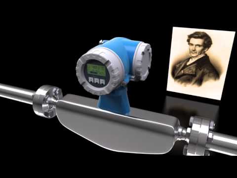
Here is a Coriolis meter, which measures mass flow directly.

Photo: KROHNE, CC BY-SA 4.0, via Wikimedia Commons.
Endress+Hauser’s short animation shows why the tubes twist in proportion to mass flow.
Material Compatibility Prevents Corrosion and Contamination
In acid, caustic or wastewater service, wetted materials matter more than any datasheet accuracy figure. The liner touches the fluid across the whole bore. The electrodes pick up the signal at two small points. Both must survive your chemistry.
| Liner | Typical temperature range | Best for | Watch out for |
|---|---|---|---|
| Hard rubber | 0 to +80 °C | Municipal water, wastewater, mild slurries | Not for strong acids or solvents |
| PTFE | −40 to +180 °C | Strong acids, bases, solvents | Can detach under sustained vacuum |
| PFA | −40 to +150 °C | Pharma, ultrapure water | Check vacuum data |
| Polyurethane | −20 to +50 °C | Abrasive mining slurries | Low temperature ceiling |
| Ceramic (Al₂O₃) | 0 to +180 °C | Very abrasive slurries | Higher cost |
| Neoprene | −10 to +80 °C | Raw water, cooling towers | Limited chemical range |
For electrodes, 316L stainless suits most water duty. Hastelloy C-276 handles mixed acids. Titanium suits chlorinated media and seawater. Tantalum is reserved for the harshest hot-acid service. Our liner and electrode sizing guide goes deeper, and the magnetic flow meter guide for water and chemical service maps these choices to specific applications.
Industry insight: A chlor-alkali plant saw 316L electrodes pit within 14 months in brine at roughly 3,500 ppm chlorine. After a switch to titanium, the same meter ran seven years. A $1,800 sensor head avoided far more in lost production.
If you serve drinking water, check that wetted parts meet NSF/ANSI/CAN 61. For food contact, PTFE falls under FDA 21 CFR 177.1550.
Multi-Phase Flow: Air, Bubbles and Solids
Most meters are designed for one phase at a time. Air in a liquid line is the most common reason a good meter reads badly.
| Condition | Electromagnetic | Coriolis | Vortex |
|---|---|---|---|
| Entrained air or bubbles | Reads drift high or erratic if the pipe is not full | Mass and density readings become unstable | Bubbles create noise the sensor can mistake for flow |
| Suspended solids | Excellent, because the bore is fully open | Works, but check abrasion and pressure drop | Poor above about 5% solids |
| Partly filled pipe | Not suitable | Not suitable | Not suitable |
Fix air at the design stage. Install the meter at a low point or on a vertical upward run, and keep control valves downstream. For conductive slurries, a mag meter with a ceramic or polyurethane liner is usually the safest bet.
III. Defining Process Parameters and Operational Limits
Clear boundaries stop early failures and slow measurement drift. Write them down before you ask for a quote.
Turndown Ratio: Match the Meter to Your Real Flow Range
Turndown is the maximum flow divided by the minimum flow you need to measure:
Velocity through the meter is:
Worked example. A dosing skid runs from 6 m³/h up to 120 m³/h. That is 20:1.
| Meter bore | Velocity at 6 m³/h | Velocity at 120 m³/h | Verdict |
|---|---|---|---|
| DN100 | 0.21 m/s | 4.24 m/s | Too slow at the low end |
| DN80 | 0.33 m/s | 6.63 m/s | Both ends inside the typical 0.3–10 m/s mag meter window |
Fitting a DN80 meter into a DN100 line with reducers fixes the problem at low cost. Our sizing notes show that raising velocity from 0.30 to about 0.47 m/s can cut measurement uncertainty by up to 38%.
Industry insight: Size to your normal range, not the design maximum. Many lines spend 80% of their hours at 30% of capacity.
Vortex meters work the other way around. They need enough velocity to shed stable vortices, so they are usually sized to the pipe, and the 20:1 standard turndown (40:1 extended) does the work.
Temperature and Pressure Extremes
Temperature and pressure decide seals, liners and electronics.
- Match the pressure rating (PN or ANSI class) to your maximum allowable working pressure, with margin.
- Check liner limits against peak temperature, including cleaning cycles and steam-out.
- For gas and steam, use pressure and temperature compensation. Without it, density changes create errors that never go away.
- For high-temperature service, our vortex range covers −40 to +350 °C, with higher options on request.
Watch for vacuum. A PTFE liner can collapse inward under sustained vacuum unless it is mechanically backed. This is common in batch reactors, so ask for the vacuum data sheet.
Flow Profile: Do You Need a Flow Conditioner?
A flow profile is the shape of the velocity across the pipe. Elbows, valves and pumps distort it. A flow conditioner is a plate or tube bundle that straightens the flow before it reaches the meter.

Photo: Cmarcante, public domain, via Wikimedia Commons.
Our vortex flow meter needs about 15 pipe diameters (15D) of straight pipe upstream after a single elbow, and 5D downstream. After a control valve, plan for 30D or more. If you cannot get there, a conditioner installed upstream can cut the requirement to roughly 10D.
Data: Jade Ant Instruments service-record analysis, 312 reported vortex field issues.
IV. Determining Required Accuracy and Repeatability
Match precision to the job. You pay for every extra decimal place, so buy only what the application uses.
Custody Transfer Versus Process Control
Custody transfer means money changes hands based on the reading. It is legally binding, so you need the best accuracy and proof that it holds over time. Process control means the reading steers a valve or pump. There, stability matters more than the last 0.1%.
| Application | Typical accuracy target | Typical technology |
|---|---|---|
| Custody transfer, fuel, high-value fluids | 0.1–0.5% of reading | Coriolis, multi-path ultrasonic |
| Municipal billing meters | 0.5% or better, often per OIML R49 | Electromagnetic, ultrasonic |
| Chemical dosing | 0.2–0.5% | Electromagnetic, Coriolis |
| Steam and gas monitoring | 1.0–1.5% | Vortex |
| Retrofit monitoring, audits | 1–2% | Clamp-on ultrasonic |
Water meters sold for billing are commonly type-tested under the OIML R 49 recommendation, so ask for it if your regulator expects it.
Industry insight: Read the accuracy statement carefully. “±0.5% of reading” stays tight at low flow. “±0.5% of full scale” can mean 5% error when you are running at 10% of range.
Repeatability and PID Loop Stability
Accuracy is how close you are to the true value. Repeatability is how consistently the meter reads the same flow under the same conditions.
A PID loop reacts to changes. A meter with a small steady bias but excellent repeatability can control well. A meter with good lab accuracy but noisy readings makes the loop hunt, and the valve chatters.
Also check your error budget. If the control valve has about 2% deadband, a 0.2% meter will not improve real control. Put that money into installation quality and signal integrity instead. Our five-factor selection method uses the same “system error” thinking.
The Cost of Error: What 1% Really Means
Convert accuracy into money before you decide:
A utility district meter passes 1,500,000 m³ per year at $1.10 per m³:
That is one meter and one percentage point. A dosing skid using $100,000 of chemical per year loses $1,000 for every 1% of over-dosing. Compare those figures with the price gap between a 0.5% and a 0.2% meter. The answer is often obvious.
V. Evaluating Installation Constraints and Integration Factors
A high-spec meter will still fail if the pipe is not built for its technology. This is where most “bad meter” complaints begin.
Straight-Run Requirements
Straight run is the length of undisturbed pipe before and after the meter. It gives the flow time to settle into a steady, symmetrical profile. Typical requirements after a single 90° elbow:
Source: manufacturer guidance summarized in our installation guide. Always confirm your model’s manual.
To calculate the length, multiply the diameter by the “D” number. A DN100 vortex meter needs 15 × 0.1 m = 1.5 m upstream at minimum. Our installation best practices guide lists requirements for other fittings.
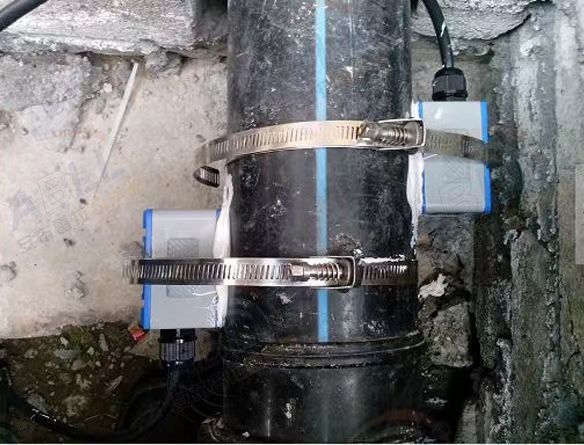
If space is tight, a clamp-on design can sidestep some of the risk. The clamp-on versus transit-time comparison explains when it works and when it does not.
Mechanical Integration: Flanges, Mounts and Weight
For skid-mount builders, the physical fit matters as much as the electronics.
| Choice | What to check |
|---|---|
| Flange standard | ANSI B16.5, DIN 2501, JIS B2220 or GB/T 9119 must match your pipe spec |
| Wafer vs. flanged vs. threaded | Wafer saves length and weight; flanged is easier to service; threaded suits small bores |
| Weight | Coriolis units are heavier, so plan supports and skid frame loads |
| Orientation | Mag meters prefer vertical upflow or electrodes at 3 and 9 o’clock |
| Alignment | Flanges concentric within about 1/16 inch to avoid stress on liners or tubes |
Jade Ant Instruments builds to non-standard flanges and connection types on request, which saves rework when your drawing differs from the catalog.
Environment: Vibration, EMI/RFI and IP Rating
- Vibration from pumps can fake a signal on vortex meters and strain Coriolis tubes. Support the pipe and keep the meter away from the source.
- EMI/RFI (electromagnetic and radio-frequency interference) comes from VFDs, large motors and welders. Keep signal cables about 300 mm from power cables and use shielded pairs.
- IP rating shows dust and water protection. IP65 is a common baseline. IP67 and IP68 suit washdown, flooding and buried pits.
Grounding is the single biggest installation issue for mag meters. A 2024 analysis of 1,247 service tickets by Soaring Instrument found that half traced to grounding.
Real case: A food plant in the Netherlands saw 8–12% reading swings on an HDPE line. Three service visits found no hardware fault. A fourth technician fitted grounding rings and connected them to the plant earth. The swing fell below 0.3% within minutes.
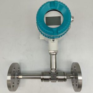
Here is a mag meter body for reference. Note the flanges, which is where grounding rings sit.

Photo: KROHNE, CC BY-SA 4.0, via Wikimedia Commons.
VI. Signal Output and Control System Compatibility
EPCs and system integrators want plug-and-play. That only happens when outputs, power and certifications are chosen together.
Choosing the Right Protocol for Your PLC
| Protocol | Plain-English meaning | Best fit |
|---|---|---|
| 4–20 mA | An analog current signal, simple and noise-tolerant | Almost every PLC and DCS input card |
| HART | Digital data carried on the same 4–20 mA wires | Remote setup and diagnostics |
| Modbus | A common serial or Ethernet language for SCADA | General plants, BMS, data loggers |
| PROFIBUS / PROFINET | Siemens-ecosystem fieldbus and Ethernet | Siemens-based DCS |
| EtherNet/IP | Industrial Ethernet used on Rockwell-style PLCs | Allen-Bradley architectures |
Our standard outputs are 4–20 mA, pulse, HART and Modbus RS-485. Other fieldbuses are available as options on some models, so ask early. A protocol mismatch found late can add $500–$1,500 per point for external converters.
Local Versus Remote Display
Operators and MRO crews need to read the flow without opening a laptop. A local LCD saves a walk to the control room. If the meter sits in a hot, wet or hard-to-reach place, a remote transmitter keeps electronics in a safer spot. Choose based on who will actually look at the number, and where they stand.
Power Supply and Hazardous Areas
A common supply for vortex designs is 24 VDC (18–36 V), with 220 VAC and lithium battery options for remote sites. Check power draw if you are running off solar.
In explosive atmospheres, treat certification as part of the design, not an add-on. The ATEX Directive 2014/34/EU covers equipment for the EU market. The IECEx scheme covers international certification. Define the zone, gas group and temperature class first. Then select the meter, barriers and cabling as one system.
For safety-instrumented functions, ask for a SIL rating under IEC 61508. Our ultrasonic applications guide also covers compliance for non-contact designs in hazardous areas.
VII. Total Cost of Ownership (TCO) and Lifecycle Analysis
The purchase price is only part of the bill. Reliability over ten years is the real measure of value.
Here is a modeled 10-year cost for one DN50 electromagnetic meter on municipal wastewater (24/7 duty):
Purchase is about 36% of the total. The other 64% is installation, calibration, spares and downtime. Treat any quote without those lines as incomplete.
Maintenance Intervals: Calibration Versus Self-Diagnostics
Calibration is a scheduled proof of accuracy. A typical cycle for general process meters is every 2–3 years. Billing and custody points are usually checked annually. Many modern meters add in-situ verification, which tests coils, electrodes and electronics without removing the meter. This can extend the interval and cut the cost of bypass piping and rental meters. For traceability, look for a chain back to national standards such as NIST liquid flow calibration.
Wear and Tear in Abrasive Media
Plan for the consumable part. In mag meters, that is the liner and sometimes the electrodes.
Industry insight: A titanium dioxide slurry line at 30% solids wore through polyurethane liners in 8 months. Ceramic liners at the same points ran more than 4 years. The ceramic option cost more upfront and saved a shutdown every year.
Velocity matters too. Above about 10 m/s, liner erosion speeds up. Meters with moving parts, such as turbines, add bearings to the wear list. Our turbine meter guide for distributors explains why upstream filtration decides bearing life.
Lead Times and Spare Parts
For MRO and utility teams, a meter that takes 12 weeks to replace is a risk even if it never fails. Jade Ant Instruments quotes the following lead times:
| Order type | Typical lead time |
|---|---|
| Standard models, 1–10 units | 1–2 weeks |
| Standard models, 11–50 units | 2–3 weeks |
| Custom or modified models | Engineering review 3–5 days, production 3–4 weeks, testing 3–5 days |
Common wear parts, sensor modules, electronics, gaskets and O-rings are kept in stock for quick shipment. Ask every supplier for the same information in writing.
Spreadsheet-ready TCO template (copy into Excel):
| Cost line | Meter A | Meter B | Meter C |
|---|---|---|---|
| Purchase price | |||
| Installation and wiring | |||
| Straight-run or piping changes | |||
| Calibration over 10 years | |||
| Spare parts and wear items | |||
| Pressure-loss energy cost | |||
| Estimated downtime cost | |||
| 10-year total |
VIII. Strategic Supplier and Integrator Qualification
Technical support is as valuable as the hardware. When a meter misbehaves at 2 a.m., you need an engineer, not a call queue.
Case Studies and Reference Sites
Ask for references in your industry, with similar fluid, size and protocol. Good references include the application, what went wrong first, and the measured result. For example, a 150 MLD water plant in Shandong, China reported zero unplanned mag meter outages over 18 months and a 12% drop in coagulant use after upgrading its dosing meters. That is the kind of specific outcome to request.
If you are comparing suppliers broadly, our manufacturer comparison shows how different brands position their strengths.
Engineering Support for Complex Skid Designs
OEMs need more than a catalog number. Ask whether the supplier can:
- Modify flange types, face-to-face lengths and mounting.
- Adjust output ranges, firmware and protocols.
- Supply special materials such as titanium, Hastelloy or duplex stainless.
- Support white-label or private-label branding.
- Witness or run a Factory Acceptance Test (FAT) on your units.
Jade Ant Instruments supports OEM/ODM work, with custom development typically taking 4–6 weeks. You can read about our factory and engineering team before you reach out.
Warranty and After-Sales Calibration
Do not accept “warranty included” without terms. Ask for the period, what it covers, who pays freight, and how long repair takes. Then confirm calibration support: certificates with each unit, periodic re-calibration, firmware updates and spare-parts pricing. We list extended warranty options and calibration and verification services, and quotes come back within 48 hours. When you are ready, you can request a quote with your process data.
IX. Critical Questionnaire for Technical Procurement
A standard inquiry set removes guesswork. Send these questions to every supplier so you compare like with like.
Fluid-Specific Questions
| Question | Why it matters | Example answer |
|---|---|---|
| What is the fluid and concentration? | Sets liner and electrode material | 15% HCl |
| What is the pH range? | Corrosion and coating risk | pH 1–2 |
| What is the conductivity? | Decides whether mag is possible | 12,000 µS/cm |
| What is the solids content and size? | Abrasion and fouling | 8% by weight, fine silt |
| What is the viscosity at temperature? | Affects vortex, turbine, Coriolis | 3 cP at 45 °C |
| Is air or gas ever present? | Causes reading errors | Air during pump start |
Process-Specific Questions
| Question | Why it matters | Example answer |
|---|---|---|
| Minimum, normal and peak flow? | Sizing and turndown | 6 / 40 / 120 m³/h |
| Operating and peak temperature and pressure? | Rating and seals | 60 °C, 10 bar, 90 °C steam-out |
| Required pulse frequency? | Totalizer and PLC input limits | 0–1,000 Hz |
| Required sampling or update rate? | Fast batching vs. slow monitoring | 100 ms |
| Straight run available? | Technology choice | 4D upstream |
| Vacuum or pressure cycling? | Liner choice | Batch vacuum to −0.5 bar |
Compliance and Certification Questions
| Question | Why it matters | Example answer |
|---|---|---|
| Is a food or pharma approval needed (FDA, 3-A)? | Wetted material and surface finish | FDA 21 CFR 177 |
| Does the meter touch drinking water (NSF 61)? | Municipal requirement | Yes |
| Is a hazardous-area rating needed? | ATEX or IECEx zone | Zone 1, IIB T4 |
| Is a SIL rating required? | Safety systems | SIL 2 |
| Is traceable calibration required? | Billing and audits | Annual, with certificate |
X. Conclusion
Every good specification follows the same path: Fluid → Process → Installation → Integration. Fluid chemistry picks the technology and materials. The process range sets size, turndown and ratings. The installation decides whether the meter can perform at its datasheet accuracy. Integration makes sure the signal reaches the control system without drama.
The payoff is practical. Commissioning goes faster. Fewer “mystery” readings reach your service desk. Unplanned downtime drops because the meter was built for the job, not just the pipe size.
Prioritize technical validation over the lowest bid. A $1,200 saving at purchase can become a $20,000 problem when a liner fails or a loop misbehaves. Send your fluid, flow range, pipe size, temperature, pressure, outputs and installation limits to the engineers at Jade Ant Instruments, and we will return a clear recommendation, not just a model number.
Quick Glossary
| Term | Simple meaning |
|---|---|
| Turndown | Ratio of highest to lowest flow a meter measures accurately |
| Straight run | Length of straight pipe before and after the meter, measured in pipe diameters (D) |
| Conductivity | How well a liquid carries electricity, in µS/cm |
| Liner | The inner coating of a mag meter that touches the fluid |
| Repeatability | How closely the meter repeats the same reading under the same conditions |
| Custody transfer | A sale or hand-over point where the flow reading sets the price |
| Flow conditioner | A plate or tube bundle that straightens flow before the meter |
| EMI/RFI | Electrical or radio noise that disturbs signals |
| SIL | Safety Integrity Level, a rating of risk-reduction performance |
| TCO | Total cost of ownership over the meter’s life |
FAQ: Questions Professional Buyers Ask
1. How do I determine if my fluid requires a conductive or non-conductive flow meter?
Measure the conductivity. If it is at or above about 5 µS/cm, an electromagnetic meter can work. Tap water, acids, bases and slurries usually qualify. If the fluid is below that level, such as deionized water, oil or solvents, choose ultrasonic, Coriolis or vortex.
2. What is the minimum straight-run requirement for an ultra flow meter to maintain specified accuracy?
It depends on the technology. After one elbow, typical needs are 5D upstream for electromagnetic, 10D for ultrasonic and turbine, 15D for vortex, and almost none for Coriolis. Downstream, plan for 3–5D. Always confirm in the model’s manual.
3. How does entrained air affect the measurement of liquid flow in Coriolis versus mag meters?
In a Coriolis meter, bubbles disturb the vibrating tubes, so mass and density readings become unstable. In a mag meter, bubbles or a partly filled pipe change the conducting area, so the reading drifts. Both need a full, bubble-free pipe. Remove the air with proper piping, air release valves and downstream control valves.
4. Can your flow meters be integrated into an existing SCADA system via Modbus TCP/IP?
Our standard digital output is Modbus RTU over RS-485, plus 4–20 mA, pulse and HART. If your SCADA needs Modbus TCP/IP, the usual approach is a Modbus RTU-to-TCP gateway. Tell us your network needs when you request a quote so we can confirm the exact option for your model.
5. What materials are recommended for highly abrasive slurries to prevent liner wear?
Use a ceramic (Al₂O₃) liner for severe abrasion, or polyurethane for moderate abrasion at lower temperatures. Keep velocity below about 10 m/s. In one titanium dioxide line, ceramic outlasted polyurethane by roughly six times.
6. How do I calculate the optimal turndown ratio for a process with highly fluctuating flow rates?
Divide your peak flow by your lowest flow you must measure. For example, 120 m³/h ÷ 6 m³/h = 20:1. Then check velocity at both ends in the meter bore. If the low-end velocity is too slow, reduce the bore with reducers.
7. What are the differences in certification requirements for municipal water versus industrial chemical applications?
Municipal water usually needs drinking-water material approval such as NSF/ANSI/CAN 61 and often an OIML R49-based accuracy approval for billing. Industrial chemical service focuses on material compatibility, hazardous-area approvals (ATEX or IECEx) and sometimes SIL ratings.
8. How often should the meter be recalibrated to maintain custody-transfer accuracy?
Annually is the common baseline for billing and custody points. Your regulator, contract or standard may require shorter intervals. In-situ verification tools can document that the meter has not drifted, but they do not replace traceable calibration.
9. Can the meter be installed in any orientation (vertical versus horizontal), and how does this affect the signal?
Not any orientation. For liquids, vertical upward flow keeps the pipe full and carries air past the sensor. In horizontal pipes, keep mag electrodes at the 3 and 9 o’clock positions, not at the top. For steam and gas, mount horizontally and drain condensate downstream.
10. What is the impact of fluid temperature fluctuations on the zero-point stability of the meter?
Temperature swings can shift electronics and sensor behavior, so the zero reading may drift slightly. Better meters compensate automatically. You can reduce the effect by insulating the pipe, shading outdoor transmitters, and doing a zero-flow check at normal operating temperature.
11. How do I troubleshoot signal noise caused by Variable Frequency Drives (VFDs) near the meter?
Start with wiring. Route signal cables at least 300 mm away from VFD and power cables, and use shielded twisted pair grounded at one end. Check the meter’s earth connection and, for mag meters, the grounding rings. If noise persists, add line filters at the VFD and move the meter or cable path.
12. What is the typical lead time for customized flange specifications for OEM skid integration?
For standard models, expect 1–2 weeks for small orders. For customized builds, plan for 3–5 days of engineering review, 3–4 weeks of production and 3–5 days of testing. Full custom development typically runs 4–6 weeks. Lead times are confirmed in writing with your quote.