A Comprehensive Guide to Mass Flow Rate Units for OEM Manufacturers

1. Why Mass Flow Rate Accuracy Is Non-Negotiable in Industrial Applications
A North American petrochemical distributor submitted a $120,000 instrument quote specifying flow output in kg/h. The client’s existing DCS (Distributed Control System) — a legacy platform installed in 2009 — was configured throughout in lbm/h. The purchasing manager caught the unit mismatch before sign-off and asked for a revision. The distributor’s team didn’t know how to handle the conversion professionally. The client reordered from a competitor who did.
The equipment was identical. The price was comparable. The difference was a unit specification error that one team could navigate and the other could not.
This happens more often than most engineering businesses track — because unit-related losses rarely appear as a line item in lost-order analyses. They surface as vague notes: “client wanted a different specification,” “couldn’t align on technical requirements,” “went with another supplier.” The root cause is almost always the same: someone on the team did not master the measurement language their client was working in.
Three Categories of Pain That Unit Errors Create
Calibration errors occur when a meter leaves the factory calibrated in one unit and arrives at site where the control system expects another. If no one catches the discrepancy before commissioning, the meter transmits a value that is mathematically wrong — not out of range, not alarmed, just incorrect — for as long as it runs.
Unit confusion during integration is particularly damaging on EPC projects, where instruments arrive from multiple vendors, each with its own factory defaults. A Coriolis meter defaulting to kg/h and a thermal mass meter defaulting to SLPM feeding the same PLC process block creates a data inconsistency that the PLC resolves by displaying a number that is a meaningless combination of both.
Regulatory non-compliance is the most expensive outcome. A water utility whose billing meters are configured in m³/h instead of the regulator-required Nm³/h equivalent, or a pharmaceutical batch record showing liters when FDA 21 CFR Part 211 requires mass-based documentation, creates audit findings that shut down production lines while the discrepancy is investigated and corrected.
This guide is the reference that OEM skid-mount manufacturers, instrument distributors, EPC integrators, MRO teams, and municipal utilities need to prevent all three — from the specification stage through commissioning and into long-term operation.
2. Understanding Mass Flow Rate: Definition and Core Principles
Mass flow rate (written as ṁ in engineering notation, where the dot above the m indicates “per unit time”) is the mass of fluid passing through a measurement point per unit of time. The unit is always some mass unit divided by some time unit: kilograms per hour, pounds per minute, grams per second.
This is different from volumetric flow rate, which measures the volume of fluid passing through a point per unit of time — liters per minute, cubic meters per hour, gallons per minute.
Volume is what you see in the pipe. Mass is what you actually own.
Why the Distinction Matters — Especially for Gases
A tanker truck delivers LPG by mass, not by volume, because a liter of propane at 40°C and a liter of propane at 5°C contain different amounts of fuel even though they occupy the same volume. The chemistry, the energy content, and the commercial value are all determined by mass — not the space the fluid happens to occupy at that moment.
Gases make this even more stark. A gas measured at 8 bar and 80°C occupies approximately one-tenth the volume it would at atmospheric pressure and 15°C. A volumetric meter on that gas line — without pressure and temperature compensation — produces a reading that is a function of operating conditions rather than actual gas quantity. The reading looks plausible. It may never trigger an alarm. But it is systematically wrong every time the line pressure or temperature changes.
The formula connecting mass flow rate, volumetric flow rate, and fluid density is:
Where ṁ is mass flow rate (kg/h), Q is volumetric flow rate (m³/h), and ρ (rho) is fluid density at actual process conditions (kg/m³). For a gas whose density changes with pressure and temperature, this means the volumetric reading and the mass flow rate are only equal at one specific set of conditions — the reference conditions — and diverge at every other operating point.
Where Mass Flow Measurement Is Mandatory
Mass flow rate is not just preferred — it is the only defensible measurement basis in three categories of industrial application:
Custody transfer — the financial handover of a fluid between two commercial parties — requires a measurement that both parties can independently verify and that is unambiguous regardless of operating conditions. International standards (API MPMS, OIML R 117, ISO 17089) specify mass-based or condition-corrected volumetric measurement precisely because uncorrected volumetric measurement creates disputes when operating conditions vary.
Process control for chemical reactions — where a recipe specifies 250 kg/hr of reactant A, not “approximately 280 liters per hour at whatever pressure the line happens to be running today.” The stoichiometry of a chemical reaction is written in mole and mass ratios. Feeding it with uncorrected volumetric measurement introduces systematic yield variation that compounds across every batch.
Emissions and environmental monitoring — where regulatory compliance requires reporting in mass per time (kg/h of CO₂, t/day of pollutant) rather than volumetric terms. Calculating mass emissions from volumetric flow data requires density correction at every time step — an error-prone process that a direct mass flow measurement eliminates.
3. Common Mass Flow Rate Units and Their Industrial Applications
The Metric System: Where Most of the World Operates
Kilogram per second (kg/s) is the SI base unit for mass flow rate. In practice, it appears in high-throughput industrial applications — large-scale pipeline measurement, steam turbine inlet monitoring, and custody transfer in petroleum operations where the per-second scale reflects process reality without requiring decimal notation on the display. If a customer specifies in kg/s, they are operating at a scale and precision level that points immediately toward Coriolis or multi-path ultrasonic measurement.
Kilogram per hour (kg/h) is the most commonly specified mass flow unit in global industrial process applications. Chemical reactors, food processing lines, pharmaceutical manufacturing, HVAC systems, and water treatment plants almost universally specify in kg/h when metric units are required. The per-hour scale aligns with how plant managers think — shift reports, batch records, and daily production logs are structured around hourly rates.
Gram per second (g/s) appears in precision applications where flow rates are inherently low and accuracy requirements are high. Laboratory instruments, pharmaceutical sterile filling lines, analytical instrument gas supply, and semiconductor process gases are the primary segments. When a customer specifies in g/s, they are almost always in a high-value application where a 0.1% measurement error has immediate, measurable consequences.
Tonne per hour (t/h) is standard in bulk processing industries: mining (ore slurry transport), pulp and paper (black liquor flow), large-scale food production (grain processing, liquid sugar), and bulk chemical transfer. One metric tonne equals 1,000 kg. When a mining customer specifies in t/h, they are operating at a scale where kg/h creates unwieldy five-digit numbers on displays and production reports.
The Imperial System: Still Dominant Across North America
Pound-mass per hour (lbm/h) is the North American equivalent of kg/h — the standard daily-rate mass flow unit across US and Canadian oil and gas, chemical, power generation, and process industries. The conversion:
The lbm vs. lbf distinction — pound-mass versus pound-force — is the technical detail that most frequently creates errors in cross-functional communication. lbm (pound-mass) is a unit of mass — the quantity of matter in an object, equivalent to 0.45359 kg. lbf (pound-force) is a unit of force — the force exerted by one pound-mass under standard Earth gravity. At standard gravity they are numerically equal, which is why the confusion is so persistent. Mass flow rate is always expressed in lbm/time, never in lbf/time. When a specification sheet shows “lbf/hr,” it is almost certainly a notation error that should be lbm/hr — and catching it before the order is placed is exactly the kind of technical credibility that wins client trust.
Gas-Specific Units That Cross the Mass-Volume Boundary
SCFM (Standard Cubic Feet per Minute) is a volumetric unit corrected to defined standard conditions — in the US, most commonly 60°F (15.6°C) and 14.696 psia (1 atmosphere). Because the standard conditions are defined, SCFM has a fixed mass equivalent for each specific gas at those conditions. For air at US standard conditions: 1 SCFM ≈ 0.0283 Nm³/min. For natural gas (predominantly methane, MW ≈ 16.04 g/mol): 1 SCFM ≈ 1.20 g/s of mass flow.
Nm³/h (Normal Cubic Meters per Hour) is the European equivalent — volumetric flow corrected to “Normal” conditions defined by DIN 1343 and ISO 2533 as 0°C and 1.01325 bar absolute. Because the reference temperature differs from the US “Standard” temperature (0°C vs. 15.6°C), a given mass of gas occupies different volumes at Nm³/h conditions versus SCFM conditions. The same quantity of nitrogen gas measured as 100 Nm³/h equals approximately 106 Sm³/h (Standard Cubic Meters per Hour at 15.6°C) — a 6% difference that directly affects billing accuracy in gas supply contracts between European and North American counterparties.
SCCM (Standard Cubic Centimeters per Minute) appears in semiconductor process gas supply, laboratory instruments, and pharmaceutical micro-dosing. For air at 0°C and 1 atm: 1 SCCM = 0.001 g/min = 0.00006 kg/h. For heavier gases, the mass equivalent differs because molecular weight differs — a fact that makes SCCM-to-mass-flow conversion gas-specific rather than universal.
Industry Unit Map
| Industry Segment | Primary Unit | Secondary Unit | Why This Unit |
|---|---|---|---|
| Oil & Gas (Upstream/Midstream) | lbm/h, lbm/s | kg/h | API MPMS compliance; US-dominant infrastructure |
| Chemical Processing (EU/Asia) | kg/h | t/h | SI convention; metric process recipes |
| Chemical Processing (North America) | lbm/h | kg/h | Legacy US DCS infrastructure |
| Pharmaceutical / Biotech | g/s, kg/h | lbm/h | FDA cGMP mass-based batch records |
| Food & Beverage | kg/h, t/h | g/s (micro-dosing) | Mass-based recipe scaling; regulatory audit |
| Semiconductor / Electronics | SCCM, SLPM | g/min | Ultra-low flow; high purity gas control |
| Municipal Water Treatment | kg/h, t/h | lbm/h | Chemical dosing; regulatory reporting |
| Biogas / Natural Gas | Nm³/h, SCFM | kg/h | Energy billing; combustion control |
| Mining & Bulk Solids | t/h | kg/h | Large-scale; avoids 6-digit kg/h numbers |
| Aerospace / Defense | lbm/s, kg/s | slug/s | High-rate flows; propulsion system specs |
4. Standard vs. Actual Conditions: The Key to Accurate Unit Interpretation

This is where the most expensive unit errors originate — and where the most productive technical conversations with customers happen.
Actual conditions describe the temperature and pressure of the fluid inside the pipe at the moment of measurement. A gas flow meter measuring “actual” flow reports what is physically present in the pipe right now — influenced by the operating temperature, the supply pressure, and any pressure drop along the line.
Standard conditions (or Normal conditions in European convention) describe a fixed reference point to which a gas volume measurement is mathematically corrected, so that measurements taken at different times, pressures, and temperatures can be meaningfully compared.
The problem: there is no single universal definition of “standard conditions.” The three most common references are:
| Standard | Temperature | Pressure | Used By |
|---|---|---|---|
| ISO / DIN (Normal) | 0°C (273.15 K) | 1.01325 bar | European gas industry (Nm³/h) |
| US Standard (API / ASME) | 60°F / 15.6°C | 14.696 psia | North American oil & gas (SCFM, Sm³/h) |
| ISO 13443 (Natural Gas) | 15°C | 1.01325 bar | International LNG and pipeline gas trade |
A quantity of gas that reads 100 Nm³/h under ISO/DIN Normal conditions reads approximately 106 Sm³/h under US Standard conditions — because the warmer reference temperature (15.6°C vs 0°C) causes the gas to occupy a larger volume at standard conditions. The mass of gas is identical. The reported numbers are different by 6%. In a gas supply contract billing at $0.50 per Sm³/h, that 6% difference on a 1,000 Nm³/h flow rate represents approximately $30/hr in billing discrepancy — $262,800 per year.
The Conversion Formula: Actual to Standard
The fundamental formula for converting actual volumetric flow to standard volumetric flow is derived from the ideal gas law:
Where:
Worked example: Natural gas flows at 50 m³/h in a pipe at 4 bar absolute and 40°C (313.15 K). To convert to Nm³/h (Normal conditions: 0°C = 273.15 K, 1.01325 bar):
The actual reading in the pipe (50 m³/h) and the normalized quantity (172.1 Nm³/h) differ by a factor of 3.44 — entirely because of the pressure and temperature correction. A system that uses the uncorrected figure for billing is undercharging by 70%.
Real-World Misapplication: When Nobody Checks the Reference Condition
A European biogas plant sold electricity to the grid and billed the gas utility for biomethane injected into the local network. The plant’s flow meter was configured to report in m³/h at actual conditions. The billing system read the meter value and treated it as Nm³/h — the unit the utility’s contract specified. For eight months, the plant billed approximately 3.2× the actual gas quantity it was injecting. The utility’s reconciliation audit caught the discrepancy. The resulting billing correction, back-payment arrangement, and contract amendment cost both parties approximately €240,000 in administrative and legal costs — more than the total cost of a correctly configured metering system with an integrated flow computer.
5. Critical Unit Conversions Every Engineer Must Master
The Master Conversion Reference Table
| From | To | Multiply By | Notes |
|---|---|---|---|
| kg/s | kg/h | 3,600 | — |
| kg/s | lbm/h | 7,936.64 | — |
| kg/s | lbm/s | 2.20462 | Exact factor — use for custody transfer |
| kg/s | t/h | 3.6 | Metric tonnes |
| kg/s | g/s | 1,000 | — |
| kg/h | lbm/h | 2.20462 | Never use 2.2 for formal documents |
| kg/h | g/s | 0.27778 | — |
| kg/h | t/h | 0.001 | — |
| lbm/h | kg/h | 0.45359 | — |
| lbm/h | lbm/s | 0.000278 | — |
| lbm/s | kg/s | 0.45359 | — |
| t/h | kg/h | 1,000 | — |
| t/h | lbm/h | 2,204.62 | — |
| g/s | kg/h | 3.6 | — |
| slug/s | kg/s | 14.5939 | Aerospace applications |
Converting SCFM to kg/h: Natural Gas Example
SCFM (Standard Cubic Feet per Minute) is the unit most commonly quoted in North American compressed gas and natural gas applications. The conversion to kg/h requires knowing the molecular weight and density of the specific gas at standard conditions.
For natural gas (assuming approximately 95% methane, MW ≈ 16.4 g/mol):
Step 1 — Convert SCFM to Sm³/h:
Step 2 — Convert Sm³/h to kg/h using gas density at standard conditions. For natural gas at 15.6°C and 1 atm, density ≈ 0.678 kg/m³:
Worked example: A burner management system specifies 500 SCFM of natural gas:
For air (MW = 28.97 g/mol, density at 0°C = 1.293 kg/m³):
For CO₂ (MW = 44.01 g/mol, density at 0°C = 1.977 kg/m³):
The 2.2 Approximation Trap
The commonly used approximation “multiply kg by 2.2 to get pounds” creates an error of 0.21% when applied to flow rates. For process monitoring, this approximation is harmless. For custody transfer — where 0.1% accuracy is a contractual requirement — it is not.
Specific scenario: a custody transfer meter rated to 10,000 kg/h. Using the 2.2 approximation gives 22,000 lbm/h. The correct value using 2.20462 is 22,046.2 lbm/h — a difference of 46.2 lbm/h per hour. At a typical petroleum pipeline value of $0.50/kg, this 46.2 lbm/h × 0.454 kg/lbm × $0.50/kg = $10.48/hour error accumulates to $91,800/year.
The rule: Use 2.20462 for any specification, proposal, calibration certificate, or custody transfer document. Reserve 2.2 only for informal verbal approximations where no document is being created.
6. How OEMs Can Avoid Integration Errors in Skid Design and Calibration
The Design-Phase Mistakes That Cause Field Rework
On a packaged skid system, instrument specifications are written months before the skid is wired, tested, and shipped. The engineering team specifying the instruments is often different from the team writing the PLC code, and both may be different from the field commissioning team who connects the skid to the customer’s DCS. In this hand-off chain, unit specifications are the detail most likely to be assumed rather than explicitly verified at each stage.
The most common design-phase errors are:
Mismatched sensor outputs and PLC scaling — the instrument leaves the factory outputting in kg/h; the PLC engineer writes the scaling block assuming lbm/h. The meter works correctly, the PLC works correctly, the SCADA displays a number that is 2.2× too low — and no alarm fires, because the displayed value is within the sensor’s valid range. This error produces systematically wrong batch records for every run until someone notices that production output doesn’t match raw material consumption.
Inconsistent reference conditions across a multi-vendor instrument package — a thermal mass flow meter from Supplier A defaults to SLPM (Standard Liters per Minute) at 0°C reference; a vortex meter from Supplier B outputs in SCFM at 60°F reference. Both signals enter the same PLC, which sums them to calculate total gas consumption. The sum is numerically wrong by approximately 7% — the difference between the two reference temperatures — and the error is invisible unless someone specifically checks the reference condition settings on both instruments.
Incorrect engineering unit configuration in HART or Modbus — a Coriolis meter whose Modbus register 3001 is factory-mapped to “Flow Rate in kg/h” will transmit the wrong value to a PLC configured to read lbm/h from that register. The PLC receives a valid number. It is simply 2.2× lower than the actual mass flow rate, silently and continuously.
Case Study: 40% Rework Reduction Through Unit Harmonization
A Gulf Coast OEM building packaged chemical injection skids for three oil major clients was experiencing an average of 1.7 field-modification events per skid during site commissioning — predominantly unit configuration corrections discovered during loop checks. Each modification event required a technician return visit, a revised calibration record, and a delay in HAZOP sign-off averaging 4.5 days.
The root cause, identified in a post-project review, was that the skid instrument specification used kg/h as the standard unit in the bill of materials, but the client sites — all US-based operations with legacy DCS infrastructure — were configured in lbm/h. The instruments arrived factory-configured in the OEM’s preferred unit. Nobody in the commissioning sequence had been assigned to verify unit consistency between the factory configuration and the site DCS.
The corrective action was simple and cost nothing: add a mandatory “Engineering Unit Verification” row to the factory acceptance test checklist, requiring comparison of the configured output unit against the client’s confirmed DCS input unit before the instrument leaves the factory. Field modification events dropped by 40% on the next project. The calibration engineer who added the checklist row estimated it took 20 minutes per skid in additional FAT (Factory Acceptance Test) time — and saved an average of 18 hours of field rework per skid.
Recommended Best Practices for OEM Design Teams
Establish a master unit specification document at project inception that defines the required engineering unit for every measurement loop, the reference condition (for gas measurements), and the name of the person who confirmed alignment with the client’s DCS unit configuration. This document becomes a mandatory attachment to every instrument requisition.
Standardize the reference condition assumption across all gas measurement instruments in a project. Choose either Nm³/h (0°C, 1.01325 bar) or SCFM (60°F, 14.696 psia) for the entire project and document the choice in the instrument index. Do not allow individual instruments to retain their factory-default reference condition unless it matches the project standard.
Build unit verification into FAT and SAT (Site Acceptance Test) checklists as a mandatory pass/fail criterion with the same weight as accuracy verification and signal integrity checks. A meter that is accurate in the wrong unit has failed the functional test.
7. Role of Flow Instruments: Transmitters, Meters, and Unit Configuration
Watch: Mass Flow Rate vs. Volumetric Flow Rate Explained

▶ Watch on YouTube: Mass Flow and Volumetric Flow — What’s the Difference? (VP Instruments) — a clear, practical explanation of why mass flow measurement eliminates the errors that temperature and pressure introduce into volumetric readings. Ideal for sharing with procurement managers or technicians who need a conceptual foundation before instrument selection.
How Each Technology Outputs Mass Flow
Coriolis flow meters measure mass flow directly through the physics of the Coriolis effect — fluid moving through vibrating tubes causes a phase shift proportional to mass flow rate. No external density, temperature, or pressure measurement is required. The meter’s transmitter outputs in the configured engineering unit natively, making it the simplest integration path for true mass flow. Modern Coriolis transmitters support configuration of 15 to 20 engineering units through the local interface or HART configuration tool — from kg/s through lbm/h, t/h, g/s, and SLPM for gas applications. The team at Jade Ant Instruments provides Coriolis configurations with selectable units including kg/h, lbm/h, t/h, g/s, and Nm³/h equivalents, configurable at the factory or on-site via HART.
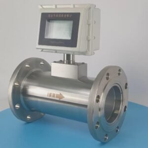
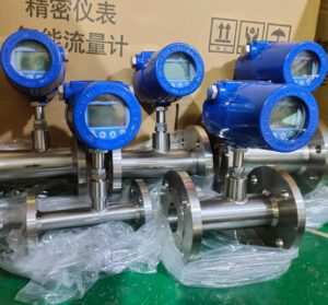
Thermal mass flow meters measure gas flow by detecting heat transfer from a sensor element to the flowing gas. They output a direct mass flow rate signal — in g/s, SLPM, SCCM, or kg/h depending on the model and configuration. Because thermal mass meters are calibrated for a specific gas composition, their output is accurate only when the actual gas matches the calibration gas. Changing the gas composition requires recalibration or a composition-correction factor — a workflow constraint that must be communicated clearly to customers switching between gas types. Jade Ant Instruments’ thermal mass flow meter guide covers gas-specific configuration requirements in detail.
Differential pressure (DP) meters — including orifice plates, Venturi tubes, and V-cones — measure volumetric flow and require a separate calculation to derive mass flow. The flow computer or PLC receiving the DP signal applies the flow equation:
Where is the discharge coefficient, A is the orifice area, ρ is fluid density at actual conditions, and ΔP is the measured differential pressure. Because ρ changes with temperature and pressure, DP meters used for mass flow measurement require real-time temperature and pressure inputs in addition to the DP signal. The unit of the mass flow output from the flow computer is a configured parameter — and it must match the DCS expectation.
Configuring Engineering Units in HART, Modbus, and FOUNDATION Fieldbus
HART protocol transmits the primary variable (flow rate) on the 4–20 mA loop and up to four variables digitally. Engineering unit configuration is performed through the device descriptor (DD) using a HART handheld communicator or HART-capable asset management software. In HART, the unit is a device parameter that must be explicitly set — the transmitter’s factory default is not necessarily the unit the DCS expects.
Modbus RTU/TCP maps each process variable to a specific register address. The engineering unit associated with that register is defined in the instrument’s function specification — not transmitted with the data. A Modbus register delivering “12345” means nothing without knowing whether that number represents kg/h, lbm/h, or SLPM. This unit-register mapping must be explicitly documented in the instrument’s configuration record and must be verified against the PLC’s input scaling block during commissioning.
FOUNDATION Fieldbus carries engineering units as part of the device data structure. The AI (Analog Input) function block transmits the measurement value with the associated unit code — a FOUNDATION Fieldbus unit code number that the DCS translates to a displayed unit string. If the unit code in the instrument does not match the unit expected by the DCS AI block, the DCS may display the measurement in a different unit than intended — a discrepancy that may not be visible from the operator station without specifically checking the AI block parameters.
| Protocol | Unit Configuration Method | Risk of Silent Unit Mismatch |
|---|---|---|
| 4–20 mA Analog | Not transmitted — set in DCS scaling only | High — DCS assumes unit from engineering |
| HART | Set in device via DD file; transmitted on request | Medium — must verify DD vs. DCS config |
| Modbus RTU/TCP | Register address + separate documentation | High — register value has no unit tag |
| FOUNDATION Fieldbus | Unit code in AI function block | Low — unit code transmitted with value |
| Profibus PA | Device profile parameter; checked in DCS | Medium — profile parameter must match |
8. Global Considerations: Regional Unit Preferences and Compliance Standards

For OEM manufacturers shipping skids to multiple global destinations, for distributors importing instruments from manufacturers in one region for sale in another, and for EPC firms executing projects across jurisdictions, unit selection is a compliance issue as much as a technical preference.
US vs. EU vs. Asia: A Practical Regional Map
North American markets — the United States, Canada, and Mexico — use predominantly imperial units (lbm/h, lbm/s, SCFM) in oil and gas, chemical, and power industries, driven by legacy infrastructure built under API and ASME standards. Metric units (kg/h, Nm³/h) appear in pharmaceutical, food processing, and newer manufacturing facilities. API MPMS governs custody transfer; ASME MFC governs DP measurement; NIST provides the primary measurement reference.
European markets — Germany, France, Netherlands, UK, and Scandinavia — operate uniformly in SI units (kg/h, Nm³/h, g/s). European gas measurement uses Nm³/h with Normal conditions at 0°C and 1.01325 bar per ISO 2533. Custody transfer instruments must comply with EU Measuring Instruments Directive (MID) and carry CE marking with the appropriate module letter. Instruments certified only under OIML or US NIST standards are not automatically accepted for EU trade measurement applications.
Asian markets vary by country and industry. Japan and South Korea use SI units almost exclusively in new installations. China uses SI units with GB (Guobiao national standard) references that generally align with ISO but with occasional differences in reference conditions for gas flow. India uses a mixed system — SI units in new petrochemical and pharmaceutical facilities, imperial units in older refineries and chemical plants built to British standards.
Middle Eastern markets — Saudi Arabia, UAE, Kuwait, and Qatar — use predominantly US units in oil and gas (driven by US licensors and US-built infrastructure) with SI units appearing in newer facilities and in any project delivered by European EPC firms.
Standards That Define Unit Requirements
ISO 5167 — the international standard for fluid flow measurement using orifice plates, nozzles, and Venturi tubes — specifies that flow rate shall be reported in m³/s or kg/s (SI units), with explicit conversion factors provided for conversion to other units. Instruments installed under ISO 5167 compliance must document results in SI units or with SI unit equivalents shown.
API MPMS (Manual of Petroleum Measurement Standards) — the governing standard for custody transfer in North American oil and gas — specifies measurement in barrels per day, gallons per minute, or SCFM for volumetric measurement, and in pounds per hour or tonnes per day for mass measurement, depending on the chapter. Chapter 5 (turbine meters), Chapter 6 (Coriolis meters), and Chapter 21 (electronic measurement) each specify unit requirements for compliant reporting.
ASME MFC-3M — governing DP measurement in US industrial applications — requires reporting in SI units (m³/s, kg/s) with imperial equivalents acceptable where documented. Instruments used in nuclear or safety-classified applications must additionally comply with ASME NQA-1 quality assurance requirements, which extend to calibration certificate format and unit traceability documentation.
Export Documentation and Customs Risk
A meter calibrated in kg/h shipped to a US facility whose instrument tagging system is in lbm/h creates a documentation mismatch that surfaces during regulatory inspection. The instrument tag says “lbm/h”; the calibration certificate says “kg/h”; the DCS is configured in lbm/h. An FDA auditor, an API inspector, or an EPA compliance reviewer who sees this three-way inconsistency will issue a finding — not because the measurement is wrong, but because the documentation trail cannot be reconciled without additional engineering evidence.
The corrective documentation — a unit equivalence certificate or a conversion statement signed by a registered professional engineer — costs between $500 and $2,000 in engineering time per instrument. Across a 50-instrument skid, that is $25,000 to $100,000 in avoidable documentation cost.
9. Troubleshooting Common Mass Flow Unit-Related Field Issues
Symptom Diagnosis Table
| Symptom Observed | Most Likely Root Cause | Diagnostic Check |
|---|---|---|
| Batch weights consistently 2.2× off target | kg/h instrument → lbm/h PLC (or reverse) | Check PLC scaling block engineering unit vs. instrument factory unit |
| Gas billing 6–7% high or low vs. expected | Nm³/h vs. Sm³/h reference condition mismatch | Verify T and P reference conditions in flow computer config |
| Flow reading drops precisely at pump start | SCFM vs. ACFM mismatch — reading actual, not corrected | Check if temperature and pressure compensation is active |
| Audit discrepancy: meter total ≠ batch record | HART unit transmitted differs from analog scaling | Read HART PV unit from device; compare to DCS tag engineering unit |
| PLC alarm trips at normal operating flow | Full-scale configured in wrong unit (kg/h set as lbm/h) | Check analog input range: 4 mA = 0, 20 mA = full scale in stated unit |
| Inconsistent readings between two identical meters | One meter at 0°C reference, one at 15°C reference | Check each instrument’s standard condition setting |
The 7-Step Commissioning Checklist for Unit Verification
This checklist is designed for commissioning engineers and instrument technicians who want to eliminate unit-related errors before a single process batch runs.
Confirm the required unit from the client’s DCS input configuration — not from the P&ID, not from the datasheet, from the actual DCS tag configuration (check the engineering unit parameter in the DCS I/O module).
Read the instrument’s configured output unit from the device itself using a HART communicator, Modbus register read, or the local operator interface. Compare it to Step 1.
Verify the reference condition for all gas measurement instruments — confirm that the T and P reference used in the instrument’s standard condition calculation matches the project standard condition assumption.
Check the PLC scaling block — confirm that the full-scale value in the analog input scaling (the value assigned to 20 mA) is in the same unit as the instrument’s output, and matches the process design maximum flow rate in that unit.
Run a zero-flow verification — with no flow, confirm the instrument outputs its configured zero value and the PLC reads zero in the expected unit. A non-zero zero indicates a configuration error or a reference condition problem.
Run a reference-flow test — inject a known flow (from a portable reference meter, a calibrated bypass, or a process condition where flow is independently verified) and compare the instrument reading to the reference in the same unit.
Document the verified configuration — record the confirmed unit, reference conditions, PLC scaling parameters, and calibration reference in the instrument loop folder. This record is the audit evidence that a correctly configured measurement system was delivered to the client.
10. Best Practices Across the Supply Chain: OEMs, Distributors, EPCs, and End Users
Aligning Specifications from RFQ to Commissioning
Unit consistency across the supply chain requires that every document in the instrument procurement chain — the RFQ (Request for Quotation), the purchase order, the instrument data sheet, the calibration certificate, and the FAT test procedure — specifies the same engineering unit for each measurement point, with no assumption that any party will perform a conversion.
The practical implementation is a unit specification block that appears in every document as a mandatory field:
Engineering Unit Required: kg/h | Reference Condition (if gas): 0°C, 1.01325 bar (Nm³/h convention) | Confirmed by (name and date):
This block takes 15 seconds to fill in and prevents the calibration certificate / DCS configuration mismatch that costs days of field rework.
Training Field Technicians Before Installation, Not After
The most expensive time to discover a unit error is during site commissioning, when the technician is at the instrument, the instrument is in the process line, and the production team is waiting. The cheapest time to discover it is before the instrument leaves the factory.
Instrument distributors serving OEM and EPC clients build measurable goodwill by providing brief pre-shipment unit verification reports — a one-page document confirming the shipped unit, the reference condition setting, and the HART or Modbus configuration record — with every instrument delivery. Clients who receive this document can verify unit alignment at their desk before the instrument reaches the site, eliminating the “we need to check this before we connect it” delay that generates field overtime costs.
Jade Ant Instruments provides calibration certificates with explicit unit statements and reference condition documentation for all mass flow instruments — a standard package that supports distributor partners in presenting a complete, audit-ready delivery to OEM and EPC clients.
Cross-Functional Review Before Design Freeze
Before finalizing an instrument specification package, a 30-minute cross-functional unit review involving the instrument engineer, the PLC/DCS programmer, and the commissioning team lead eliminates the majority of unit specification errors. The agenda for that review:
- Walk the instrument list and confirm the required engineering unit for every measurement point
- Verify that gas measurement reference conditions are consistent across all instruments in the package
- Confirm that the PLC scaling blocks have been written with the correct full-scale value in the confirmed unit
- Identify any instrument with a non-configurable factory unit that may require a flow computer for unit conversion
This review costs approximately 30 engineer-hours on a 50-instrument skid project. Industry data from commissioning audits consistently shows that the cost of field rework from unit errors averages 4–8 engineer-days per skid. The return on 30 minutes of pre-design review is unmistakable.
For additional technical guidance on flow meter selection and specification including unit configuration support, the Jade Ant Instruments how-to selection guide and the mass flow meter brand comparison resource provide structured frameworks for evaluating instrument options against unit, accuracy, and integration requirements.
Glossary of Key Terms
Mass Flow Rate (ṁ): The mass of fluid passing through a measurement point per unit of time, expressed as kg/h, lbm/h, g/s, etc. Unaffected by changes in fluid temperature or pressure, making it the preferred measurement for custody transfer, chemical dosing, and regulatory reporting.
Volumetric Flow Rate (Q): The volume of fluid passing through a measurement point per unit of time, expressed as m³/h, L/min, GPM, SCFM, etc. Changes with fluid temperature and pressure; requires density compensation to convert to mass flow.
Standard Conditions: A defined set of reference temperature and pressure used to normalize gas volumetric measurements. Allows comparison of gas quantities measured at different operating conditions. Common references: ISO/DIN (0°C, 1.01325 bar), US API (15.6°C / 60°F, 14.696 psia).
SCFM (Standard Cubic Feet per Minute): Volumetric gas flow rate corrected to US standard conditions (60°F, 14.696 psia). Widely used in North American oil and gas, compressed air, and gas processing applications.
Nm³/h (Normal Cubic Meters per Hour): Volumetric gas flow rate corrected to Normal conditions per ISO 2533 (0°C, 1.01325 bar). The standard unit for gas measurement in European industrial and energy applications.
lbm (Pound-Mass): A unit of mass equal to 0.45359 kg. The correct unit for mass flow rate in imperial systems. Not the same as lbf (pound-force) — the distinction matters in engineering documentation for aerospace, military, and calibration applications.
Coriolis Effect: The physical phenomenon causing a phase shift in vibrating tubes when mass flows through them. The basis of Coriolis flow meter measurement — provides direct mass flow without external density or temperature compensation.
K-Factor: In turbine and pulse-output meters, the number of pulses per unit volume delivered by the meter. Must be expressed in the same unit system as the PLC’s volumetric scaling to produce a correct flow rate calculation.
SCCM (Standard Cubic Centimeters per Minute): A gas volumetric flow unit at standard conditions used in semiconductor process gas supply, laboratory instruments, and pharmaceutical micro-dosing. Gas-specific: the mass flow equivalent depends on the molecular weight of the specific gas.
DCS (Distributed Control System): The central automation platform that receives measurement signals from field instruments and executes process control logic. Unit configuration in the DCS must match the instrument output unit — a mismatch produces a correct-looking but numerically wrong process variable.
Frequently Asked Questions (FAQs)
1. What is the difference between mass flow rate and volumetric flow rate?
Mass flow rate measures the actual mass of fluid — the quantity of matter — passing through a measurement point per unit of time (kg/h, lbm/h, g/s). It is independent of fluid temperature and pressure. Volumetric flow rate measures the volume of fluid passing through a point per unit of time (m³/h, L/min, SCFM). Volume changes with temperature and pressure, so two volumetric flow readings taken at different operating conditions may represent very different quantities of fluid, even if the numbers look similar. For any application where the physical or financial value of the fluid is based on mass — chemical reactions, custody transfer, pharmaceutical batch records, emissions monitoring — mass flow rate is the only defensible measurement basis.
2. Why is mass flow rate more accurate than volumetric flow for gases?
Gases are compressible: their volume changes significantly with temperature and pressure. A gas at 8 bar and 80°C occupies approximately one-tenth the volume it would at atmospheric conditions. A volumetric meter that does not apply pressure and temperature correction produces a reading that varies with every pressure or temperature fluctuation in the line — even when the actual mass flow rate is constant. A mass flow meter, or a correctly compensated volumetric meter with a flow computer, corrects for these variations and delivers a reading that represents the true quantity of gas, regardless of operating conditions. For more on gas flow measurement accuracy by technology type, see Sage Metering: Gas Mass Flow Rate Units of Measure.
3. How do I convert SCFM to kg/h for natural gas?
The conversion requires two steps: first convert SCFM to Sm³/h (multiply by 1.699), then multiply by the gas density at standard conditions. For natural gas (approximately 95% methane, MW ≈ 16.4 g/mol) at US standard conditions (15.6°C, 1 atm), density ≈ 0.678 kg/m³. So: kg/h = SCFM × 1.699 × 0.678 = SCFM × 1.152. For 500 SCFM of natural gas: 500 × 1.152 = 576 kg/h. For different gas compositions, replace 0.678 with the correct density for that gas at standard conditions. Always confirm whether “standard conditions” means 60°F (US convention) or 0°C (European/ISO convention) before applying gas density values.
4. What does “standard” mean in Standard Cubic Feet per Minute (SCFM)?
It means that the volumetric reading has been mathematically corrected to a defined reference temperature and pressure — most commonly 60°F (15.6°C) and 14.696 psia (1 atmosphere) in US convention. The word “standard” does not mean there is a single universal standard: the EU uses 0°C and 1.01325 bar as “Normal” conditions for Nm³/h. The same mass of gas measured as 100 SCFM at US conditions reads as approximately 94 Nm³/h at EU Normal conditions — because the US reference temperature is warmer, causing the gas to occupy more volume at reference. Always confirm which “standard” is being used before comparing SCFM and Nm³/h values.
5. Can I directly compare lb/h and kg/h without conversion?
No. They are different units of mass per unit time. The conversion factor is 1 kg/h = 2.20462 lbm/h. For custody transfer and formal documentation, always use the full precision factor (2.20462), not the approximation (2.2). A 0.21% error from using the approximation on a custody transfer application handling $2 million per day of product equals $4,200/day in billing inaccuracy. For process monitoring where 1% accuracy is sufficient, the approximation is harmless — but using it in calibration certificates or legal documents is a professional risk.
6. Do Coriolis meters measure mass flow directly?
Yes. Coriolis meters measure mass flow through the physics of the Coriolis effect — fluid moving through vibrating tubes causes a measurable phase shift that is directly proportional to mass flow rate, regardless of fluid density, temperature, or pressure. No external density compensation, temperature correction, or pressure correction is required. The meter outputs mass flow in the configured engineering unit (kg/h, lbm/h, g/s, t/h) as a primary variable. It simultaneously measures fluid density and temperature, which are available as secondary HART variables or Modbus registers. This makes Coriolis the reference standard for direct mass flow measurement in applications ranging from pharmaceutical ingredient dosing to petroleum custody transfer. For a full review of Coriolis capabilities by model and manufacturer, see the Jade Ant Instruments Coriolis flow meter maintenance and calibration guide.
7. How do temperature and pressure affect mass flow readings?
They don’t — in a correctly operating mass flow meter. True mass flow rate is a physical quantity independent of temperature and pressure. A Coriolis meter, a thermal mass meter, or a correctly compensated DP meter with a flow computer reports the same mass flow rate regardless of operating temperature and pressure fluctuations. Where temperature and pressure do affect mass flow readings is through instrument calibration errors: a Coriolis meter whose zero is not correctly established at operating conditions will report a non-zero flow when no flow is present — a zero-shift error that appears as a temperature effect in practice. Similarly, a thermal mass meter calibrated at 25°C and deployed at 80°C without a temperature correction factor will have reduced accuracy. The meter physics are correct; the calibration reference must match the operating conditions.
8. What unit should I use for custody transfer of compressed gas?
Custody transfer of compressed gas is typically expressed in mass units — kg or lbm totalized over the measurement period — with the measurement reference documented to a national standard (NIST in the US, PTB in Germany, NMi in the Netherlands). Alternatively, it is expressed in energy units (MJ, BTU, or kWh) using the measured mass combined with a certified calorific value. Volumetric units (SCFM, Nm³/h) can be used for custody transfer if the standard conditions are explicitly documented in the contract and both parties use the same conditions for comparison. For compressed natural gas, the standard reference is the API MPMS custody transfer framework, which specifies measurement conditions, meter certification requirements, and proving frequency.
9. Why do my flow meters show different readings even if they are in the same line?
The most common cause is a unit or reference condition mismatch. If one meter is configured to output in kg/h and the second in lbm/h, and both readings are displayed on the same SCADA screen without unit labels, the operator sees two different numbers and assumes measurement error. A second common cause is different standard condition assumptions: one meter using 0°C reference and another using 15.6°C reference for the same gas measurement will produce readings that differ by approximately 5.7%. A third cause is different flow profile averaging: a single-path meter and a multi-path meter installed close together in the same line may see slightly different flow profiles. Before assuming hardware failure, verify that both instruments are configured to the same engineering unit and the same reference condition. For a structured troubleshooting approach, see Jade Ant Instruments: Common Flowmeter Mistakes That Cost Distributors Money.
10. How can I ensure unit consistency across multiple vendors in an EPC project?
The most effective tool is a Project Measurement Standard document — a controlled document issued by the EPC’s instrumentation lead at project inception — that specifies: the required engineering unit for every measurement category (liquid mass flow, gas mass flow, steam mass flow, etc.), the standard reference conditions for all gas measurements, the PLC/DCS engineering unit convention for every protocol (Modbus, HART, FOUNDATION Fieldbus), and the calibration certificate format required from all suppliers including the unit in which calibration was performed. This document is referenced in all instrument requisitions and is a mandatory input to the pre-commissioning loop check procedure. Vendors who deliver instruments not conforming to the Project Measurement Standard are flagged before the instruments reach site, not after they are installed. For integration and protocol guidance supporting this approach, see Turbines Incorporated: Flow Meter Communication Protocols Explained.
11. Is Nm³/h a mass or volumetric unit?
Nm³/h is technically a volumetric unit — Normal Cubic Meters per Hour — but because it is referenced to fixed Normal conditions (0°C and 1.01325 bar per ISO/DIN standard), it represents a fixed quantity of gas molecules and behaves functionally as a mass unit. For a given pure gas at known composition, Nm³/h can be converted directly to kg/h by multiplying by the gas density at Normal conditions. For mixed gases or gas compositions that change over time, the conversion requires knowing the current molecular weight or density. The practical distinction: treat Nm³/h as mass-equivalent for billing and process control purposes, but always document the reference conditions explicitly in contracts and calibration records. The definitive explanation of m³/h vs. Nm³/h vs. Sm³/h is at Silver Instruments: The Ultimate Guide to Gas Flow Rate Units.
12. What should I do if my PLC is displaying incorrect mass flow values?
Follow a structured four-step diagnostic: (1) Check the instrument’s configured output unit using a HART communicator or Modbus read — confirm what unit the instrument is actually transmitting. (2) Check the PLC input scaling block — verify that the full-scale engineering value assigned to 20 mA matches the instrument’s actual full-scale in the correct unit. A Coriolis meter with 1,000 kg/h full scale whose PLC block is scaled to 1,000 lbm/h produces a reading that is 2.2× too low. (3) For gas measurements, check the reference condition — confirm that the instrument’s standard condition setting matches the project standard. (4) Verify the Modbus or HART unit mapping — for digital protocols, check that the unit assigned to the register or process variable matches the DCS expectation, using the instrument’s function specification as the reference document. In most cases, one of these four checks will identify the error. If all four check out and the reading is still wrong, the problem is likely calibration-related rather than unit-related.
This guide is written for OEM skid-mount manufacturers, instrument distributors and importers, EPC system integrators, industrial MRO teams, and municipal utilities who need to get mass flow rate units right the first time — from specification through commissioning and into long-term operation.
For application-specific guidance on selecting and configuring mass flow meters across Coriolis, thermal, and differential pressure technologies, visit Jade Ant Instruments or explore the flow meter technology comparison guide for your specific application.