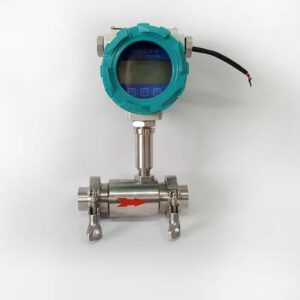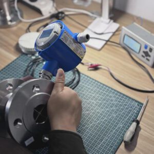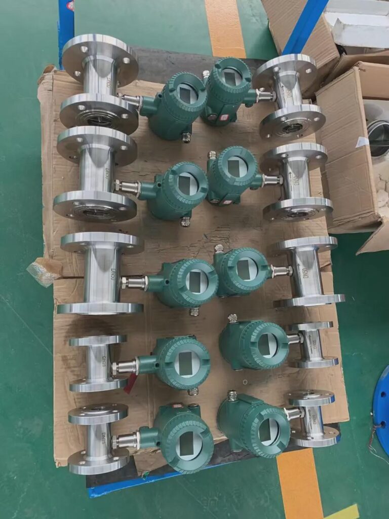

A stainless steel turbine flow meter integrated into an industrial skid system — compact, accurate, and built for clean liquid service.
Executive Summary
Every distributor has been in this situation: a client calls with a broken flow meter, a missed batch target, or a billing dispute with their water authority — and the root cause traces back to the wrong meter for the job. Not a defective meter. The wrong one.
Turbine flow meters have earned a permanent place in industrial measurement because they do specific jobs exceptionally well: measuring clean, low-viscosity liquids and gases with accuracy that touches ±0.25% of reading, responding to flow changes in milliseconds, and fitting into tight spaces that larger technologies simply cannot. A petroleum loading terminal in Rotterdam, a pharmaceutical plant batching purified water, a municipal treated-water distribution main — these are environments where turbine meters are not just a reasonable choice, but the technically correct one.
The global flow meter market was valued at USD 12.14 billion in 2026 and is projected to grow to USD 17.86 billion by 2033 at a 5.8% CAGR (Grand View Research). Within that market, turbine meters occupy a well-defined, high-value niche — and the turbine flowmeter segment alone was valued at USD 2.50 billion in 2025 (Verified Market Research). That’s not a shrinking technology. That’s a mature, stable, profitable segment with predictable replacement cycles and identifiable end-user demand.
This guide is written for the people who sell, specify, and support turbine flow meters in the field: instrument distributors and importers, OEM skid-mount manufacturers, EPC and system integrators, industrial terminal and MRO companies, and municipal and utility operators. It covers the working principles behind turbine meters, where they genuinely outperform alternatives, how to build a selection decision framework, what the real total cost of ownership looks like over ten years, and how to troubleshoot the most common field failures without sending the meter back to the factory.
If you’ve been defaulting to electromagnetic or ultrasonic meters because they’re easier to sell, this guide will give you the confidence to add turbine meters where they belong — and the language to explain why.
Understanding Turbine Flow Meters: Core Principles and Working Mechanism
How the Measurement Actually Works
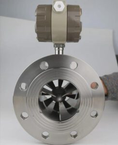
A turbine flow meter places a multi-bladed rotor directly in the flow path, supported on precision bearings inside the meter body. As fluid flows through the pipe, it strikes the angled rotor blades and causes the rotor to spin. The faster the fluid moves, the faster the rotor spins. That relationship — rotor speed proportional to fluid velocity — is the foundation of the entire measurement.
A magnetic pickup coil or Hall-effect sensor mounted outside the flow tube detects each rotor blade as it passes. Each blade passage generates one electrical pulse. The stream of pulses is converted to volumetric flow rate using a K-factor (explained below).
K-Factor (first-use definition): The number of electrical pulses the meter generates per unit volume of fluid — for example, 1,000 pulses per liter. It is determined during factory calibration and stamped on the meter’s data plate. Every time your client’s totalizer divides the incoming pulse count by the K-factor, it calculates exactly how much fluid has passed.
The K-factor is remarkably stable in a well-maintained turbine meter operating within its designed fluid conditions. Turbines Incorporated documents K-factor linearity within ±0.25% over a 10:1 turndown on clean hydrocarbons at stable viscosity — which is why turbine meters remain the standard for petroleum custody transfer.
What Makes Turbine Meters Different from Positive Displacement and Ultrasonic Alternatives
A positive displacement (PD) meter traps discrete volumes of fluid in compartments and counts them — highly accurate, but slow and prone to wear from abrasive particles. A clamp-on ultrasonic meter measures acoustic transit-time through the pipe wall — no contact, no pressure drop, but limited by pipe coating and slow response. A turbine meter sits between these extremes: it has moving parts (higher wear risk than ultrasonic), but it operates at much higher speeds than PD meters, responding to flow changes in milliseconds — a critical advantage in batching and dosing applications.
The linear relationship between rotor speed and flow rate also gives turbine meters an inherently clean, easy-to-integrate pulse output that connects directly to PLCs and batch controllers without signal conditioning.
Key Advantages for Your Clients: Why Turbine Meters Stand Out
The commercial case for turbine meters rests on four quantifiable performance attributes that translate directly into client value.
High accuracy on clean liquids. Under optimal conditions — clean fluid, viscosity below 10 centistokes (cSt), flow within the calibrated range — turbine meters achieve ±0.25% to ±0.5% of reading accuracy. Premium custody-transfer models reach ±0.1% (Sino Instruments, high-accuracy turbine guide). That level of precision directly protects against commercial discrepancies in petroleum metering and regulatory non-compliance in pharmaceutical batch records.
Turndown ratios of 10:1 to 20:1. Most flow meters perform well at rated flow but struggle at low-flow conditions. Turbine meters maintain their accuracy specification across a flow range that is 10 to 20 times wider than the minimum flow — a critical feature for fuel distribution terminals that serve everything from small vehicles to large tanker trucks through the same meter.
Millisecond response time. A turbine meter’s pulse output tracks instantaneous flow changes as fast as the rotor can respond. For batching systems where a target volume is set and a valve closes on reaching it, that fast response prevents overfill — each missed millisecond represents real product loss or measurement error. No ultrasonic or Coriolis meter matches this response speed at comparable price.
Compact form factor. A DN50 (2-inch) turbine meter body is typically 3 to 5 pipe diameters long. The equivalent Coriolis meter at the same size is larger, heavier, and more expensive to install. For OEM skid builders where every cubic centimeter of cabinet space is a design constraint, this compactness is not a minor convenience — it can determine whether a design works at all.
Cost-effective entry point. Standard sizes from DN15 to DN150 are available from $300 to $2,500 for process-grade meters, with custody-transfer units reaching $5,000. For multi-point installations — fuel farms, water distribution networks, or chemical plants with dozens of measurement points — turbine meters deliver acceptable accuracy at a unit cost that alternatives cannot match.
Application Suitability: Matching Meters to Industries and Fluids

Flanged turbine flow meter connections on a petroleum terminal fuel loading rack — one of the turbine meter’s strongest application environments.
Turbine meters are genuinely excellent in the right conditions and genuinely wrong in others. The following breakdown maps the technology to its strongest industry applications and flags where client conversations should redirect to alternatives.
Oil and Gas: Custody Transfer and Fuel Distribution
Petroleum measurement is the turbine meter’s home territory. The API Manual of Petroleum Measurement Standards (MPMS) Chapter 5.3 explicitly recognizes turbine meters for fiscal metering of refined petroleum products. At a fuel loading terminal, the meter’s pulse output directly drives batch controllers that close loading valves at preset volumes — and its ±0.25% accuracy protects both the terminal operator and the truck driver from commercial disputes.
A Gulf Coast fuel terminal processing 50,000 barrels per day through 12 turbine meters operates with a combined measurement uncertainty of 0.15%, verified by prover runs every 30 days. At $80/barrel, a 0.1% improvement in measurement uncertainty represents $40,000 per day in protected commercial value.
Fluid prerequisite: Diesel, gasoline, JET-A1, and LPG are ideal — clean, relatively low viscosity, no solids. Crude oil with paraffin deposits or water contamination is not suitable without upstream conditioning.
Water and Wastewater: Treated Water Distribution
In treated, filtered municipal water systems, turbine meters offer lower installed cost than electromagnetic alternatives while meeting the accuracy requirements of distribution metering. Badger Meter turbine units cover DN13 (½-inch) through DN300 (12-inch) at ±1.0% accuracy — sufficient for billing and non-revenue water (NRW) auditing in treated distribution mains.
The critical qualifier here is treated water only. Raw water with sand, grit, or biological matter will destroy turbine bearings within months. For raw water, pumping stations, or wastewater streams, electromagnetic meters are the correct technology.
Chemical Processing: Solvents and Low-Viscosity Additives
Low-viscosity solvents — ethanol, acetone, methanol, light acids diluted below 20% concentration, de-ionized water — are excellent turbine meter candidates in pharmaceutical manufacturing and chemical blending. The pulse output integrates directly into PLC batch controllers for precise volumetric totalizing. Sanitary versions with tri-clamp connections and 3-A certification are available for food-grade and pharmaceutical applications.
The viscosity limit is hard: above approximately 50 to 100 cSt, the bearing drag shifts the K-factor and accuracy degrades significantly. For heavy oils, glycols at low temperature, or polymer solutions, Coriolis or positive-displacement meters are more appropriate.
Power Generation: Cooling Water and Fuel Oil
Cooling water in closed-loop treatment systems (not raw river or pond water), light fuel oil for burner control, and condensate return metering are all well-suited to turbine meters. Power plant fuel oil is typically heated to reduce viscosity below the turbine meter threshold before measurement — a standard practice in heavy fuel oil installations.
OEM Skid Systems: Packaged Unit Integration
For OEM manufacturers building packaged systems — chemical dosing skids, water treatment units, fuel blending packages, or hydraulic power units — turbine meters offer the critical combination of compact size, direct pulse output, and mid-range cost that fits standard skid budgets. Jade Ant Instruments supports OEM applications with non-standard pipe sizes, customized output signals, and ODM configurations that keep the turbine meter invisible behind the OEM brand while delivering measurement performance the end user can rely on.
Critical Selection Criteria for Distributors
The following table provides the core selection framework your team should work through before recommending a turbine meter — or redirecting to an alternative.
| Selection Parameter | Acceptable Range / Requirement | Red Flag: Redirect to Alternative |
|---|---|---|
| Fluid type | Clean liquids and gases; no suspended solids | Slurries, raw sewage, fibrous media → use electromagnetic |
| Viscosity | < 50 cSt preferred; up to ~100 cSt max | > 100 cSt → use Coriolis or PD meter |
| Fluid conductivity | Not required (unlike electromagnetic) | N/A |
| Flow velocity | 0.3 m/s minimum; 0.5–3 m/s optimal; 6–10 m/s max | Below 0.3 m/s → signal unreliable |
| Pipe size | DN6 to DN600 (varies by manufacturer) | DN600+ → consider insertion ultrasonic |
| Temperature | –40°C to +200°C (standard); up to +250°C (high-temp models) | > 250°C → use vortex meter |
| Pressure | Up to 420 bar for custody-transfer designs | No restriction for turbine; check flange rating |
| Accuracy requirement | ±0.25%–±1.0% (volumetric, clean liquid) | ±0.05% mass flow → use Coriolis |
| Fluid cleanliness | 25–75 micron filtration upstream required | Dirty service without filtration → bearing failure in months |
| Output signal | Pulse, 4–20 mA, HART available | PROFIBUS, FOUNDATION Fieldbus → verify transmitter model |
| Approvals needed | FM, ATEX/IECEx (hazardous area); SIL (safety); MID (EU billing); NSF (food/pharma) | Confirm before specifying |
| Bidirectional flow? | Some models support; requires dual-channel transmitter | Unidirectional only in standard models |
For a comprehensive five-factor engineering selection process covering performance, fluid properties, installation, environment, and lifecycle cost, the Jade Ant Instruments flow meter selection guide provides a structured framework applicable to turbine and all competing technologies.
Total Cost of Ownership: Beyond the Initial Price Tag
Turbine meters are often sold on unit price, and that framing does clients a disservice. The real question is not “how much does the meter cost?” but “how much does accurate flow measurement cost per year over the equipment’s service life?”
According to Turbines Incorporated’s TCO analysis, a turbine meter that costs $4,000 and lasts 15 years comes to $267 per year in amortized capital cost. That is lower than most competing technologies at the same pipe size when viewed purely as a capital expenditure. The variable is maintenance — and maintenance cost is almost entirely a function of how clean the upstream fluid is.
The following table presents a 10-year TCO comparison for a DN50 (2-inch) clean liquid application at a mid-value fluid throughput of $200,000 per year.
| Cost Category | Turbine Meter | Electromagnetic Meter | Coriolis Meter |
|---|---|---|---|
| Capital purchase (DN50) | $1,500–$2,500 | $1,800–$3,000 | $7,000–$12,000 |
| Installation labor + fittings | $800–$1,200 | $1,000–$1,500 | $1,200–$2,000 |
| Calibration events (10 years) | 5–7 events × $200–$400 | 3–5 events × $250–$400 | 1–2 events × $800–$1,200 |
| Bearing replacement (4 events) | $600–$1,600 | $0 (no bearings) | $0 (no bearings) |
| Upstream strainer maintenance | $400–$800 | $0 | $0 |
| Process downtime (maintenance) | $2,000–$4,000 | $500–$1,000 | $200–$500 |
| Product loss (measurement error) | $3,000–$6,000* | $1,000–$2,000* | $200–$400* |
| 10-Year TCO (estimated) | $12,000–$22,000 | $8,000–$14,000 | $11,500–$19,500 |
Product loss estimate based on accuracy drift over service life applied to $200,000/year fluid throughput. Source: Jade Ant Instruments application engineering data, synthesized from 2024–2025 field cases; flowmeters.co.uk TCO analysis.
The takeaway is clear: turbine meters offer the lowest entry cost and are competitive over 10 years in clean liquid service with disciplined maintenance. Their TCO disadvantage emerges in moderate-to-dirty service where bearing replacement and calibration frequency accelerate. For your clients in petroleum, treated water, and pharmaceutical clean-utility streams, turbine meters remain genuinely cost-effective. For clients in raw water, wastewater, or chemical slurry service, the electromagnetic meter’s lower 10-year TCO makes the case for switching even at a higher purchase price.
When you present this table to a client — filled in with their own labor rates and fluid values — the technology selection conversation stops being about unit price and starts being about total operational cost.
Integration and Installation Best Practices

Proper straight-pipe run maintained upstream of a turbine flow meter in a pharmaceutical clean-utility installation — a non-negotiable installation requirement.
Turbine meters are sensitive to the velocity profile of the fluid arriving at the rotor. A disturbed, asymmetric velocity profile — caused by an elbow, valve, reducer, or pump too close upstream — will cause the rotor to spin unevenly, degrading accuracy and accelerating bearing wear. The following installation guidelines apply across most turbine meter designs.
Straight-pipe run requirements are the most commonly violated installation parameter. The minimum for most turbine meters is 10 to 20 pipe diameters (D) upstream and 5D downstream of undisturbed, straight pipe. After a 90° elbow: 20D upstream minimum. After a control valve: 30D upstream. After a pump outlet: verify with the manufacturer — some installations require flow conditioners.
Flow conditioner (definition): A device installed in the pipe upstream of the meter that breaks up swirl and redistributes velocity across the pipe cross-section. A good conditioner can reduce the upstream straight-run requirement from 20D to approximately 10D. Cost: $500–$2,000 depending on size.
For a complete installation checklist covering piping, wiring, commissioning procedures, and the seven costliest installation mistakes, the Jade Ant Instruments flow meter installation guide provides step-by-step guidance applicable to turbine and most other meter technologies.
Orientation affects bearing load. Horizontal installation with the shaft horizontal (flow running through the horizontal axis) is standard. Vertical installation with upward flow is acceptable. Vertical downward flow is generally not recommended — gravity loads the bearing asymmetrically. Confirm with the specific manufacturer.
Vibration sensitivity is a real concern in pumping stations and compressor houses. Mechanical vibration can induce false pulses in the pickup coil. Install vibration-isolation mounts where vibration levels exceed 0.5g, and ensure the meter body is not mechanically coupled to vibrating equipment through rigid pipe runs.
Grounding and shielding for pulse output. The pulse signal from a turbine meter pickup coil is a low-level, high-frequency signal (up to several kHz). Run the signal cable in a separate conduit from power cables. Use shielded twisted-pair cable and ground the shield at one end only — at the receiving instrument — to avoid ground loops that introduce noise into the pulse count.
Upstream filtration. Specify a 25- to 75-micron strainer immediately upstream of every turbine meter in liquid service. This is not optional; it is the primary factor controlling bearing life. A fuel terminal in Rotterdam documented a 0.3% K-factor shift after 14 months of operation on a diesel line that exceeded the 25-micron specification — a finding that triggered bearing replacement across 40 meters at an unplanned cost of $18,000 in a single maintenance event.
Calibration, Certification, and Traceability
A turbine meter leaves the factory with a known K-factor. Over time, bearing wear increases rotor drag, the K-factor drifts, and the meter under-registers — often imperceptibly. By the time a client notices a discrepancy, the measurement has been inaccurate for months.
Regular calibration catches drift before it becomes a commercial or compliance problem.
NIST-traceable calibration means the calibration laboratory’s reference standards have been verified against national measurement standards maintained by the National Institute of Standards and Technology (or equivalent national metrology body). For your clients in petroleum billing, pharmaceutical manufacturing, or municipal water billing, calibration certificates that are not NIST-traceable (or equivalent: UKAS, PTB, NMi) are not accepted by auditors or regulatory bodies.
Calibration interval depends on application severity. The following guidelines represent industry best practice:
- Petroleum custody transfer (fiscal metering): Every 6–12 months; prover verification more frequently depending on throughput and regulatory requirements under API MPMS.
- Municipal water billing: Every 12 months per most national water regulations; some jurisdictions require 6-month intervals for large revenue meters.
- Pharmaceutical clean utilities: Every 12 months minimum; aligns with instrument qualification (IQ/OQ/PQ) cycles under FDA 21 CFR Part 211.
- General process control: Every 24 months if fluid conditions are stable and the transmitter diagnostics show no K-factor drift.
In-house versus third-party calibration. Distributors who offer NIST-traceable calibration services as a bundled offering with turbine meter sales create a recurring revenue stream and a client retention mechanism. A client who relies on you for annual calibration of 20 meters does not quietly switch suppliers between calibration visits. For practical guidance on on-site calibration using clamp-on ultrasonic reference meters to verify installed turbine meters — a common practice in petroleum and water utility applications — the Emerson on-site calibration overview provides a useful technical reference.
Turbine Flow Meter Technology — Visual Overview
The video below provides a clear, manufacturer-neutral explanation of turbine flow meter operating principles, K-factor calibration, and application selection — useful for distributor team training and client pre-sales conversations.

▶ Watch: Technology and Working Principle of Turbine Flowmeters — covers rotor design, K-factor, accuracy, and application selection.
Troubleshooting Common Field Issues
Your clients will call with flow meter problems before they call with purchase orders. The distributor who can diagnose the root cause quickly — without sending the meter to a service depot — builds a level of trust that no pricing strategy can replicate.
The following quick-reference table covers the five most common turbine meter field failures, their causes, and the corrective actions your technical team should work through first.
| Symptom | Probable Cause(s) | Diagnostic Step | Corrective Action |
|---|---|---|---|
| No output signal | Debris jamming rotor; sensor gap too large; broken signal cable | Inspect rotor visually (remove meter if accessible); check cable continuity with multimeter; check sensor gap (typical: 0.5–1.5 mm) | Clear obstruction; adjust sensor gap per manufacturer spec; replace cable |
| Low or unstable signal | Partially blocked rotor; bearing wear; air in the line; flow below minimum | Check transmitter frequency display at known flow rate; listen for rotor noise; check for air pockets | Flush system to remove air; clean strainer; replace bearings if worn |
| Output reads high (over-registration) | Air entrainment giving fluid a lower density than calibrated; K-factor programmed incorrectly | Check for aeration upstream (pump cavitation, valve cavitation); verify K-factor in transmitter programming | Eliminate air source; reprogram K-factor from calibration certificate |
| Output reads low (under-registration) | Bearing wear (most common); viscosity higher than at calibration; rotor blade damage | Compare current frequency at known flow to historical baseline; measure fluid viscosity at operating temperature | Replace bearing kit ($150–$400); recalibrate at operating viscosity; inspect and replace rotor if blade damaged |
| Drifting output (readings change over time) | Progressive bearing wear; fluid contamination affecting viscosity; magnetic pickup coil weakening | Trend flow readings versus independent reference; pull meter for inspection and calibration | Bearing replacement + recalibration; upgrade to ceramic bearings for longer intervals in aggressive service |
| K-factor shift confirmed at recalibration | Bearing wear; rotor erosion; foreign material on blades; viscosity change | Inspect rotor under magnification for pitting, erosion, or deposits | Clean or replace rotor assembly; recalibrate; investigate upstream filtration adequacy |
K-factor drift insight: According to Turbines Incorporated’s engineering data, bearing wear is the primary long-term cause of K-factor drift — increasing bearing friction causes the rotor to spin slightly slower than the true flow velocity, leading to systematic under-registration. A 0.5% K-factor shift on a pipeline transferring $10 million of product annually represents $50,000 in unaccounted product. This is why scheduled bearing inspection and calibration are not optional costs — they are loss-prevention measures.
Partnering for Success: How We Support Your Business
Jade Ant Instruments is designed from the ground up to support the business model of instrument distributors, not to compete with it. The value proposition goes beyond the meter specification sheet.
Technical pre-sales support. When your client has an unusual application — a fluid at the edge of the viscosity range, a pipe size outside standard catalog options, a hazardous-area classification that requires specific approvals — the Jade Ant engineering team provides specification support before the order is placed. Getting the specification right the first time eliminates returns, saves your credibility, and keeps your client’s project on schedule.
OEM and skid-mount customization. For OEM equipment manufacturers integrating turbine meters into packaged systems, Jade Ant Instruments provides non-standard configurations: custom end fittings, white-label transmitters, modified output signal ranges, and extended temperature options. The OEM receives a meter that fits the skid design, the end user sees the OEM brand, and the underlying performance delivers on the specification.
Bulk pricing for distributors. Volume-based pricing tiers are available for established distributor partners. Stocking agreements reduce lead times for your clients’ scheduled maintenance replacements and emergency sourcing requirements — a practical advantage when a client’s fuel terminal is down at 2 AM waiting for a bearing kit.
Field training. Application-focused training sessions — covering installation requirements, K-factor programming, calibration procedures, and troubleshooting — are available for distributor sales and technical teams. A trained sales team closes more applications and generates fewer costly post-installation support calls.
After-sales technical support. A dedicated application engineering contact, not a general helpdesk queue, handles distributor technical questions. If your client has a problem in the field, you have someone to call who knows the product.
For the full range of turbine and gas/steam flow meter models available for distributor partnering, the Jade Ant Gas and Steam Turbine Flow Meter product page and the distributor product portfolio overview provide detailed specifications and configuration options.
Turbine vs. Alternative Technologies: When to Recommend Each

Multi-technology flow measurement installations — knowing which meter type to recommend in each application is the distributor’s most valuable technical skill.
| Application | Recommend Turbine? | Better Alternative | Reason |
|---|---|---|---|
| Petroleum custody transfer (diesel, gasoline, JET-A1) | ✅ Yes | — | ±0.25% accuracy, API MPMS compliant, fast pulse output |
| Clean potable water distribution metering | ✅ Yes | Electromagnetic (if budget allows) | Low cost, proven, adequate accuracy for billing |
| Aviation fuel loading | ✅ Yes | — | Compact, fast response, Weights & Measures certified |
| Raw or lightly treated water | ❌ No | Electromagnetic | Solids damage bearings within months |
| Municipal wastewater and sewage | ❌ No | Electromagnetic | Solids, fibrous material, and biological matter destroy rotors |
| Steam measurement | ❌ No | Vortex | Turbine meters are not designed for steam service |
| Compressed air or natural gas | ✅ Conditional | Vortex or thermal mass | Gas-specific turbine models only; not liquid meters |
| High-viscosity oils (>100 cSt) | ❌ No | Coriolis or PD meter | Viscosity loads bearings and shifts K-factor |
| Chemical slurries | ❌ No | Electromagnetic or Coriolis | Abrasive particles destroy rotor and bearings |
| Pharmaceutical clean utilities (PW, DI water) | ✅ Yes (sanitary model) | Coriolis (if mass measurement needed) | Sanitary turbine with 3-A certification meets requirements |
| Batch dosing of low-viscosity solvents | ✅ Yes | Coriolis (higher accuracy) | Pulse output integrates directly with batch PLCs |
For a full cross-technology comparison covering ultrasonic, electromagnetic, and turbine meters across 12 application parameters, the Jade Ant Instruments ultrasonic vs. magnetic vs. turbine comparison guide provides a side-by-side reference your sales team can use in client conversations.
Quick Glossary of Turbine Flow Meter Terms
These definitions appear throughout the article. Bookmark this section for quick client-facing reference.
K-Factor: The number of pulses the meter outputs per unit volume (e.g., pulses/liter). Determined at factory calibration; stored in the transmitter.
Turndown ratio: The ratio of maximum to minimum measurable flow within the stated accuracy specification. A 10:1 turndown on a meter rated at 100 L/min means it measures accurately down to 10 L/min.
cSt (centistokes): Unit of kinematic viscosity — how resistant a fluid is to flow. Water at 20°C is approximately 1 cSt; motor oil is 100–300 cSt. Turbine meters are suited to fluids below 50–100 cSt.
NIST-traceable calibration: Calibration verified against national measurement standards, creating an unbroken chain of comparison back to SI units. Required for fiscal, billing, and regulatory applications.
ATEX certification: European certification confirming equipment is safe for use in potentially explosive atmospheres (from the French: ATmosphères EXplosibles). Required in Class I Div 1/2 equivalent environments across the EU.
Hall-effect sensor: An electronic sensor that detects magnetic field changes — used in turbine meters to detect each rotor blade passage without physically contacting the rotor.
Flow conditioner: A device placed upstream of the meter that normalizes the velocity profile across the pipe cross-section, reducing the required straight-pipe run length.
Custody transfer: The commercial transaction point where ownership of a fluid transfers between parties. Flow measurement at custody transfer points is legally binding and subject to certified accuracy requirements.
Frequently Asked Questions
1. What is the typical accuracy of a turbine flow meter?
Most industrial turbine meters achieve ±0.5% of reading under optimal conditions — clean fluid, viscosity below 10 cSt, flow within 20–80% of rated maximum. Premium custody-transfer models, calibrated on-site with NIST-traceable references, reach ±0.1% to ±0.25%. Accuracy degrades as viscosity rises or as bearing wear accumulates, which is why calibration intervals and upstream filtration are not optional for accuracy-critical applications.
2. Can turbine flow meters measure viscous fluids like heavy oil or glycol?
Turbine meters perform best with fluids below 50 cSt and can handle up to approximately 100 cSt with a viscosity-matched calibration. Above 100 cSt, bearing drag becomes significant enough to cause systematic under-registration — the rotor spins slower than the fluid velocity. For heavy fuel oil, glycols at low temperature, or polymer solutions, Coriolis meters (for mass measurement) or positive-displacement meters (for volumetric custody transfer) are the technically correct alternatives. Attempting to run a turbine meter outside its viscosity range is one of the top three causes of unexplained measurement discrepancies in industrial installations.
3. Are turbine flow meters suitable for hazardous area installations?
Yes. Turbine meters with FM (Factory Mutual), ATEX, or IECEx approvals are available for Class I Division 1/2 and Zone 0/1/2 hazardous atmospheres. Intrinsically safe configurations use barriers or Zener diode isolators to limit the energy in the signal circuit below the ignition threshold for the classified gas group. For applications requiring SIL (Safety Integrity Level) certification — safety-critical shutdown systems in chemical plants or offshore platforms — SIL-rated transmitter models are available. Always verify the specific approval markings against the area classification before specifying. For a reference guide to ATEX-certified flow meter selection, the Jade Ant Instruments hazardous area flow meter guide covers the key approval requirements across FM, ATEX, and IECEx frameworks.
4. How often should turbine flow meters be recalibrated?
Recalibration intervals depend on the application’s accuracy requirements and the severity of service. General guidelines: every 6–12 months for petroleum custody transfer and fiscal metering; every 12 months for municipal water billing meters; every 12–24 months for pharmaceutical clean utilities; every 24–36 months for non-critical process control applications in clean service. These intervals assume upstream filtration is maintained. In contaminated service without adequate strainer maintenance, K-factor drift can occur within 3–6 months. For a practical overview of on-site calibration methods, Kobold USA’s calibration guide covers the process and common verification approaches.
5. What materials are available for turbine meter wetted parts?
Standard wetted-parts materials cover the most common industrial applications. 316L stainless steel (body and rotor) is the default for water, light chemicals, and refined petroleum products. Hastelloy C-276 (rotor and body) handles moderately aggressive chemicals including dilute acids and chlorinated solvents. Titanium is specified for seawater, strong oxidizing acids, and applications where contamination from steel or nickel alloys is prohibited. PEEK (rotor only, in some designs) provides chemical inertness for pharmaceutical and semiconductor applications where metallic rotor contamination is unacceptable. Bearings are typically tungsten carbide for liquid service or ceramic for longer life in marginal-cleanliness service. Always match the wetted material to the fluid’s actual chemical properties at the maximum operating temperature — not just at ambient conditions.
6. Do turbine meters require straight pipe runs, and what happens if I can’t meet the requirement?
Yes — straight-pipe runs are critical. Standard requirements are 10–20 pipe diameters (D) upstream and 5D downstream of the meter. After a 90° elbow: 20D minimum. After a control valve or pump: 30D or more. When straight-run space is unavailable — a common constraint in plant retrofits — a flow conditioner installed 5D upstream of the meter can restore measurement accuracy by normalizing the velocity profile. Flow conditioners cost $500–$2,000 depending on size and design, but the alternative — inaccurate measurement from a poorly conditioned velocity profile — is more expensive. The Jade Ant Instruments flow meter installation best practices guide provides straight-run tables for common pipe configurations.
7. Can turbine meters be used in sanitary or food-grade applications?
Yes, with the correct model specification. Sanitary turbine meters for food, beverage, dairy, and pharmaceutical applications are available with tri-clamp (Tri-Clover) end connections, electropolished internal surfaces (typically Ra ≤ 0.8 µm), 3-A Sanitary Standards certification, and EHEDG (European Hygienic Engineering and Design Group) compliance where required. Wetted materials must be FDA-compliant (typically 316L SS with PEEK or PTFE rotor bearings). The critical application constraint for sanitary service is fluid cleanliness: CIP (Clean-In-Place) cycles must be designed to avoid driving the turbine rotor at over-speed conditions — a common cause of bearing damage in sanitary installations where CIP flow velocities exceed the meter’s rated maximum.
8. What is the difference between an axial turbine and a radial (spool-type) turbine design?
Axial turbine meters place the rotor with its axis parallel to the pipe axis — flow enters along the axis and spins the rotor as it passes through the blades. This is the dominant design for general industrial use, pipeline metering, and custody transfer. It handles higher flow rates and larger pipe sizes.
Radial (spool-type) turbines place the rotor with its axis perpendicular to the pipe axis — flow enters radially through the rotor’s outer edge. This design is more compact and can be very lightweight, making it the preferred choice in aerospace fuel systems, hydraulic test rigs, and mobile fuel dispensing where the meter must fit in extremely tight spaces. Radial designs generally have a narrower flow range and are less common in standard industrial process applications.
9. Can turbine meters measure gas flow?
Yes, but only with a gas-specific turbine meter — not a liquid turbine meter. Gas turbine meters are designed with lighter rotors (to respond to low-density media), optimized blade geometry for gas flow dynamics, and bearing materials rated for the specific gas service. They are widely used for natural gas custody transfer under AGA Report No. 7 and ISO 9951, as well as for compressed air, nitrogen, and industrial gas measurement. Attempting to use a liquid turbine meter for gas measurement will result in rotor over-speed, bearing failure, and dangerous signal behavior. Jade Ant Instruments manufactures gas and steam turbine meters as a distinct product line — the gas and steam turbine flow meter page covers available sizes, pressure ratings, and output options.
10. What output signals do turbine meters support, and how do they integrate with SCADA systems?
Standard turbine meters provide a frequency pulse output — the raw signal from the pickup coil, typically a 5–24V square wave at frequencies from a few Hz (low flow, small pipe) to several kHz (high flow, large pipe). This signal connects directly to PLC pulse counter inputs for totalization and batching.
For 4–20 mA analog output (compatible with DCS analog input cards), a transmitter/converter is added that scales the pulse frequency to a current signal proportional to flow rate. HART (Highway Addressable Remote Transducer) communication overlays digital data — K-factor, totalized volume, diagnostic status — on top of the 4–20 mA signal, enabling remote configuration and diagnostics without additional wiring. Modbus RTU or TCP is available on more advanced transmitters for direct integration into SCADA systems via RS-485 serial or Ethernet networks. For clients in regulated industries, some transmitters provide audit trail logging and electronic batch records compatible with FDA 21 CFR Part 11 requirements.
11. What is the difference between the turbine meter’s K-factor and its calibration curve?
The K-factor is a single number — the nominal pulse-per-unit-volume ratio used for basic flow calculation. It assumes the meter is linear across its operating range.
A calibration curve (or K-factor table) provides multiple K-factor values at different flow rates — capturing the small non-linearity that occurs near the meter’s minimum flow threshold and at its upper operating limit. For custody-transfer applications, transmitters store and apply the multi-point calibration curve, reducing measurement uncertainty compared to using a single K-factor. For general process control, a single K-factor is usually sufficient. When your client’s application involves flow rates near the meter’s minimum or maximum, request the full calibration curve, not just the nominal K-factor.
12. How does bearing wear affect turbine meter performance, and what are the signs to watch for?
Bearing wear is the primary long-term accuracy threat in turbine meters. As bearings wear, their friction increases. The rotor must overcome that friction to spin, which means it spins slightly slower than the true fluid velocity — causing systematic under-registration of flow. A bearing kit replacement costs $150–$400 for most industrial sizes. The failure to replace worn bearings on time costs far more: a 0.3% K-factor drift on a petroleum terminal processing $30 million of product per year represents $90,000 in unaccounted volume annually.
Early signs of bearing wear include: gradual drift in the meter reading compared to an independent reference; increased noise (grinding or rattling) at the meter; a calibration check showing the K-factor has shifted from the last calibration certificate value; and increased signal noise on the pulse output at moderate flow rates. Schedule bearing inspection at every calibration event — not just when symptoms appear.
13. Do passive turbine meters require external power?
Passive turbine meter pickups (basic magnetic coil sensors) generate their own small voltage signal from the rotating rotor — no external power required. The signal is connected directly to a pulse counter or a PLC input. This makes passive turbine meters suitable for remote, off-grid locations where power is unavailable, provided the receiving instrument’s pulse input circuit is compatible with the low-voltage signal.
Smart transmitters (those providing 4–20 mA output, HART, Modbus, LCD display, or flow rate alarming) require external DC power — typically 10–30 VDC, 2-wire loop-powered for 4–20 mA configurations, or separate DC supply for 3- or 4-wire configurations. Always check the transmitter’s power requirement when specifying for remote or battery-powered installations.
14. Can turbine meters be repaired in the field, and what parts are typically serviceable?
Many turbine meters are designed for field-serviceable bearing and rotor replacement without removing the meter from the pipeline. The internal cartridge (containing the rotor, bearings, and pickup assembly) can be withdrawn from the meter body for inspection, cleaning, or replacement while the body remains flanged in place. Bearing kits are standard spare parts, priced at $150–$400 for most industrial sizes.
Rotor blade damage from over-speed or particulate impact typically requires a new rotor assembly ($200–$600). Complete body replacement is usually required only if the internal liner is corroded or if the flanges are mechanically damaged. For custody-transfer meters, any field repair must be followed by a re-calibration before the meter is returned to fiscal service — simply replacing bearings does not restore a certified K-factor without verification.
15. What is the typical turndown ratio for turbine flow meters, and why does it matter for variable-demand applications?
Most industrial turbine meters have a standard turndown ratio of 10:1 — the meter maintains its stated accuracy specification from 10% to 100% of rated maximum flow. Specialized designs with dual-pickup configurations or extended rotor geometry reach 20:1 to 30:1 turndown. Some laboratory-grade liquid turbines achieve even greater ranges.
Turndown ratio matters in any application where flow demand varies significantly — fuel distribution terminals that serve both small vehicles and large tanker trucks, water distribution mains that carry low nighttime flow and peak daytime demand, and batch dosing systems that operate across a wide range of batch sizes. A meter sized for peak flow that operates most of the time at 5% of its rated maximum is outside its accuracy specification for most of its service hours — generating systematic measurement error during those low-flow periods. Sizing turbine meters for the realistic average flow range rather than the theoretical maximum is one of the most impactful accuracy decisions a distributor can make for their clients.
Your Next Step as a Distributor
Turbine flow meters are not the right answer for every application. They are, however, the right answer for a clearly defined set of applications — petroleum custody transfer, clean liquid batching, aviation fuel loading, treated water totalization, and pharmaceutical clean utilities — where their accuracy, response speed, and compact form factor create value that no alternative technology matches at a comparable cost.
The distributors who earn the most from turbine meters are not the ones with the lowest prices. They’re the ones who can tell a client exactly why a turbine meter belongs on a fuel loading rack, why it doesn’t belong on a raw water main, and what the 10-year cost difference between getting that decision right and getting it wrong will look like in real dollars.
That knowledge is what this guide is designed to give you.
For product specifications, OEM configuration options, distributor pricing, and technical pre-sales support, visit Jade Ant Instruments or explore the flow meter selection resources for distributors to position the right technology for your clients’ specific measurement challenges.
Specification data and cost figures in this article are based on manufacturer technical documentation, published industry research (Fortune Business Insights, Grand View Research, Verified Market Research, Turbines Incorporated), and Jade Ant Instruments application engineering data compiled from 2024–2025 field cases. All figures should be verified against current manufacturer data sheets for specific application sizing.